KOMATSU PC228US-11 PC228USLC-11 HYDRAULIC EXCAVATOR SHOP MANUAL SEN06660-10 – PDF DOWNLOAD
$42.95
KOMATSU PC228US-11 PC228USLC-11 HYDRAULIC EXCAVATOR SHOP MANUAL SEN06660-10 – PDF DOWNLOAD
Description
KOMATSU PC228US-11 PC228USLC-11 HYDRAULIC EXCAVATOR SHOP MANUAL SEN06660-10 – PDF DOWNLOAD
FILE DETAILS:
KOMATSU PC228US-11 PC228USLC-11 HYDRAULIC EXCAVATOR SHOP MANUAL SEN06660-10 – PDF DOWNLOAD
Language : English
Pages : 3184
Downloadable : Yes
File Type : PDF
IMAGES PREVIEW OF THE MANUAL:
TABLE OF CONTENTS:
KOMATSU PC228US-11 PC228USLC-11 HYDRAULIC EXCAVATOR SHOP MANUAL SEN06660-10 – PDF DOWNLOAD
Index
00 Index and Foreword 00-1
Abbreviation List 00-20
Foreword, Safety, Basic Information 00-23
How to Read the Shop Manual 00-23
Safety Notice for Operation 00-25
Precautions to Prevent Fire 00-33
Procedures If Fire Occurs 00-35
Precautions for Disposing of Waste Materials 00-36
Procedures for Exhaust Gas Regulations 00-37
Precautions for DEF 00-38
Store DEF 00-39
Precautions When You Handle Hydraulic Equipment 00-40
Precautions When You Disconnect and Connect Pipings 00-43
Precautions When You Handle Electrical Equipment 00-50
Precautions When You Handle Fuel System Equipment 00-52
Precautions When You Handle Intake System Equipment 00-53
Practical Use of KOMTRAX 00-54
Disconnect and Connect Push-Pull Type Coupler 00-55
Precautions for Disconnection and Connection of Connectors 00-59
How to Disconnect and Connect Deutsch Connector 00-63
How to Disconnect and Connect Slide Lock Type Connector 00-64
How to Disconnect and Connect Connector with Lock to Pull 00-66
How to Disconnect and Connect Connector with Lock to Push 00-67
How to Disconnect and Connect Connector with Housing to Rotate 00-69
How to Read the Codes for Electric Cable 00-70
Explanation of Terms for Maintenance Standard 00-74
Standard Tightening Torque Table 00-77
Conversion Table 00-84
01 Specifications 01-1
Table of Contents 01-2
Specifications 01-3
Specification Drawing 01-3
Working Range Drawings 01-6
Specifications 01-8
Weight Table 01-14
Fuel, Coolant, Lubricants (For European Union) 01-17
10 Structure and Function 10-1
Table of Contents 10-2
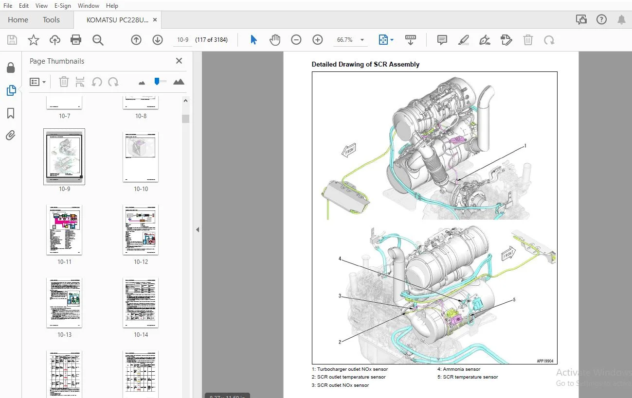
Urea SCR System 10-6
Layout Drawing of Urea SCR System 10-6
Urea SCR System Diagram 10-11
Function of Urea SCR System 10-12
Component Parts of Urea SCR System 10-21
Boot-up System 10-30
Layout Drawing of Boot-up System (Machine with KOMTRAX Terminal) 10-30
Layout Drawing of Boot-up System (Machine with Gateway Function Controller) 10-32
System Operating Lamp System 10-34
Battery Isolator 10-37
Engine System 10-38
Layout Drawing of Engine System 10-38
Engine Control System 10-40
Auto-Deceleration System 10-47
Engine Automatic Warm-up System 10-49
Overheat Prevention System 10-51
Turbocharger Protection System 10-54
Automatic Idle Stop System 10-56
Index 00 Index and Foreword
00-2 PC228US-11, PC228USLC-11
Component Parts of Engine System 10-60
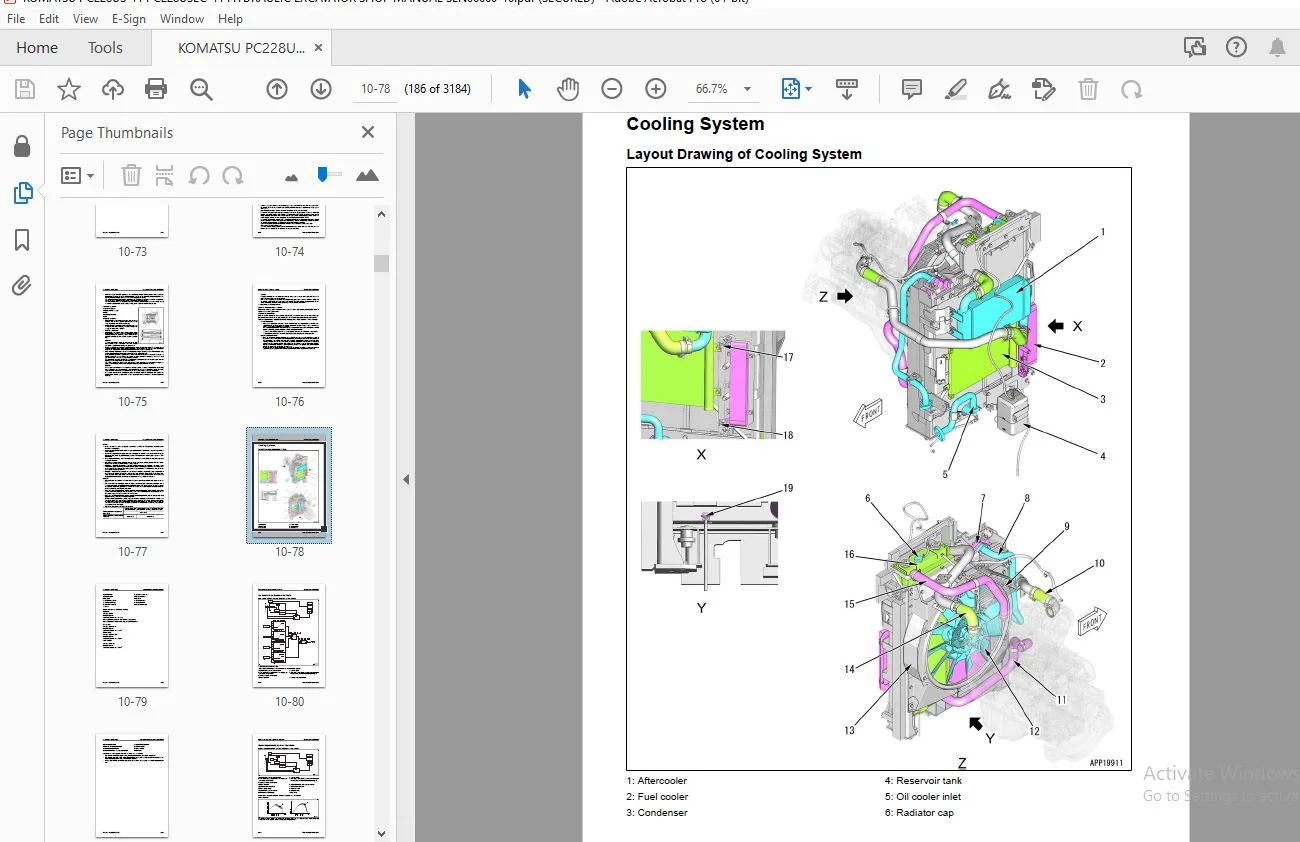
Cooling System 10-78
Layout Drawing of Cooling System 10-78
Fan Speed Control System of Fan Clutch 10-80
Engine Output Control System of Fan Clutch 10-82
Component Parts of Cooling System 10-84
Control System 10-85
Layout Drawing of Control System (Machine with KOMTRAX Terminal) 10-85
Layout Drawing of Control System (Machine with Gateway Function Controller) 10-88
Machine Monitor System 10-91
KomVision System 10-94
KOMTRAX System 10-98
Component Parts of Control System 10-100
Hydraulic System 10-139
Layout Drawing of Hydraulic System 10-139
CLSS 10-143
Engine and Pump Combined Control System 10-165
Pump and Valve Control System 10-171
Component Parts of Hydraulic System 10-174
Work Equipment System 10-262
Layout Drawing of Work Equipment System 10-262
One-Touch Power Maximizing System 10-267
PPC Lock System 10-269
Work Equipment and Travel Automatic Lock System 10-270
Attachment Oil Flow Adjuster System 10-272
Component Parts of Work Equipment System 10-274
Swing System 10-306
Layout Drawing of Swing System 10-306
Swing Control System Diagram 10-310
Component Parts of Swing System 10-314
Travel System 10-328
Layout Drawing of Travel System 10-328
System Diagram of Travel Control System 10-332
Component Parts of Travel System 10-334
Undercarriage and Frame 10-355
Layout Drawing of Undercarriage 10-355
Work Equipment 10-358
Structure of Work Equipment 10-358
Function of Work Equipment 10-359
Work Equipment Clearance Adjustment Shim 10-360
Bucket Clearance Adjustment Shim 10-361
CAB Related Parts 10-362
ROPS CAB 10-362
CAB Mount 10-364
CAB Tipping Stopper 10-365
Remove Wiring Harness Out of Cab 10-366
20 Standard Value Table 20-1
Table of Contents 20-2
Standard Value Table for Engine 20-3
Standard Value Table for Engine: PC228US-11 20-3
Standard Value Table for Engine: PC228USLC-11 20-8
Standard Value Table for Machine 20-13
Standard Value Table for Machine: PC228US-11 20-13
Standard Value Table for Machine: PC228USLC-11 20-27
Machine Posture and Procedures to Measure Performance 20-40
30 Testing and Adjusting 30-1
Table of Contents 30-2
Precautions Before Work 30-6
00 Index and Foreword Index
PC228US-11, PC228USLC-11 00-3
Related Information on Testing and Adjusting 30-7
Tools for Testing and Adjusting 30-7
Sketch of Tools for Testing and Adjusting 30-14
Engine and Cooling System 30-16
Examine Engine Speed 30-16
Examine Boost Pressure 30-19
Examine Exhaust Gas Color 30-22
Examine Mass Air Flow and Temperature Sensor 30-25
Examine and Adjust Valve Clearance 30-27
Examine Compression Pressure 30-30
Examine Blowby Pressure 30-35
Examine Engine Oil Pressure 30-37
Examine EGR Valve and VGT Oil Pressure 30-38
Examine Fuel Pressure 30-40
Examine Fuel Discharge, Return and Leakage 30-46
Bleed Air from Fuel System 30-53
Examine Fuel Circuit for Leakage 30-54
Handle Cylinder Cut-out Mode Operation 30-56
Handle No-Injection Cranking Operation 30-57
Examine and Adjust Air Conditioner Compressor Belt Tension 30-58
Examine Fan Belt and Alternator Belt 30-60
Examine Automatic Tensioner 30-61
Examine Cooling Fan Speed 30-62
Write Correction for Ash in Soot Accumulation to Engine Controller 30-63
Examine SCR Related Functions 30-64
Clean DEF Tank 30-90
Clean DEF Pump 30-94
Bleed Air from Coolant Circuit of DEF Tank 30-101
Power Train 30-103
Examine Swing Circle Bearing Clearance 30-103
Undercarriage and Frame 30-104
Examine and Adjust Track Tension 30-104
Hydraulic System 30-106
Release Remained Pressure in Hydraulic Circuit 30-106
Examine and Adjust Oil Pressure in Work Equipment, Swing, and Travel Circuits 30-112
Examine Oil Pressure of Control Circuit 30-123
Examine and adjust oil pressure in pump PC control circuit 30-125
Examine and Adjust Oil Pressure in Pump LS Control Circuit 30-129
Examine Outlet Pressure of Solenoid Valve 30-135
Examine PPC Valve Outlet Pressure 30-139
Adjust Play of Work Equipment and Swing PPC Valves 30-142
Examine Pump Swash Plate Sensor 30-143
Examine Parts Which Cause Hydraulic Drift of Work Equipment 30-144
Examine Oil Leakage 30-146
Bleed Air from Hydraulic System 30-149
Examine and Charge Accumulator (Made by NOK) Nitrogen Gas Pressure for Attachment (Low Pressure
Side) 30-153
Examine and Charge Accumulator Nitrogen Gas Pressure for Attachment (High Pressure Side) 30-157
Replace Accumulator Bladder on High Pressure Side for Attachment Piping 30-161
Work Equipment 30-168
Adjust Boom Angle Potentiometer 30-168
CAB Related Parts 30-169
Examine CAB Tipping Stopper 30-169
How to Adjust Mirrors 30-170
How to Examine and Adjust Slide Door 30-177
Electrical System 30-202
Set and Operate Machine Monitor 30-202
How to Start Up KOMTRAX Terminal (Machine with KOMTRAX Terminal) 30-286
Index 00 Index and Foreword
00-4 PC228US-11, PC228USLC-11
How to Start Up KOMTRAX System (Machine with Gateway Function Controller) 30-291
Adjust Rearview Camera Angle 30-296
Adjust KomVision Camera Angle 30-298
Adjust KomVision Related Function 30-301
Set Region of Bluetooth® Compatible Radio 30-321
Handle Voltage Circuit of Engine Controller 30-323
Handle Battery Isolator Switch (Machine with KOMTRAX Terminal) 30-324
Handle Battery Isolator Switch (Machine with Gateway Function Controller) 30-325
Examine Diodes 30-326
Pm Clinic 30-327
Pm Clinic Service 30-327
40 Troubleshooting 40-1
Table of Contents 40-2
Precautions Before Work 40-13
Related Information to Troubleshooting 40-14
General Troubleshooting Points 40-14
Troubleshooting Points for Urea SCR System 40-15
Sequence of Events in Troubleshooting 40-29
Checks Before Troubleshooting 40-31
Inspection Procedure Before Troubleshooting 40-33
Test in Accordance with Testing Procedure 40-35
Preparation for Troubleshooting of Electrical System 40-56
Procedure for Troubleshooting 40-63
Symptom and Troubleshooting Numbers 40-66
Information Shown in Troubleshooting Table 40-70
How to Diagnose Open Circuit of Hydraulic Pressure Sensor System Wiring Harness 40-72
Connector List and Layout (Machine with KOMTRAX Terminal) 40-75
Connector List and Layout (Machine with Gateway Function Controller) 40-89
Connector Contact Connection Table 40-103
T-Branch Box and T-Branch Adapter Table 40-143
Fuse Location Table (Machine with KOMTRAX Terminal) 40-149
Fuse Location Table (Machine with Gateway Function Controller) 40-152
Precautions When You Clean and Replace KDPF (KCSF and KDOC) 40-155
Prepare Short Circuit Electrical Connector (For Failure Codes [CA1883] and [CA3135]) 40-159
Failure Code Table 40-161
Troubleshooting by Failure Code (Display of Code) 40-180
Failure Code [6AZ0ZG] 40-180
Failure Code [879AKA] 40-182
Failure Code [879AKB] 40-183
Failure Code [879BKA] 40-184
Failure Code [879BKB] 40-186
Failure Code [879CKA] 40-188
Failure Code [879CKB] 40-189
Failure Code [879DKZ] 40-190
Failure Code [879EMC] 40-192
Failure Code [879FMC] 40-193
Failure Code [879GKX] 40-194
Failure Code [989L00] 40-196
Failure Code [989M00] 40-197
Failure Code [989N00] 40-198
Failure Code [A1U0N3] 40-199
Failure Code [A1U0N4] 40-201
Failure Code [A900FR] 40-203
Failure Code [A900N6] 40-204
Failure Code [A900NY] 40-205
Failure Code [AA10NX] 40-206
Failure Code [AB00KE] 40-208
Failure Code [AQ10N3] 40-210
00 Index and Foreword Index
PC228US-11, PC228USLC-11 00-5
Failure Code [AS00N3] 40-212
Failure Code [AS00R2] 40-214
Failure Code [AS00R3] 40-215
Failure Code [AS00R4] 40-216
Failure Code [AS00R5] 40-217
Failure Code [AS00R6] 40-218
Failure Code [AS00ZK] 40-219
Failure Code [AS10KM] 40-220
Failure Code [AS10NR] 40-221
Failure Code [AS10NT] 40-222
Failure Code [B@BAZG] 40-223
Failure Code [B@BAZK] 40-225
Failure Code [B@BCNS] 40-227
Failure Code [B@BCQA] 40-229
Failure Code [B@BCZK] 40-231
Failure Code [B@HANS] 40-233
Failure Code [CA115] 40-235
Failure Code [CA122] 40-240
Failure Code [CA123] 40-243
Failure Code [CA131] 40-245
Failure Code [CA132] 40-247
Failure Code [CA144] 40-249
Failure Code [CA145] 40-251
Failure Code [CA153] 40-253
Failure Code [CA154] 40-255
Failure Code [CA187] 40-257
Failure Code [CA221] 40-259
Failure Code [CA222] 40-261
Failure Code [CA227] 40-263
Failure Code [CA234] 40-264
Failure Code [CA238] 40-265
Failure Code [CA239] 40-266
Failure Code [CA249] 40-267
Failure Code [CA256] 40-269
Failure Code [CA271] 40-271
Failure Code [CA272] 40-273
Failure Code [CA322] 40-275
Failure Code [CA323] 40-277
Failure Code [CA324] 40-279
Failure Code [CA325] 40-281
Failure Code [CA331] 40-283
Failure Code [CA332] 40-285
Failure Code [CA343] 40-287
Failure Code [CA351] 40-289
Failure Code [CA352] 40-291
Failure Code [CA356] 40-293
Failure Code [CA357] 40-295
Failure Code [CA386] 40-297
Failure Code [CA428] 40-299
Failure Code [CA429] 40-301
Failure Code [CA435] 40-303
Failure Code [CA441] 40-305
Failure Code [CA442] 40-307
Failure Code [CA449] 40-308
Failure Code [CA451] 40-309
Failure Code [CA452] 40-311
Failure Code [CA488] 40-313
Failure Code [CA515] 40-316
Index 00 Index and Foreword
00-6 PC228US-11, PC228USLC-11
Failure Code [CA516] 40-318
Failure Code [CA553] 40-320
Failure Code [CA555] 40-321
Failure Code [CA556] 40-323
Failure Code [CA559] 40-325
Failure Code [CA595] 40-328
Failure Code [CA687] 40-330
Failure Code [CA689] 40-332
Failure Code [CA691] 40-335
Failure Code [CA692] 40-337
Failure Code [CA697] 40-339
Failure Code [CA698] 40-340
Failure Code [CA731] 40-341
Failure Code [CA778] 40-343
Failure Code [CA1117] 40-348
Failure Code [CA1664] 40-349
Failure Code [CA1669] 40-352
Failure Code [CA1673] 40-353
Failure Code [CA1677] 40-354
Failure Code [CA1678] 40-355
Failure Code [CA1682] 40-356
Failure Code [CA1683] 40-360
Failure Code [CA1684] 40-362
Failure Code [CA1686] 40-364
Failure Code [CA1691] 40-365
Failure Code [CA1694] 40-368
Failure Code [CA1695] 40-371
Failure Code [CA1696] 40-373
Failure Code [CA1712] 40-375
Failure Code [CA1713] 40-378
Failure Code [CA1714] 40-380
Failure Code [CA1715] 40-381
Failure Code [CA1776] 40-382
Failure Code [CA1777] 40-385
Failure Code [CA1843] 40-388
Failure Code [CA1844] 40-390
Failure Code [CA1879] 40-392
Failure Code [CA1881] 40-394
Failure Code [CA1883] 40-396
Failure Code [CA1885] 40-400
Failure Code [CA1887] 40-402
Failure Code [CA1921] 40-404
Failure Code [CA1922] 40-407
Failure Code [CA1942] 40-412
Failure Code [CA1993] 40-414
Failure Code [CA2185] 40-416
Failure Code [CA2186] 40-417
Failure Code [CA2249] 40-419
Failure Code [CA2271] 40-422
Failure Code [CA2272] 40-424
Failure Code [CA2288] 40-426
Failure Code [CA2311] 40-428
Failure Code [CA2349] 40-430
Failure Code [CA2353] 40-432
Failure Code [CA2357] 40-434
Failure Code [CA2381] 40-437
Failure Code [CA2382] 40-439
Failure Code [CA2383] 40-442
00 Index and Foreword Index
PC228US-11, PC228USLC-11 00-7
Failure Code [CA2386] 40-444
Failure Code [CA2387] 40-446
Failure Code [CA2555] 40-451
Failure Code [CA2556] 40-453
Failure Code [CA2637] 40-455
Failure Code [CA2639] 40-457
Failure Code [CA2771] 40-459
Failure Code [CA2777] 40-464
Failure Code [CA2976] 40-467
Failure Code [CA3133] 40-469
Failure Code [CA3134] 40-471
Failure Code [CA3135] 40-473
Failure Code [CA3142] 40-476
Failure Code [CA3143] 40-477
Failure Code [CA3144] 40-478
Failure Code [CA3146] 40-481
Failure Code [CA3147] 40-482
Failure Code [CA3148] 40-483
Failure Code [CA3151] 40-486
Failure Code [CA3165] 40-491
Failure Code [CA3229] 40-494
Failure Code [CA3231] 40-497
Failure Code [CA3232] 40-500
Failure Code [CA3235] 40-505
Failure Code [CA3239] 40-508
Failure Code [CA3241] 40-511
Failure Code [CA3242] 40-513
Failure Code [CA3251] 40-516
Failure Code [CA3253] 40-518
Failure Code [CA3254] 40-522
Failure Code [CA3255] 40-526
Failure Code [CA3256] 40-529
Failure Code [CA3311] 40-532
Failure Code [CA3312] 40-535
Failure Code [CA3313] 40-538
Failure Code [CA3314] 40-539
Failure Code [CA3315] 40-540
Failure Code [CA3316] 40-542
Failure Code [CA3317] 40-543
Failure Code [CA3318] 40-544
Failure Code [CA3319] 40-547
Failure Code [CA3321] 40-549
Failure Code [CA3322] 40-551
Failure Code [CA3419] 40-553
Failure Code [CA3421] 40-555
Failure Code [CA3497] 40-557
Failure Code [CA3498] 40-558
Failure Code [CA3543] 40-559
Failure Code [CA3545] 40-564
Failure Code [CA3547] 40-566
Failure Code [CA3558] 40-567
Failure Code [CA3559] 40-569
Failure Code [CA3562] 40-571
Failure Code [CA3563] 40-573
Failure Code [CA3567] 40-576
Failure Code [CA3568] 40-579
Failure Code [CA3571] 40-584
Failure Code [CA3572] 40-586
Index 00 Index and Foreword
00-8 PC228US-11, PC228USLC-11
Failure Code [CA3574] 40-588
Failure Code [CA3575] 40-591
Failure Code [CA3577] 40-593
Failure Code [CA3578] 40-595
Failure Code [CA3582] 40-597
Failure Code [CA3583] 40-605
Failure Code [CA3596] 40-607
Failure Code [CA3649] 40-612
Failure Code [CA3681] 40-615
Failure Code [CA3682] 40-619
Failure Code [CA3713] 40-624
Failure Code [CA3717] 40-627
Failure Code [CA3718] 40-628
Failure Code [CA3725] 40-629
Failure Code [CA3741] 40-632
Failure Code [CA3748] 40-633
Failure Code [CA3751] 40-635
Failure Code [CA3755] 40-637
Failure Code [CA3866] 40-639
Failure Code [CA3867] 40-643
Failure Code [CA3868] 40-646
Failure Code [CA3899] 40-651
Failure Code [CA3911] 40-653
Failure Code [CA3912] 40-658
Failure Code [CA3932] 40-660
Failure Code [CA3933] 40-662
Failure Code [CA3934] 40-664
Failure Code [CA3935] 40-667
Failure Code [CA3936] 40-669
Failure Code [CA4151] 40-671
Failure Code [CA4152] 40-677
Failure Code [CA4155] 40-682
Failure Code [CA4156] 40-684
Failure Code [CA4157] 40-687
Failure Code [CA4158] 40-689
Failure Code [CA4159] 40-690
Failure Code [CA4161] 40-691
Failure Code [CA4162] 40-694
Failure Code [CA4163] 40-697
Failure Code [CA4164] 40-698
Failure Code [CA4165] 40-700
Failure Code [CA4166] 40-702
Failure Code [CA4168] 40-704
Failure Code [CA4169] 40-708
Failure Code [CA4171] 40-712
Failure Code [CA4249] 40-716
Failure Code [CA4251] 40-720
Failure Code [CA4259] 40-724
Failure Code [CA4261] 40-727
Failure Code [CA4277] 40-730
Failure Code [CA4281] 40-733
Failure Code [CA4459] 40-736
Failure Code [CA4461] 40-738
Failure Code [CA4658] 40-741
Failure Code [CA4731] 40-744
Failure Code [CA4732] 40-745
Failure Code [CA4739] 40-746
Failure Code [CA4768] 40-747
00 Index and Foreword Index
PC228US-11, PC228USLC-11 00-9
Failure Code [CA4769] 40-749
Failure Code [CA4842] 40-752
Failure Code [CA4952] (Machine with KOMTRAX Terminal) 40-755
Failure Code [CA4952] (Machine with Gateway Function Controller) 40-757
Failure Code [CA5115] 40-759
Failure Code [CA5179] 40-762
Failure Code [CA5181] 40-764
Failure Code [CA5383] 40-766
Failure Code [D110KB] 40-768
Failure Code [D19JKZ] 40-770
Failure Code [D811MC] (Machine with KOMTRAX Terminal) 40-773
Failure Code [D811MC] (Machine with Gateway Function Controller) 40-774
Failure Code [D862KA] (Machine with KOMTRAX Terminal) 40-775
Failure Code [D862KA] (Machine with Gateway Function Controller) 40-777
Failure Code [D8ALKA] (Machine with KOMTRAX Terminal) 40-779
Failure Code [D8ALKA] (Machine with Gateway Function Controller) 40-782
Failure Code [D8ALKB] (Machine with KOMTRAX Terminal) 40-785
Failure Code [D8ALKB] (Machine with Gateway Function Controller) 40-787
Failure Code [D8AQKR] (Machine with KOMTRAX Terminal) 40-789
Failure Code [D8AQKR] (Machine with Gateway Function Controller) 40-796
Failure Code [D8ARKR] 40-803
Failure Code [D8G1KT] 40-808
Failure Code [D8G6KT] 40-809
Failure Code [DA20MC] 40-810
Failure Code [DA22KK] 40-811
Failure Code [DA25KP] 40-814
Failure Code [DA29KQ] 40-818
Failure Code [DA2LKA] (Machine with KOMTRAX Terminal) 40-821
Failure Code [DA2LKA] (Machine with Gateway Function Controller) 40-824
Failure Code [DA2LKB] (Machine with KOMTRAX Terminal) 40-827
Failure Code [DA2LKB] (Machine with Gateway Function Controller) 40-829
Failure Code [DA2QKR] (Machine with KOMTRAX Terminal) 40-831
Failure Code [DA2QKR] (Machine with Gateway Function Controller) 40-840
Failure Code [DA2RKR] (Machine with KOMTRAX Terminal) 40-849
Failure Code [DA2RKR] (Machine with Gateway Function Controller) 40-854
Failure Code [DAF0KM] 40-859
Failure Code [DAF0MB] 40-860
Failure Code [DAF0MC] 40-861
Failure Code [DAF8KB] 40-862
Failure Code [DAF9KQ] 40-864
Failure Code [DAFGMC] (Machine with KOMTRAX Terminal) 40-865
Failure Code [DAFGMC] (Machine with Gateway Function Controller) 40-866
Failure Code [DAFLKA] (Machine with KOMTRAX Terminal) 40-867
Failure Code [DAFLKA] (Machine with Gateway Function Controller) 40-870
Failure Code [DAFLKB] (Machine with KOMTRAX Terminal) 40-873
Failure Code [DAFLKB] (Machine with Gateway Function Controller) 40-875
Failure Code [DAFQKR] (Machine with KOMTRAX Terminal) 40-877
Failure Code [DAFQKR] (Machine with Gateway Function Controller) 40-885
Failure Code [DAZ9KQ] 40-893
Failure Code [DAZQKR] (Machine with KOMTRAX Terminal) 40-894
Failure Code [DAZQKR] (Machine with Gateway Function Controller) 40-901
Failure Code [DB2QKR] (Machine with KOMTRAX Terminal) 40-908
Failure Code [DB2QKR] (Machine with Gateway Function Controller) 40-916
Failure Code [DB2RKR] (Machine with KOMTRAX Terminal) 40-924
Failure Code [DB2RKR] (Machine with Gateway Function Controller) 40-929
Failure Code [DBP0KM] 40-934
Failure Code [DBP0KT] 40-935
Failure Code [DBP5KB] 40-936
Index 00 Index and Foreword
00-10 PC228US-11, PC228USLC-11
Failure Code [DBP5KY] 40-938
Failure Code [DBPQKR] (Machine with KOMTRAX Terminal) 40-940
Failure Code [DBPQKR] (Machine with Gateway Function Controller) 40-948
Failure Code [DDNRKA] 40-956
Failure Code [DDNRKY] 40-958
Failure Code [DDNS00] 40-960
Failure Code [DFB1KZ] 40-962
Failure Code [DFB2KZ] 40-964
Failure Code [DFB3L8] 40-966
Failure Code [DFB4L8] 40-968
Failure Code [DFB5KZ] 40-970
Failure Code [DFB6KZ] 40-972
Failure Code [DGH2KA] 40-974
Failure Code [DGH2KB] 40-976
Failure Code [DHA4KA] 40-978
Failure Code [DHAAMA] 40-980
Failure Code [DHACMA] 40-982
Failure Code [DHPAMA] 40-984
Failure Code [DHPBMA] 40-986
Failure Code [DHS3MA] 40-988
Failure Code [DHS4MA] 40-990
Failure Code [DHS8MA] 40-992
Failure Code [DHS9MA] 40-994
Failure Code [DHSAMA] 40-996
Failure Code [DHSBMA] 40-998
Failure Code [DHSCMA] 40-1000
Failure Code [DHSDMA] 40-1002
Failure Code [DHSFMA] 40-1004
Failure Code [DHSGMA] 40-1006
Failure Code [DHSHMA] 40-1008
Failure Code [DHSJMA] 40-1010
Failure Code [DHX1MA] 40-1012
Failure Code [DKR0MA] 40-1014
Failure Code [DKR1MA] 40-1017
Failure Code [DKULKA] 40-1020
Failure Code [DKULKB] 40-1022
Failure Code [DKULKY] 40-1024
Failure Code [DLM5KA] 40-1026
Failure Code [DLM5MB] 40-1028
Failure Code [DR10KA] 40-1031
Failure Code [DR12KA] 40-1033
Failure Code [DR20KA] 40-1035
Failure Code [DR21KX] 40-1037
Failure Code [DR31KX] 40-1039
Failure Code [DR40KA] 40-1041
Failure Code [DUMBKA] (Machine with KOMTRAX Terminal) 40-1043
Failure Code [DUMBKA] (Machine with Gateway Function Controller) 40-1046
Failure Code [DUMBKB] (Machine with KOMTRAX Terminal) 40-1049
Failure Code [DUMBKB] (Machine with Gateway Function Controller) 40-1051
Failure Code [DV00KB] 40-1053
Failure Code [DV20KB] 40-1054
Failure Code [DW43KA] 40-1056
Failure Code [DW43KB] 40-1058
Failure Code [DW43KY] 40-1060
Failure Code [DW45KA] 40-1062
Failure Code [DW45KB] 40-1065
Failure Code [DW45KY] 40-1068
Failure Code [DW4CKY] 40-1070
00 Index and Foreword Index
PC228US-11, PC228USLC-11 00-11
Failure Code [DW4GKA] 40-1072
Failure Code [DW4GKB] 40-1074
Failure Code [DW91KA] 40-1076
Failure Code [DW91KB] 40-1078
Failure Code [DW91KY] 40-1080
Failure Code [DWA2KA] 40-1082
Failure Code [DWA2KB] 40-1084
Failure Code [DWA2KY] 40-1086
Failure Code [DWK0KA] 40-1088
Failure Code [DWK0KB] 40-1090
Failure Code [DWK0KY] 40-1092
Failure Code [DWK2KA] 40-1094
Failure Code [DWK2KB] 40-1096
Failure Code [DWK2KY] 40-1098
Failure Code [DWK8KA] 40-1100
Failure Code [DWK8KB] 40-1102
Failure Code [DWK8KY] 40-1104
Failure Code [DWN5KA] 40-1106
Failure Code [DWN5KB] 40-1109
Failure Code [DWN5KY] 40-1111
Failure Code [DXA8KA] 40-1113
Failure Code [DXA8KB] 40-1115
Failure Code [DXA9KA] 40-1117
Failure Code [DXA9KB] 40-1119
Failure Code [DXE0KA] 40-1121
Failure Code [DXE0KB] 40-1123
Failure Code [DXE4KA] 40-1125
Failure Code [DXE4KB] 40-1127
Failure Code [DXE4KY] 40-1129
Failure Code [DXE5KA] 40-1131
Failure Code [DXE5KB] 40-1133
Failure Code [DXE6KA] 40-1135
Failure Code [DXE6KB] 40-1137
Failure Code [DXE7KA] 40-1139
Failure Code [DXE7KB] 40-1141
Failure Code [DXE7KY] 40-1143
Failure Code [DXE8KA] 40-1145
Failure Code [DXE8KB] 40-1147
Failure Code [DXE8KY] 40-1149
Failure Code [DXE9KA] 40-1151
Failure Code [DXE9KB] 40-1153
Failure Code [DXE9KY] 40-1155
Failure Code [DXEAKA] 40-1157
Failure Code [DXEAKB] 40-1159
Failure Code [DXEAKY] 40-1161
Failure Code [DY20KA] 40-1163
Failure Code [DY20MA] 40-1165
Failure Code [DY2CKB] 40-1167
Failure Code [DY2DKB] 40-1169
Failure Code [DY2EKB] 40-1171
Failure Code [F311KA] 40-1173
Failure Code [F311KB] 40-1175
Failure Code [F312KA] 40-1177
Failure Code [F312KB] 40-1179
Failure Code [F313KA] 40-1181
Failure Code [F313KB] 40-1183
Failure Code [F314KA] 40-1186
Failure Code [F314KB] 40-1188
Index 00 Index and Foreword
00-12 PC228US-11, PC228USLC-11
Failure Code [F315KB] 40-1190
Failure Code [F315KY] 40-1192
Failure Code [F316KB] 40-1194
Failure Code [F316KY] 40-1196
Failure Code [F318KB] 40-1198
Failure Code [F318KY] 40-1201
Failure Code [F31AKB] 40-1203
Failure Code [F31AKY] 40-1205
Failure Code [F31BKB] 40-1207
Failure Code [F31BKY] 40-1209
Failure Code [F31CKB] 40-1211
Failure Code [F31CKY] 40-1213
Failure Code [F31DKB] 40-1215
Failure Code [F31DKY] 40-1217
Failure Code [F31EKB] 40-1219
Failure Code [F31EKY] 40-1221
Troubleshooting of Electrical System (E-Mode) 40-1223
E-1 Engine Does Not Start (Engine Does Not Crank) 40-1223
E-2 Manual Preheating System Does Not Operate 40-1229
E-3 Automatic Preheating System Does Not Operate 40-1232
E-4 While Preheating is in Operation, Preheating Monitor Does Not Come On 40-1234
E-5 When Starting Switch is Turned to ON Position, Machine Monitor Shows Nothing 40-1236
E-6 While Starting Switch is Turned to ON Position (with Engine Stopped), Engine Oil Level Monitor
Comes On in Yellow 40-1239
E-7 While Starting Switch is Turned to ON Position (with Engine Stopped), Radiator Coolant Level
Monitor Comes On in Yellow 40-1240
E-8 Engine Coolant Temperature Monitor Comes On While Engine is in Operation 40-1241
E-9 Hydraulic Oil Temperature Monitor Comes On in White While Engine Runs 40-1242
E-10 Air Cleaner Clogging Monitor Comes On in Yellow While Engine Runs 40-1243
E-11 Charge Level Monitor Comes On in Red While Engine is in Operation 40-1244
E-12 Fuel Level Monitor Comes On in Red While Engine Runs 40-1245
E-13 Water Separator Monitor Comes On in Red While Engine Runs 40-1246
E-14 Engine Coolant Temperature Monitor Comes On in Red While Engine is in Operation 40-1247
E-15 Engine Oil Pressure Monitor Comes on in Red While Engine is in Operation 40-1248
E-16 Hydraulic Oil Temperature Monitor Comes On in Red While Engine is in Operation 40-1249
E-17 Fuel Gauge Display Does Not Move from Minimum or Maximum 40-1250
E-18 Display of Fuel Gauge is Different from Actual Fuel Level 40-1252
E-19 Coolant Temperature Gauge Display Does Not Move from Minimum or Maximum 40-1253
E-20 Display of Coolant Temperature Gauge is Different from Actual Coolant Temperature 40-1254
E-21 Hydraulic Oil Temperature Gauge Display Does Not Move from Minimum or Maximum 40-1255
E-22 Display of Hydraulic Oil Temperature Gauge is Different from Actual Oil Temperature 40-1257
E-23 Some Areas of Machine Monitor Screen are Not Shown 40-1258
E-24 Function Switch Does Not Operate 40-1259
E-25 Automatic Warm-up System Does Not Work (in Cold Weather) 40-1260
E-26 When Auto-Decelerator Switch is Operated, Auto-Decelerator Monitor Does Not Come On or
Does Not Go Out 40-1261
E-27 Auto-Decelerator is Not Operated or Canceled with Lever 40-1262
E-28 When Working Mode Switch is Operated, Working Mode Selection Screen is Not Shown 40-1263
E-29 When Working Mode is Changed, Setting of Engine and Hydraulic Pump is Not Changed 40-1264
E-30 When Travel Speed Switch is Operated, Travel Speed Monitor Does Not Change 40-1265
E-31 When Travel Speed Selection is Changed, Actual Travel Speed Does Not Change 40-1266
E-32 Alarm Buzzer Cannot be Canceled 40-1268
E-33 Service Meter is Not Shown, While Starting Switch is in OFF Position 40-1269
E-34 Service Mode Cannot be Selected 40-1270
E-35 All of Work Equipment, Swing, and Travel Mechanism Do Not Move 40-1271
E-36 All Work Equipment, Swing and Travel Do Not Lock 40-1274
E-37 When Swing Brake Cancel Switch is Set to Cancel Position, Machine Cannot Swing 40-1276
00 Index and Foreword Index
PC228US-11, PC228USLC-11 00-13
E-38 When Swing Brake Cancel Switch is Set to Normal Position, Swing Holding Brake Does Not Operate
40-1279
E-39 One-Touch Power Maximizing Function Does Not Operate Correctly or Monitor Does Not Show
40-1281
E-40 One-Touch Power Maximizing Function is Not Cancelled 40-1283
E-41 Alarm Does Not Sound During Travel 40-1284
E-42 Alarm Does Not Stop When Machine Stops 40-1286
E-43 Horn Does Not Sound 40-1287
E-44 Horn Does Not Stop 40-1290
E-45 When Wiper Switch is Operated, Wiper Monitor Does Not Come On or Go Out 40-1292
E-46 When Wiper Switch is Operated, Windshield Wiper Does Not Operate 40-1293
E-47 Window Washer Does Not Operate When Window Washer Switch is Operated 40-1295
E-48 “Boom RAISE” is Not Shown Correctly with Monitoring Function 40-1296
E-49 “Boom LOWER” is Not Shown Correctly with Monitoring Function 40-1297
E-50 “Arm OUT” is Not Shown Correctly with Monitoring Function 40-1298
E-51 “Arm IN” is Not Shown Correctly with Monitoring Function 40-1299
E-52 “Bucket DUMP” is Not Shown Correctly with Monitoring Function 40-1300
E-53 “Bucket CURL” is Not Shown Correctly with Monitoring Function 40-1301
E-54 “Swing” is Not Shown Correctly with Monitoring Function 40-1302
E-55 “Travel” is Not Shown Correctly with Monitoring Function 40-1303
E-56 Service is Not Shown Correctly with Monitoring Function 40-1304
E-57 Attachment Hydraulic Circuit Cannot be Changed 40-1306
E-58 KOMTRAX System Does Not Operate Correctly 40-1308
Troubleshooting for Hydraulic and Mechanical Systems (H Mode) 40-1309
Information Shown in Troubleshooting Table (H-Mode) 40-1309
System Chart of Hydraulic and Mechanical Systems 40-1310
Failure Mode and Cause Table 40-1312
H-1 All Work Equipment, Swing and Travel Do Not Work 40-1321
H-2 All Work Equipment, Swing and Travel Lack Speed and Power 40-1322
H-3 Fine Control Performance or Response is Unsatisfactory 40-1325
H-4 Unusual Noise is Heard from Around Hydraulic Pump 40-1326
H-5 Engine Speed Drops Largely or Engine Stops 40-1327
H-6 Speed or Power of Boom is Low 40-1329
H-7 Arm Speed or Power is Low 40-1334
H-8 Bucket Speed or Power is Low 40-1339
H-9 Work Equipment Does Not Move in Single Operation 40-1342
H-10 Hydraulic Drift of Boom is Large 40-1343
H-11 Hydraulic Drift of Arm is Large 40-1345
H-12 Hydraulic Drift of Bucket is Large 40-1347
H-13 When Single Work Equipment is Released Hydraulically, Other Work Equipment Moves 40-1348
H-14 Time Lag of Work Equipment is Large 40-1349
H-15 One-Touch Power Maximizing Function Does Not Operate 40-1350
H-16 Attachment Circuit Cannot be Changed 40-1351
H-17 Oil Flow in Attachment Circuit Cannot be Changed 40-1352
H-18 In Mixed Operation of Work Equipment, Work Equipment with Heavier Load Moves Slower40-1353
H-19 In Mixed Operation of Swing and Travel, Travel Speed Decreases Largely 40-1354
H-20 In Mixed Operation of Swing and Boom RAISE, Boom RAISE Speed is Low 40-1355
H-21 Machine Does Not Travel Straight 40-1356
H-22 Machine is Not Steered Correctly or Steering Power is Low 40-1358
H-23 Travel Speed is Low 40-1361
H-24 One of Tracks Does Not Run 40-1363
H-25 Travel Speed Does Not Change, or Travel Speed is Too Slow or Fast 40-1364
H-26 Upper Structure Does Not Swing to Right and Left 40-1365
H-27 Upper Structure Swings Only to Right or Left 40-1366
H-28 Swing Acceleration or Swing Speed is Low in Right and Left Directions 40-1367
H-29 Swing Acceleration or Swing Speed is Low in Only One Direction 40-1368
H-30 Upper Structure Overruns Too Much When It Stops Swing Operation (Right and Left) 40-1369
H-31 Upper Structure Overruns Too Much When It Stops Swing Operation (Only One Direction)40-1370
Index 00 Index and Foreword
00-14 PC228US-11, PC228USLC-11
H-32 Shock is Large When Upper Structure Stops Swing Operation 40-1371
H-33 There is Large Unusual Noise When It Stops Swing Operation 40-1372
H-34 Swing Drift on a Slope is Large (While Swing Parking Brake is Applied) 40-1373
H-35 Swing Drift on a Slope is Large (While Swing Parking Brake is Released) 40-1374
H-36 Fan Speed is Abnormal (Too High or Low, or Does Not Rotate) 40-1375
H-37 Unusual Noise is Heard from Around Fan 40-1376
Troubleshooting of Engine (S-Mode) 40-1377
Information Shown in Troubleshooting Table (S-Mode) 40-1377
S-1 Engine Does Not Crank When Starting Switch is Turned to Start Position 40-1378
S-2 Engine Cranks but No Exhaust Smoke Comes Out 40-1379
S-3 Fuel is Injected but Engine Does Not Start (Misfiring: Engine Cranks but Does Not Start) 40-1380
S-4 Engine Startability is Unsatisfactory 40-1382
S-5 Engine Does Not Pick Up Smoothly 40-1384
S-6 Engine Stops During Operation 40-1386
S-7 Engine Runs Rough or is Not Stable 40-1388
S-8 Engine Lacks Power 40-1389
S-9 KDPF Becomes Clogged in a Short Time 40-1391
S-10 Engine Oil Consumption is Excessive 40-1393
S-11 Oil Becomes Dirty Quickly 40-1394
S-12 Fuel Consumption is Excessive 40-1395
S-13 Oil is in Coolant (or Coolant Spurts Back or Coolant 40-1396
S-14 Oil Pressure Drops 40-1397
S-15 Fuel Mixes Into Engine Oil 40-1399
S-16 Water Mixes Into Engine Oil (Milky) 40-1400
S-17 Coolant Temperature Increases Too High (Overheating) 40-1401
S-18 Unusual Noise is Heard 40-1402
S-19 Vibration is Excessive 40-1403
S-20 Air Cannot be Bled from Fuel Circuit 40-1404
S-21 Active Regeneration is Done Frequently 40-1405
S-22 Active Regeneration Continues Long 40-1407
S-23 White Smoke is Exhausted During Active Regeneration 40-1408
S-24 DEF Consumption is Excessive 40-1409
S-25 There is Unusual Smell (Irritating Odor) 40-1411
S-26 Foreign Materials Enter DEF (DEF Increases) 40-1412
50 Disassembly and Assembly 50-1
Table of Contents 50-2
Precautions Before Work 50-7
Related Information on Disassembly and Assembly 50-8
How to Read This Manual 50-8
Coating Materials List 50-9
Special Tool List 50-14
Sketches of Special Tools 50-33
Engine and Cooling System 50-39
Remove and Install Supply Pump Assembly 50-39
Remove and Install Injector Assembly 50-45
Remove and Install Cylinder Head Assembly 50-61
Remove and Install EGR Valve Assembly 50-89
Remove and Install EGR Cooler Assembly 50-92
Remove and Install Starter Assembly 50-99
Remove and Install Alternator Belt 50-104
Remove and Install Radiator Assembly 50-111
Remove and Install Hydraulic Oil Cooler Assembly 50-118
Remove and Install Aftercooler Assembly 50-132
Remove and Install Fan Clutch Assembly 50-136
Remove and Install Engine Assembly 50-147
Remove and Install Engine Front Oil Seal 50-169
Remove and Install Engine Rear Oil Seal 50-180
Remove and Install Fuel Cooler Assembly 50-184
00 Index and Foreword Index
PC228US-11, PC228USLC-11 00-15
Remove and Install Engine Hood Assembly 50-188
Remove and Install Fuel Tank Assembly 50-191
Remove and Install DEF Tank Assembly 50-204
Remove and Install DEF Tank Sensor Flange Assembly 50-218
Remove and Install DEF Tank Sensor 50-230
Remove and Install DEF Tank Strainer 50-234
Remove and Install DEF Tank Filler Port Filter 50-235
Remove and Install KDPF Assembly 50-239
Disassemble and Assemble KDPF Assembly 50-247
Remove and Install SCR Assembly 50-256
Remove and Install KDPF and SCR Assembly 50-260
Remove and Install KDPF and SCR Assembly Bracket 50-280
Remove and Install Bellows Pipe Assembly 50-283
Remove and Install KCCV Assembly 50-287
Remove and Install DEF Mixing Tube 50-289
Remove and Install DEF Injector 50-300
Remove and Install DEF Pump 50-309
Remove and Install DEF Hose 50-317
Remove and Install Air Cleaner Assembly 50-338
Remove and Install Air Conditioner Compressor Assembly 50-344
Remove and Install Air Conditioner Condenser Assembly 50-350
Power Train 50-352
Remove and Install Travel Motor and Final Drive Assembly 50-352
Disassemble and Assemble Final Drive Assembly 50-354
Remove and Install Swing Motor and Swing Machinery Assembly 50-366
Disassemble and Assemble Swing Machinery Assembly 50-370
Remove and Install Swing Circle Assembly 50-381
Undercarriage and Frame 50-383
Separate and Connect Track Assembly 50-383
Remove and Install Sprocket 50-387
Remove and Install Idler and Idler Cushion Assembly 50-389
Disassemble and Assemble Idler Assembly 50-391
Disassemble and Assemble Idler Cushion Assembly 50-396
Disassemble and Assemble Track Roller Assembly 50-399
Disassemble and Assemble Carrier Roller Assembly 50-403
Remove and Install Revolving Frame Assembly 50-407
Remove and Install Counterweight Assembly 50-412
Remove and Install Counterweight Assembly for Maintenance 50-422
Hydraulic System 50-431
Remove and Install Center Swivel Joint Assembly 50-431
Disassemble and Assemble Center Swivel Joint Assembly 50-435
Remove and Install Hydraulic Tank Assembly 50-438
Remove and Install Main Pump Assembly 50-456
Remove and Install Control Valve Assembly 50-467
Disassemble and Assemble Control Valve Assembly 50-495
Disassemble and Assemble Work Equipment PPC Valve Assembly 50-501
Disassemble and Assemble Travel PPC Valve Assembly 50-504
Work Equipment 50-507
Remove and Install Work Equipment Assembly 50-507
Disassemble and Assemble Work Equipment Cylinder Assembly 50-513
CAB Related Parts 50-522
Remove and Install Operator Cab Assembly 50-522
Remove and Install Slide Door 50-535
Remove and Install Operator Cab Glass (Adhered Glass) 50-537
Remove and Install Front Window Assembly 50-548
Remove and Install Floor Frame Assembly 50-556
Remove and Install Air Conditioner Unit Assembly 50-568
Remove and Install Operator Seat 50-580
Index 00 Index and Foreword
00-16 PC228US-11, PC228USLC-11
How to Remove and Install Seat Belt 50-582
Remove and Install Work Equipment Control Lever Assembly 50-584
Remove and Install Front Wiper Assembly 50-598
Electrical System 50-612
Remove and Install Engine Controller Assembly 50-612
Remove and Install Pump Controller Assembly 50-616
Remove and Install KomVision Controller Assembly 50-621
Remove and Install Machine Monitor Assembly 50-625
Remove and Install Mass Air Flow and Temperature Sensor 50-632
Remove and Install KCCV Crankcase Pressure Sensor 50-635
Remove and Install SCR Temperature Sensor 50-639
Remove and Install KomVision Camera 50-645
Remove and Install KOMTRAX Terminal Assembly 50-650
Remove and Install Gateway Function Controller Assembly 50-654
Remove and Install Communication Terminal 50-658
Remove and Install Communication Terminal Wiring Harness 50-661
60 Maintenance Standard 60-1
Table of Contents 60-2
Engine and Cooling System 60-3
Maintenance Standard for Engine Mount 60-3
Maintenance Standard for Cooling System 60-4
Power Train 60-6
Maintenance Standard for Swing Circle 60-6
Maintenance Standard for Swing Machinery 60-7
Maintenance Standard for Final Drive 60-9
Maintenance Standard for Sprocket 60-11
Maintenance Standard for Sprocket Tooth Profile Full-Scale Drawing 60-12
Undercarriage and Frame 60-13
Maintenance Standard for Track Frame and Idler Cushion 60-13
Maintenance Standard for Idler 60-15
Maintenance Standard for Track Roller 60-17
Maintenance Standard for Carrier Roller 60-19
Maintenance Standard for Track Shoes 60-20
Maintenance Standard for Triple Shoes 60-23
Maintenance Standard for Road Liner 60-24
Maintenance Standard for Flat Shoes 60-25
Hydraulic System 60-26
Maintenance Standard for Hydraulic Tank 60-26
Maintenance Standard for Main Pump 60-27
Maintenance Standard for LS-EPC Valve 60-28
Maintenance Standard for PC-EPC Valve 60-29
Maintenance Standard for Swing Motor 60-30
Maintenance Standard for Travel Motor 60-33
Maintenance Standard for Control Valve 60-36
Maintenance Standard for Boom Anti-Drop Valve 60-46
Maintenance Standard for Arm Anti-Drop Valve 60-48
Maintenance Standard for Work Equipment and Swing PPC Valve 60-50
Maintenance Standard for Travel PPC Valve 60-53
Maintenance Standard for 1st-Line Attachment PPC Valve (with EPC Valve) 60-56
Maintenance Standard for 2nd-Line Attachment PPC Valve 60-59
Maintenance Standard for Solenoid Valve 60-61
Maintenance Standard for Attachment Circuit Selector Valve (For High Pressure) 60-62
Maintenance Standard for Attachment Circuit Selector Valve (For Low Pressure) 60-63
Maintenance Standard for Center Swivel Joint 60-64
Work Equipment 60-65
Maintenance Standard for Work Equipment Linkage 60-65
Maintenance Standard for Boom Cylinder (Large Diameter Piston) 60-74
Maintenance Standard for Arm Cylinder 60-75
00 Index and Foreword Index
PC228US-11, PC228USLC-11 00-17
Maintenance Standard for Bucket Cylinder 60-76
80 Appendix 80-1
Table of Contents 80-2
Precautions Before Work 80-4
Air Conditioner System 80-5
Precautions for Refrigerant 80-5
Air Conditioner Component 80-6
Specifications of Air Conditioner 80-8
Structure and Function of Refrigeration Cycle 80-9
Outline of Refrigeration Cycle 80-10
Component Parts of Air Conditioner System 80-12
Air Conditioner Unit 80-12
Component Parts of Air Conditioner Unit 80-15
Air Conditioner Controller 80-18
Compressor 80-19
Condenser 80-20
Air Conditioner Related Sensors 80-22
Explanation of Procedure for Test of and Troubleshooting of Air Conditioner 80-24
Circuit Diagram and Configuration of Connector Pins of Air Conditioner 80-26
System Diagram of Air Conditioner 80-28
Input and Output Signals of Air Conditioner Controller 80-29
Locations of Air Conditioner Parts and Layout of Connectors 80-31
Examine Air Leakage (Duct) 80-40
How to Examine Air Leakage (Duct) 80-40
Examine Air Conditioner with Self-Diagnosis Function 80-42
Open the Electrical System Abnormality Record Screen in Service Mode of Machine Monitor 80-43
Examine Vent (Mode) Changeover 80-44
How to Examine Vent (Mode) Changeover 80-44
Examine Fresh/Recirc Air Changeover 80-45
How to Examine Fresh/Recirc Air Changeover 80-45
Examine Sunlight Sensor 80-46
How to Examine Sunlight Sensor 80-46
Examine Refrigerant (Dual) Pressure Switch 80-47
How to Examine Refrigerant (Dual) Pressure Switch 80-47
Examine Relay 80-49
How to Examine Relay 80-49
Air Conditioner Troubleshooting Chart 1 80-50
Air Conditioner Troubleshooting Chart 2 80-51
Information Shown in Troubleshooting Table 80-54
Failure Code [879AKA] 80-55
Failure Code [879AKB] 80-56
Failure Code [879BKA] 80-57
Failure Code [879BKB] 80-59
Failure Code [879CKA] 80-61
Failure Code [879CKB] 80-62
Failure Code [879DKZ] 80-63
Failure Code [879EMC] 80-65
Failure Code [879FMC] 80-66
Failure Code [879GKX] 80-67
A-1 Troubleshooting for Power Supply System (Air Conditioner Does Not Operate) 80-69
A-2 Troubleshooting for Compressor and Refrigerant System (Air is Not Cooled) 80-71
A-3 Troubleshooting for Blower Motor System (No Air Comes Out or Air Flow is Abnormal) 80-74
A-4 Troubleshooting for Fresh/Recirc Air Changeover 80-76
Troubleshooting by Gauge Pressure 80-78
Connect Service Tool 80-80
How to Connect Service Tool 80-80
Precautions for Disconnection and Connection of Air Conditioner Piping 80-82
Handle Compressor Oil 80-84
Index 00 Index and Foreword
00-18 PC228US-11, PC228USLC-11
How to Replace Desiccant 80-86
90 Circuit Diagrams 90-1
Table of Contents 90-2
Hydraulic Circuit Diagram 90-3
Symbols Used in Hydraulic Circuit Diagram 90-3
Hydraulic Circuit Diagram (1/5) 90-7
Hydraulic Circuit Diagram (2/5) 90-9
Hydraulic Circuit Diagram (3/5) 90-11
Hydraulic Circuit Diagram (4/5) 90-13
Hydraulic Circuit Diagram (5/5) 90-15
Electrical Circuit Diagram 90-17
Symbols Used in Electric Circuit Diagram 90-17
Electrical Circuit Diagram (Machine with KOMTRAX Terminal) (1/8) 90-21
Electrical Circuit Diagram (Machine with KOMTRAX Terminal) (2/8) 90-23
Electrical Circuit Diagram (Machine with KOMTRAX Terminal) (3/8) 90-25
Electrical Circuit Diagram (Machine with KOMTRAX Terminal) (4/8) 90-27
Electrical Circuit Diagram (Machine with KOMTRAX Terminal) (5/8) 90-29
Electrical Circuit Diagram (Machine with KOMTRAX Terminal) (6/8) 90-31
Electrical Circuit Diagram (Machine with KOMTRAX Terminal) (7/8) 90-33
Electrical Circuit Diagram (Machine with KOMTRAX Terminal) (8/8) 90-35
Electrical Circuit Diagram (Machine with Gateway Function Controller) (1/9) 90-37
Electrical Circuit Diagram (Machine with Gateway Function Controller) (2/9) 90-39
Electrical Circuit Diagram (Machine with Gateway Function Controller) (3/9) 90-41
Electrical Circuit Diagram (Machine with Gateway Function Controller) (4/9) 90-43
Electrical Circuit Diagram (Machine with Gateway Function Controller) (5/9) 90-45
Electrical Circuit Diagram (Machine with Gateway Function Controller) (6/9) 90-47
Electrical Circuit Diagram (Machine with Gateway Function Controller) (7/9) 90-49
Electrical Circuit Diagram (Machine with Gateway Function Controller) (8/9) 90-51
Electrical Circuit Diagram (Machine with Gateway Function Controller) (9/9) 90-53
Index 1
DESCRIPTION:
KOMATSU PC228US-11 PC228USLC-11 HYDRAULIC EXCAVATOR SHOP MANUAL SEN06660-10 – PDF DOWNLOAD
Composition of the Shop Manual
This shop manual contains technical information necessary to perform services in workshops. It is divided into the following chapters for the ease of use.
00 Index and Foreword
This section describes the index, foreword, safety, and basic information.
01 Specification
This section describes the specifications of the machine.
10 Structure and Function
This section describes the structure and operation of each component with respect to each system. “Structure and Function” is helpful in not only understanding the structure of each component but performing troubleshooting.
20 Standard Value Table
This section describes the standard values for new machine and failure criteria for testing and adjusting, and troubleshooting. Use the standard values table to check the standard values for testing and adjusting, and judge troubles in troubleshooting.
30 Testing and Adjusting
This section describes the measuring tools and measuring methods for testing and adjusting as well as the adjusting method of each part. The standard values and repair limit for TESTING AND ADJUSTING are described in “Standard Value Table”.
40 Troubleshooting
This section describes troubleshooting of failure part and its remedy method on the occurrence of the failure. Descriptions of troubleshooting are sorted by failure mode.
50 Disassembly and Assembly
This section describes the special tools, work procedures, and safety precautions necessary for removal, installation, disassembly, and assembly of the components and parts. In addition, tightening torques, quantity, and weight of the coating materials, lubricants, and coolant necessary to these works are shown.
60 Maintenance Standard
This section describes the maintenance standard value of each component. The maintenance standard shows the criteria and remedies for disassembly and assembly.
80 Others
This section describes the structure and function, testing and adjusting, and troubleshooting for all of the other components or equipment which cannot be separately classified in the appendix.
90 Circuit Diagrams
This section describes hydraulic circuit diagrams and electrical circuit diagrams.
S.S 28/12/24


