Komatsu PC200-8 PC200LC-8 PC220-8 PC220LC-8 Excavator Shop Manual SEN00084-26 PDF
$39.95
Komatsu PC200-8 PC200LC-8 PC220-8 PC220LC-8 Excavator Shop Manual SEN00084-26 – PDF DOWNLOAD
SERIAL NUMBERS
PC200- 300001 and up
PC200LC- 300001 and up
PC220- 70001 and up
PC220LC- 70001 and up
Description
Komatsu PC200-8 PC200LC-8 PC220-8 PC220LC-8 Excavator Shop Manual SEN00084-26 – PDF DOWNLOAD
FILE DETAILS:
Komatsu PC200-8 PC200LC-8 PC220-8 PC220LC-8 Excavator Shop Manual SEN00084-26 – PDF DOWNLOAD
Language : English
Pages : 1364
Downloadable : Yes
File Type : PDF
IMAGES PREVIEW OF THE MANUAL:
TABLE OF CONTENTS:
Komatsu PC200-8 PC200LC-8 PC220-8 PC220LC-8 Excavator Shop Manual SEN00084-26 – PDF DOWNLOAD
SERIAL NUMBERS
PC200- 300001 and up
PC200LC- 300001 and up
PC220- 70001 and up
PC220LC- 70001 and up
Cover 1
00 Index and foreword 3
Index 3
Composition of shop manual 4
Table of contents 6
Foreword and general information 15
Safety notice 16
How to read the shop manual 21
Explanation of terms for maintenance standard 23
Handling of electric equipment and hydraulic component 25
Handling of connectors newly used for engines 34
How to read electric wire code 37
Precautions when carrying out operation 40
Method of disassembling and connecting push-pull type coupler 43
Standard tightening torque table 46
Conversion table 50
01 Specification 57
Specification and technical data 57
Specification dimension drawings 58
Working range diagram 59
Specifications 60
Weight table 64
Table of fuel, coolant and lubricants 68
10 Structure, function and maintenance standard 71
Engine and cooling system 71
Engine and cooling system 72
Engine related parts 72
Radiator, oil cooler, aftercooler and fuel cooler 73
Power train 75
Power train 76
Power train 76
Final drive 78
Swing machinery 82
Swing circle 86
Hydraulic system, Part 1 103
Hydraulic equipment layout drawing 104
Hydraulic tank and filter 106
Hydraulic pump 108
Pilot oil filter 130
Hydraulic system, Part 2 133
Control valve 134
CLSS 147
Functions and operation by valve 152
Hydraulic system, Part 3 191
Swing motor 193
Center swivel joint 202
Travel motor 204
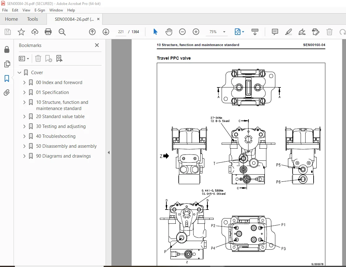
PPC valve 215
Valve control 238
Solenoid valve 240
PPC accumulator 242
Anti-drop valve for boom 244
Anti-drop valve for arm 250
Return oil filter 257
Attachment circuit selector valve 258
Hydraulic cylinder 260
Work equipment 265
Work equipment 266
Work equipment 266
Dimensions of arm 277
Dimensions of bucket 279
Cab and its attachments 283
Air conditioner piping 284
Electrical system 287
Electrical system 288
Engine control 288
Electrical control system 296
Monitor system 319
Sensor 346
KOMTRAX system 349
20 Standard value table 353
Standard service value table 353
Standard value table for engine related parts 354
Standard value table for chassis related parts 356
30 Testing and adjusting 375
Testing and adjusting, Part 1 375
Tools for testing, adjusting, and troubleshooting 377
Sketch of special tool 381
Testing engine speed 382
Testing intake air pressure (boost pressure) 383
Testing exhaust gas color 384
Adjusting valve clearance 385
Testing compression pressure 387
Testing blow-by pressure 388
Testing engine oil pressure 389
Handling fuel system parts 390
Releasing residual pressure from fuel system 390
Testing fuel pressure 391
Testing fuel delivery, return and leak amount 394
Bleeding air from fuel circuit 397
Checking fuel circuit for leakage 398
Checking and adjusting air conditioner compressor belt tension 399
Replacing fan belt 400
Testing swing circle bearing clearance 401
Checking and adjusting track shoe tension 402
Inspection and adjustment oil pressure in work equipment, swing, and travel circuits 404
Testing control circuit source pressure 407
Testing and adjusting oil pressure in pump PC control circuit 408
Testing and adjusting oil pressure in pump LS control circuit 411
Testing solenoid valve output pressure 416
Testing PPC valve output pressure 419
Adjusting play of work equipment and swing PPC valves 421
Checking parts which cause hydraulic drift of work equipment 422
Releasing residual pressure from hydraulic circuit 424
Testing oil leakage 425
Bleeding air from each part 428
Testing and charging accumulator (manufactured by NOK) nitrogen gas pressure for attachment (low pressure side) 430
Testing and charging accumulator nitrogen gas pressure for attachment (high pressure side) 432
Replacing accumulator bladder on high pressure side for accumulator piping 434
Checking cab tipping stopper 439
Adjusting mirrors 440
Installation and adjustment of mirrors 441
Angle adjustment of rear view camera 447
Testing and adjusting, Part 2 451
Special functions of machine monitor 452
Testing and adjusting, Part 3 509
Handling voltage circuit of engine controller 510
Preparation work for troubleshooting of electrical system 511
Procedure for testing diodes 516
Pm Clinic service 517
40 Troubleshooting 527
Failure code table and fuse locations 527
Failure codes table 528
Fuse locations 533
General information on troubleshooting 539
Points to remember when troubleshooting 540
Sequence of events in troubleshooting 541
Check before troubleshooting 542
Classification and procedures for troubleshooting 543
How to read electric wire code 547
Connection table for connector pin numbers 550
T- branch box and T- branch adapter table 586
Troubleshooting by failure code (Display of code), Part 1 591
Failure code [989L00] 593
Failure code [989M00] 594
Failure code [989N00] 595
Failure code [AA10NX] 596
Failure code [AB00KE] 598
Failure code [B@BAZG] 600
Failure code [B@BAZK] 601
Failure code [B@BCNS] 602
Failure code [B@BCZK] 603
Failure code [B@HANS] 604
Failure code [CA111] 605
Failure code [CA115] 606
Failure code [CA122] 607
Failure code [CA123] 609
Failure code [CA131] 611
Failure code [CA132] 614
Failure code [CA144] 616
Failure code [CA145] 618
Failure code [CA153] 620
Failure code [CA154] 622
Failure code [CA155] 624
Failure code [CA187] 626
Failure code [CA221] 628
Failure code [CA222] 630
Failure code [CA227] 632
Failure code [CA234] 634
Failure code [CA238] 636
Failure code [CA271] 638
Failure code [CA272] 640
Failure code [CA322] 642
Failure code [CA323] 644
Failure code [CA324] 646
Failure code [CA325] 648
Failure code [CA331] 650
Failure code [CA332] 652
Troubleshooting by failure code (Display of code), Part 2 655
Failure code [CA342] 657
Failure code [CA351] 658
Failure code [CA352] 662
Failure code [CA386] 664
Failure code [CA428] 666
Failure code [CA429] 668
Failure code [CA435] 670
Failure code [CA441] 672
Failure code [CA442] 676
Failure code [CA449] 678
Failure code [CA451] 680
Failure code [CA452] 682
Failure code [CA488] 684
Failure code [CA553] 685
Failure code [CA559] 686
Failure code [CA689] 688
Failure code [CA731] 691
Failure code [CA757] 693
Failure code [CA778] 696
Failure code [CA1633] 699
Failure code [CA2185] 700
Failure code [CA2186] 702
Failure code [CA2249] 704
Failure code [CA2311] 705
Failure code [CA2555] 707
Failure code [CA2556] 710
Failure code [D19JKZ] 713
Failure code [D862KA] 716
Failure code [DA22KK] 717
Failure code [DA25KP] 720
Failure code [DA25KP] 724
Failure code [DA29KQ] 728
Failure code [DA29KQ] 731
Troubleshooting by failure code (Display of code), Part 3 735
Failure code [DA2RMC] 737
Failure code [DAF8KB] 746
Failure code [DAFGMC] 748
Failure code [DAFRMC] 749
Failure code [DGH2KB] 756
Failure code [DHPAMA] 758
Failure code [DHPBMA] 761
Failure code [DHS3MA] 764
Failure code [DHS4MA] 767
Failure code [DHS8MA] 770
Failure code [DHSAMA] 773
Failure code [DHSBMA] 776
Failure code [DHSDMA] 779
Failure code [DHX1MA] 782
Failure code [DW43KA] 786
Failure code [DW43KB] 788
Failure code [DW45KA] 790
Failure code [DW45KB] 794
Failure code [DW91KA] 796
Failure code [DW91KB] 798
Failure code [DWA2KA] 800
Failure code [DWA2KB] 802
Failure code [DWK0KA] 804
Failure code [DWK0KB] 806
Troubleshooting by failure code (Display of code), Part 4 809
Failure code [DXA8KA] 811
Failure code [DXA8KB] 814
Failure code [DXA9KA] 816
Failure code [DXA9KB] 819
Failure code [DXE0KA] 821
Failure code [DXE0KB] 823
Failure code [DXE4KA] 825
Failure code [DXE4KB] 827
Failure code [DXE5KA] 829
Failure code [DXE5KB] 831
Failure code [DXE6KA] 833
Failure code [DXE6KB] 835
Failure code [DY20KA] 837
Failure code [DY20MA] 839
Failure code [DY2CKA] 841
Failure code [DY2CKB] 844
Failure code [DY2DKB] 846
Failure code [DY2EKB] 848
Troubleshooting of electrical system (E-mode) 851
Before troubleshooting for electrical system 853
Information described in troubleshooting table 855
E-1 When starting switch is turned to ON position, machine monitor displays nothing 857
E-2 When starting switch is turned to ON position (with engine stopped), basic check items light up 860
E-3 Engine does not start (engine does not crank) 863
E-4 Preheating system does not work 870
E-5 Automatic warm-up system does not work (in cold weather) 875
E-6 For all work equipment, swing, travel, or lock are not available 876
E-7 Caution item lights up while the engine is running 879
E-8 Emergency stop item lights up while the engine is running 886
E-9 Engine coolant temperature gauge does not indicate correct temperature 888
E-10 Hydraulic oil temperature gauge does not indicate correct temperature 890
E-11 Fuel gauge does not indicate correct level 893
E-12 Contents of display on machine monitor are different from actual machine condition 896
E-13 Some areas of machine monitor screen are not displayed 897
E-14 Function switch does not work 898
E-15 Auto-deceleration function does not work properly 899
E-16 Working mode does not change 901
E-17 Speed range does not change 902
E-18 Alarm buzzer does not stop sounding 904
E-19 Wiper or window washer does not operate 905
E-20 One-touch power maximizing function does not work properly 909
E-21 Swing parking brake does not work properly 913
E-22 Travel alarm does not sound or does not stop sounding 917
E-23 Air conditioner does not work properly (including air conditioner abnormality record) 921
E-24 Service meter is not displayed while the starting switch is turned off 940
E-25 Service mode cannot be selected 941
E-26 Lever operation signal is not displayed correctly with monitoring function 942
E-27 KOMTRAX system does not operate normally 954
Troubleshooting of hydraulic and mechanical system (H-mode) 957
Hydraulic and mechanical system diagram 960
Information described in troubleshooting table 962
H-1 Work equipment, swing and traveling speed are all slow, or there is no force 963
H-2 Engine speed drops significantly or engine stalls 966
H-3 All work equipment, swinging and traveling are not available 968
H-4 Unusual noise is heard from around hydraulic pump 969
H-5 Auto-deceleration function does not work 971
H-6 Fine control performance or response is poor 972
H-7 Boom speed or power is low 973
H-8 Arm speed or power is low 977
H-9 Bucket speed or power is low 981
H-10 Work equipment does not move in a single operation 983
H-11 Hydraulic drift of work equipment is significant 984
H-12 Time lag of work equipment is large 988
H-13 When certain work equipment is relieved hydraulically, other work equipment will move 990
H-14 One-touch power maximization function does not operate 991
H-15 When operations of work equipment are combined, equipment with heavier loads will move slower 992
H-16 Boom RAISE is slow during the Swing + Boom RAISE operation 993
H-17 When combining swing and travel operations, travel speed will drop significantly 994
H-18 Travel deviation is detected 995
H-19 Travel speed is slow 997
H-20 Machine is not steered well or steering power is low 1000
H-21 Travel speed does not change, or travel speed is too slow or fast 1004
H-22 One track does not run 1006
H-23 Machine does not swing 1008
H-24 Swing acceleration or swing speed is low 1011
H-25 Upper structure overruns excessively when it stops swinging 1014
H-26 Resulting shock is large when the upper structure stops swinging 1017
H-27 Unusual loud noise is heard when the upper structure stops swinging 1018
H-28 Swing hydraulic drift on a slope is significant 1019
H-29 Attachment circuit cannot be changed 1022
H-30 Oil flow in the attachment circuit cannot be changed 1023
Troubleshooting of engine (S-mode) 1025
Method of using troubleshooting chart 1028
S-1 Starting performance is poor 1032
S-2 Engine does not start 1033
S-3 Engine does not pick up smoothly 1036
S-4 Engine stops during operations 1037
S-5 Engine does not rotate smoothly 1038
S-6 Engine lack output (or lacks power) 1039
S-7 Exhaust smoke is black (incomplete combustion) 1040
S-8 Oil consumption is excessive (or exhaust smoke is blue) 1041
S-9 Oil becomes contaminated quickly 1042
S-10 Fuel consumption is excessive 1043
S-11 Oil is in coolant (or coolant spurts back or coolant level goes down) 1044
S-12 Oil pressure drops 1045
S-13 Oil level rises (Entry of coolant/fuel) 1046
S-14 Coolant temperature becomes too high (overheating) 1047
S-15 Abnormal noise is made 1048
S-16 Vibration is excessive 1049
50 Disassembly and assembly 1051
General information on disassembly and assembly 1051
How to read this manual 1052
Coating materials list 1054
Special tools list 1057
Sketches of special tools 1062
Engine and cooling system 1069
Removal and installation of fuel supply pump assembly 1070
Removal and installation of fuel injector assembly 1074
Removal and installation of engine front seal 1082
Removal and installation of engine rear seal 1085
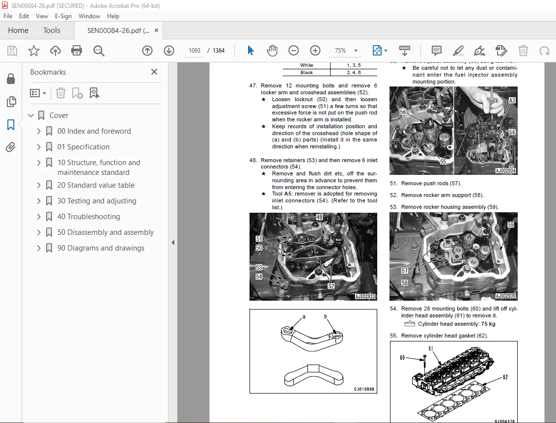
Removal and installation of cylinder head assembly 1088
Removal and installation of radiator assembly 1102
Removal and installation of hydraulic oil cooler assembly 1105
Removal and installation of aftercooler assembly 1107
Removal and installation of fuel cooler assembly 1110
Removal and installation of engine and hydraulic pump assembly 1111
Power train 1121
Removal and installation of final drive assembly 1122
Disassembly and assembly of final drive assembly 1124
Removal and installation of swing motor and swing machinery assembly 1149
Disassembly and assembly of swing motor and swing machinery assembly 1151
Removal and installation of swing circle assembly 1161
Undercarriage and frame 1163
Disassembly and assembly of carrier roller assembly 1164
Disassembly and assembly of track roller assembly 1167
Removal and installation of idler, recoil spring assembly 1169
Disassembly and assembly of idler assembly 1170
Disassembly and assembly of recoil spring assembly 1173
Removal and installation of sprocket 1175
Expansion and installation of track shoe assembly 1176
Removal and installation of revolving frame assembly 1178
Removal and installation of counterweight assembly 1180
Hydraulic system 1183
Removal and installation of center swivel joint assembly 1184
Disassembly and assembly of center swivel joint assembly 1186
Removal and installation of hydraulic tank assembly 1187
Removal and installation of control valve assembly 1191
Disassembly and assembly of control valve assembly 1196
Removal and installation of hydraulic pump assembly 1200
Removal and installation of oil seal in hydraulic pump input shaft 1204
Disassembly and assembly of work equipment PPC valve assembly 1205
Disassembly and assembly of travel PPC valve assembly 1207
Disassembly and assembly of hydraulic cylinder assembly 1210
Work equipment 1217
Removal and installation of work equipment assembly 1218
Removal and installation of anti- drop valve assembly for boom 1221
Removal and installation of anti- drop valve assembly for arm 1224
Disassembly and assembly of anti-drop valve assembly 1226
Cab and its attachments 1229
Removal and installation of operator’s cab assembly 1230
Removal and installation of operator cab glass (stuck glass) 1233
Removal and installation of front window assembly 1243
Removal and installation of floor frame assembly 1250
REMOVE AND INSTALL WORK EQUIPMENT CONTROL LEVER ASSEMBLY 1254
Electrical system 1269
Removal and installation of air conditioner unit assembly 1270
Removal and installation of KOMTRAX communication modem assembly 1273
Removal and installation of monitor assembly 1274
Removal and installation of pump controller assembly 1276
Removal and installation of engine controller assembly 1278
90 Diagrams and drawings 1281
Hydraulic diagrams and drawings 1281
Hydraulic circuit diagram 1283
Hydraulic circuit diagram (Boom RAISE) 1285
Hydraulic circuit diagram (Swing LEFT) 1287
Hydraulic circuit diagram (Boom RAISE + Swing LEFT) 1289
Hydraulic circuit diagram 1291
Hydraulic circuit diagram 1293
Electrical diagrams and drawings 1297
Electrical circuit diagram 1299
Electrical circuit diagram for air conditioner 1311
Connector/electrical wiring connection table 1313
Connector arrangement diagram 1343
Wiring harness diagram 1345
DESCRIPTION:
Komatsu PC200-8 PC200LC-8 PC220-8 PC220LC-8 Excavator Shop Manual SEN00084-26 – PDF DOWNLOAD
S.V 29/12/24


