Komatsu PC200-6 PC200LC-6 PC210-6 PC210LC-6 PC220-6 PC220LC-6 PC230-6 PC230LC-6 Shop Manual PDF
$39.95
Komatsu PC200-6 PC200LC-6 PC210-6 PC210LC-6 PC220-6 PC220LC-6 PC230-6 PC230LC-6 Excavator Shop Manual SEBM010106 – PDF DOWNLOAD
PC200, 200LC-6 STD 96514 and up
PC200, 200LC-6 HYPER GX 96514 and up
PC220, 220LC-6 STD 52852 and up
Description
Komatsu PC200-6 PC200LC-6 PC210-6 PC210LC-6 PC220-6 PC220LC-6 PC230-6 PC230LC-6 Excavator Shop Manual SEBM010106 – PDF DOWNLOAD
FILE DETAILS:
Komatsu PC200-6 PC200LC-6 PC210-6 PC210LC-6 PC220-6 PC220LC-6 PC230-6 PC230LC-6 Excavator Shop Manual SEBM010106 – PDF DOWNLOAD
Language : English
Pages : 1278
Downloadable : Yes
File Type : PDF
IMAGES PREVIEW OF THE MANUAL:
TABLE OF CONTENTS:
Komatsu PC200-6 PC200LC-6 PC210-6 PC210LC-6 PC220-6 PC220LC-6 PC230-6 PC230LC-6 Excavator Shop Manual SEBM010106 – PDF DOWNLOAD
PC200, 200LC-6 STD 96514 and up
PC200, 200LC-6 HYPER GX 96514 and up
PC220, 220LC-6 STD 52852 and up
MAIN MENU 0
COVER 1
CONTENTS 2
SAFETY 11
Safety Notice 11
FOREWORD 13
General 13
How to Read the Shop Manual 14
Hoisting Instructions 15
Method of Disassembling, Connecting Push-Pull Type Coupler 16
Coating Materials 18
Standard Tightening Torque 20
Electric Wire Code 23
Conversion Table 24
Units 30
01 GENERAL 31
Specification Dimension Drawings 32
Specifications 40
Weight Table 62
Fuel, Coolant and Lubricants 82
10 STRUCTURE AND FUNCTION 85
Engine Related Parts 86
Radiator, Oil Cooler, Aftercooler 88
Power Train 91
Final Drive 92
Swing Circle 93
Swing Machinery 94
Track Frame, Recoil Spring 95
Track Shoe 96
Hydraulic Piping Drawing 98
Hydraulic Circuit Diagram 102
Hydraulic Tank 106
Hydraulic Pump 107
Line Oil Filter 139
Control Valve 140
Self-reducing Pressure Valve 154
CLSS 159
Swing Motor 222
Center Swivel Joint 228
Travel Motor 230
Valve Control 238
Work Equipment, Swing PPC Valve 240
Travel PPC Valve 248
Service PPC Valve 252
Safety Lock Valve 256
PPC Accumulator 256
Straight-Travel System 257
Solenoid Valve 258
Boom Holding Valve 260
Additional Filter for Breaker 263
Swivel Joint for Arm Rotation 265
Arm Rotation Motor 266
Work Equipment 268
Air Conditioner 269
Actual Electric Wiring Diagram 270
Electrical Circuit Diagram 278
PC220-6 STD Serial No : 96514 – 102228 278
PC210-6 STD Serial No : 30980 – 31424 278
PC220-6 STD Serial No : 52852 – 53561 278
PC230-6 STD Serial No : 10177 – 10246 278
Engine Control System 292
Electronic Control System for STD 301
Electronic Control System for Hyper GX 341
Machine Monitor System 400
Sensors 411
Front Window Auto Pull-up System 414
20 TESTING AND ADJUSTING 417
TABLE OF JUDGEMENT STANDARD VALUE 420
TESTING AND ADJUSTING 445
Tools for Testing, Adjusting, and Troubleshooting 445
Measuring Engine Speed 446
Measuring Exhaust Gas Color 447
Adjusting Valve Clearance 448
Measuring Compression Pressure 449
Measuring Blow-by Pressure 449
Testing and Adjusting Fuel Injection Timing 450
Measuring Engine Oil Pressure 451
Testing and Adjusting Alternator Belt Tension 452
Testing and Adjusting Belt Tension for Air Conditioner Compressor 452
Measuring Speed Sensor 453
Testing and Adjusting Governor Motor Lever Stroke 454
Testing and Adjusting Hydraulic Pressure in Work Equipment, Swing, Travel Circuit 455
Testing and Adjusting PC Valve Output Pressure (Servo Piston Input Pressure) 458
Testing and Adjusting LS Valve Output Pressure (Servo Piston Input Pressure) and LS Differential Pressure 460
Testing and Adjusting Control Circuit Oil Pressure 463
Testing Solenoid Valve Output Pressure 465
Measuring PPC Valve Output Pressure 467
Measuring EPC Solenoid Valve Output Pressure and Checking EPC Shuttle Valve 469
Adjusting Work Equipment, Swing PPC Valve 471
Testing Travel Deviation 472
Testing Locations Causing Hydraulic Drift of Work Equipment 473
Measuring Oil Leakage 475
Releasing Remaining Pressure in Hydraulic Circuit 477
Testing Clearance of Swing Circle Bearing 478
Testing and Adjusting Track Shoe Tension 479
Bleeding Air 480
Input/Output Structure of GX Controller 483
Basic Operation and GX Function 484
Special Functions on GX Panel (Background Mode) 486
Check Procedure when Operation of GX Automatic Function is Defective 509
Adjusting Swing Back Prevention Function (Swing Teaching Mode) 511
Bucket Dimension Input Mode when Using Custom Bucket 513
Procedure for Replacing Sensor 516
TROUBLESHOOTING 522
Points to Remember When Troubleshooting 523
Sequence of Events in Troubleshooting 524
Precautions When Carrying Out Maintenance 525
Checks Before Troubleshooting 533
Connector Types and Mounting Locations 535
Connection Table for Connector Pin Numbers 543
Explanation of Control Mechanism for Electrical System 555
Display Method and Special Functions of Monitor Panel 557
Method of Using Judgement Table 567
Method of Using Troubleshooting Charts 569
Details of Troubleshooting and Troubleshooting Procedure 571
Troubleshooting of Communication Abnormality System ( N Mode) 578
N-1 (E218) Communications Abnormality 579
Troubleshooting of Engine Throttle – Pump Controller (Govenor Control System) (E Mode) 582
Points to Remember When Carrying Out Troubleshooting of Engine Throttle – Pump Controller System 583
Action Taken by Controller When Abnormality Occurs and Problems on Machine 585
Judgement Table for Engine Throttle – Pump Controller (Govenor Control System) and Engine Related Parts 589
Electrical Circuit Diagram for E Mode System 591
E-1 Abnormality in Engine Throttle – Pump Controller Power Source (controller LED is OFF) 593
E-2 (E308) Abnormality in Fuel Control Dial Imput Value is Displayed 594
E-3 (E317) Abnormality (disconnection) in Motor Drive System is Displayed 595
E-4 (E318) Abnormality (short circuit) in Motor Drive System is Displayed 596
E-5 (E306) Abnormality in Feedback Potentionmeter System is Displayed 597
E-6 (E315) Abnormality (short circuit) in Battery Relay Output System is Displayed 598
E-7 (E316) Abnormality (step-out) in Motor is Displayed 599
E-8 Engine Does Not Start 601
E-9 Engine Speed is Irregular 605
a) Idling Speed is Irregular 605
b) There is Hunting 607
E-10 Lack of Output (engine high idling speed is too low) 609
E-11 Engine Does Not Stop 611
E-12 Defective Operation of Battery Relay System (engine does not stop) 613
Troubleshooting of Engine System (S Mode) 616
Method of Using Troubleshooting Charts 617
S-1 Starting Performance is Poor (starting always takes time) 621
S-2 Engine Does Not Start 622
(1) Engine Does Not Turn 622
(2) Engine Turns But no Exhaust Smoke Comes Out (fuel is not being injected) 623
(3) Exhaust Smoke Comes Out but Engine Does Not Start (fuel is being injected) 624
S-3 Engine Does Not Pick Up Smoothly (follow-up is poor) 625
S-4 Engine Stops During Operation 626
S-5 Engine Does Not Rotate Smoothly (hunting) 627
S-6 Engine Lacks Output ( no power) 628
S-7 Exhaust Smoke is Black (incomplete combustion) 629
S-8 Oil Consumption is Excessive (or exhaust smoke is blue) 630
S-9 Oil Becomes Contaminated Quickly 631
S-10 Fuel Consumption is Excessive 632
S-11 Oil is in Cooling Water, or Water Spurts Back, or Water Level Goes Down 633
S-12 Oil Pressure Caution Lamp Lights Up (drop in oil pressure) 634
S-13 Oil Level Rises (water, fuel in oil) 635
S-14 Water Temperature Becomes Too High (overheating) 636
S-15 Abnormal Noise is Made 637
S-16 Vibration is Excessive 638
Troubleshooting of Engine Throttle – Pump Controller (Pump Control System) (C Mode) 640
Points to Remember When Troubleshooting Pump Controller System 641
Action Taken by Controller When Abnormality Occurs and Problems on Machine 643
Judgement Table for Engine Throttle – Pump Controller (pump control system) and Hydraulic Related Parts 651
Electrical Circuit Diagram for C Mode 653
C-1 Abnormality in Controller Power Source System (controller LED is OFF) 657
C-2 (E232) Short Circuit in PC-EPC Solenoid System is Displayed 658
C-3 (E233) Disconnection in PC-EPC Solenoid System is Displayed 659
C-4 (E203) Short Circuit in Swing Brake Solenoid System is Displayed 660
C-5 (E213) Disconnection in Swing Brake Solenoid System is Displayed 662
C-6 (E204) Short Circuit in Pump Merge/Divider Solenoid System is Displayed 664
C-7 (E214) Disconnection in Pump Merge/Divider Solenoid System is Displayed 665
C-8 (E207) Short Circuit In Active Mode Solenoid System is Displayed 666
C-9 (E208) Disconnection in Active Mode Solenoid System is Displayed 667
C-10 (E206) Short Circuit in Travel Speed Solenoid System is Displayed 668
C-11 (E216) Disconnection in Travel Speed Solenoid System is Displayed 669
C-12 (E205) Short Circuit in 2-Stage Relief Solenoid System is Displayed 670
C-13 (E215) Disconnection in 2-State Relief Solenoid System is Displayed 671
C-14 (E217) Model Selection Input Error is Displayed 672
C-15 (E222) Short Circuit in LS-EPC Solenoid System is Displayed 674
C-16 (E223) Disconnection in LS-EPC Solenoid System is Displayed 675
C-17 (E224) Abnormality in Front Pump Pressure Sensor System is Displayed 676
C-18 (E225) Abnormality in Rear Pump Pressure Sensor System is Displayed 677
C-19 (E226) Abnormality in Pressure Sensor Power Source System is Displayed 678
C-20 (E227) Abnormality in Engine Speed Sensor System is Displayed 679
C-21 (E302) Short Circuit in Swing Stroke Limit Solenoid System is Displayed 680
C-22 (E303) Disconnection in Swing Stroke Limit Solenoid System is Displayed 681
Troubleshooting of Engine throttle – Pump Controller (Input Signal System) (F Mode) 682
Electrical Circuit Diagram for F Mode 683
F-1 Bit Pattern 20-(1) Swing Oil Pressure Switch Does Not Light Up 687
F-2 Bit Pattern 20-(2) Travel Oil Pressure Switch Does Not Light Up 688
F-3 Bit Pattern 20-(3) Boom LOWER Oil Pressure Switch Does Not Light Up 689
F-4 Bit Pattern 20-(4) Boom RAISE Oil Pressure Switch Does Not Light Up 690
F-5 Bit Pattern 20-(5) Arm IN Oil Pressure Switch Does Not Light Up 691
F-6 Bit Pattern 20-(6) Arm OUT Oil Pressure Switch Does Not Light Up 692
F-7 Bit Pattern 21-(1) Bucket CURL Oil Pressure Switch Does Not Light Up 693
F-8 Bit Pattern 21-(2) Bucket DUMP Oil Pressure Switch Does Not Light Up 694
F-9 Bit Pattern 21-(3) Swing Lock Switch Does Not Light Up 695
F-10 Bit Pattern 22-(5) Kerosene Mode Connection Does Not Light Up 696
F-11 Bit Pattern 22 (6) L H Knob Switch Does Not Light Up 697
Troubleshooting of Hydraulic and Mechanical system (H Mode) 698
Table of Failure Modes and Causes for Hydraulic and Mechnaical Systems 699
Pump Merge/Divider Logic 703
Solenoid Actuation Table 704
Troubleshooting Flow Charts for Each Failure Mode 705
All Work Equipment, Travel, Swing 705
H-1 Speeds of All Work Equipment, Swing, Travel Are Slow or Lack Power 705
H-2 There is Excessive Drop in Engine Speed, or Engine Stalls 707
H-3 No Work Equipment, Travel, Swing Move 708
H-4 Abnormal Noise Generated (around pump) 708
H-5 Auto-Deceleration Does Not work (PPC shuttle valve is euqipped only in travel PPC valve) 709
H-6 Fine Control Ability is Poor or Response is Poor 709
Work Equipment 711
H-7 Boom is Slow or Lacks Power 711
H-8 Arm is Slow or Lacks Power 713
H-9 Bucket is Slow or Lacks Power 715
H10- Work Equipment (boom, arm, bucket) Does Not Move (but travel and swing are normal) 716
H-11 Excessive Hydraulic Drift 716
H-12 Excessive Time Lag (engine at low idling) 717
H-13 Other Equipment Moves When Single Circuit is Relieved 717
H-14 Lack of Power When Pressure Rises 718
H-15 In L/O, F/O Modes, Work Equipment Speed is Faster Than Specified Speed 719
Compound Operations 719
H-16 In Compound Operations, Work Equipment with Larger Load is Slow 719
H-17 In Swing + Boom RAISE, Boom RAISE is Slow 720
H-18 In Swing + Travel, Travel Speed Drops Excessively 720
Travel System 721
H-19 Travel Deviation 721
H-20 Travel Speed is Slow 723
H-21 Steering Does Not Turn Easily or Lacks Power 725
H-22 Travel Speed Does Not Switch or is Faster than Specified Speed 727
H-23 Travel Does Not Move (one side only) 727
Swing System 728
H-24 Does Not Swing 728
H-25 Swing Acceleration is Poor or Swing Speed is Slow 729
H-26 Excessive Overrun When Stopping Swing 731
H-27 Excessive Shock When Stopping Swing (one direction only) 732
H-28 Excessive Abnormal Noise When Stopping Swing 732
H-29 Excessive Hydraulic Drift of Swing 733
H-30 Swing Speed is Faster than Specified Speed in L/O and F/O Modes 734
H-31 Operation of Automatic Mode is Defective (HYPER specification) 734
Troubleshooting of Machine Monitor System (M Mode) 736
Action Taken by Monitor Panel When Abnormality Occurs and Problems on Machine 739
Electrical Circuit Diagram for M Mode System 741
M-1 (E101) Abnormality in Error Data is Displayed 743
M-1 (E102) Error in Clock Data is Displayed 743
M-2 (E103) Short Circuit in Buzzer Output or Contact of 24V Wiring Harness with Buzzer Drive Harness is Displayed 744
M-3 (E104) Air Cleaner Clogging Detected is Displayed 745
M-4 (E108) Engine Water Temperature 105 degrees C Detected is Displayed 745
M-5 When Starting Switch is Turned ON, None of Lamps on Monitor Panel Light Up for 3 Seconds 746
a) None of Lamps on Monitor Panel Light Up 746
b) Some of Lamps on Monitor Panel Do Not Light Up 746
M-6 When Starting Switch is Turned ON, Monitor Panel Lamps All Stay Lighted Up and Do Not Go Out 748
M-7 When Starting Switch is Turned ON, Items Lighted Up on Monitor Palen are Different from Actual Machine (Model) 748
M-8 When Starting Switch is Turned ON (engine stopped), Basic Check Items Flash 749
a) Coolant Level Flashes 749
b) Engine Oil Level Flashes 750
c) Hydraulic Oil Level Flashes 751
M-9 Preheating is Not Being Used But Preheating Monitor Lights Up 752
M-10 When Starting Switch is Turned ON and Engine is Started, Basic Check Items Flash 753
a) Alternator System 753
b) Engine Oil Pressure System 754
M-11 When Starting Switch is Turned ON (engine stopped), Caution Items, Emergency Items Flash (battery, engine oil pressure l 755
a) Alternator System 755
b) Engine Oil Pressure Sensor System 756
M-12 When Starting Switch is Turned ON and Engine is Started, Caution Items, Emergency Items Flash (when there is no abnormal 757
a) Engine Oil Pressure Flashes 757
b) Coolant Level Flashes 757
c) Battery Charge Flashes 757
d) Coolant Temperature Flashes 758
e) Fuel Level Flashes 758
f) Air Cleaner Clogging Flashes 759
M-13 When Starting Switch is Turned ON (engine stopped), Buzzer Does Not Sound for 1 Second; Caution Item Flashes but Buzzer 760
M-14 No Abnormality is Displayed on Monitor but Buzzer Sounds 760
M-15 Night Lighting on Monitor Panel Does Not Light Up (liquid crystal display is normal) 761
M-16 Coolant Temperature Gauge Does Not Rise 762
M-17 Coolant Temperature Gauge Does Not Give Any Display (none of gauge lamps light up during operation) 762
M-18 Fuel Level Gauge Always Displays FULL 763
M-19 Fuel Level Gauge Does Not Give Display 763
M-20 Swing Lock Switch is Turned ON (LOCK) but Swing Lock Monitor Does Not Light Up 764
M-21 Swing Prolix Switch is Turned ON (prolix), but Swing Lock Monitor Does Not Flash 764
M-22 Service Meter Does Not Advance While Engine is Running 765
M-23 When Starting Switch is at OFF and Time Switch is Pressed, Time and Service Meter Are Not Displayed 765
M-24 Defective Fuel Level Sensor System 766
M-25 Defective Coolant Temperature Sensor System 767
M-26 Defective Engine Oil Level Sensor System 768
M-27 Defective Coolant Level Sensor System 769
M-28 Defective Hydraulic Oil Level Sensor System 770
M-29 Wiper Does Not Work, or Switch is Not Being Used but Wiper is Actuated 771
a) Wiper Does Not Work 771
b) Wiper Switch is Not Being Operated but Wiper is Actuated 774
M-30 Washer Motor Does Not Work, or Switch is Not Being Used but Washer Motor is Actuated 776
a) Washer Motor Does Not Work 776
b) Switch is Not Being Operated but Washer is Actuated 777
Troubleshooting of GX Controller System (A Mode) 778
Points to Remember When Troubleshooting GX Controller System 780
Procedure for Troubleshooting Hyper GX 781
Operation of GX Error Code Display Mode and Content of Display 784
Action Taken by Controller When Abnormality Occurs, and Problems on Machine 787
Electrical Wiring Diagram for GX Controller 795
A-1 E6:01, E6:02, E6:03, and E6:04 are Displayed at the Same Time 797
A-2 E6:01 (GX panel 011, 012) [Abnormality in Boom (RAISE) Pressure Sensor System] is Displayed 799
A-3 E6:01 (GX panel 013, 014) [Abnormality in Boom (LOWER) Pressure Sensor System] is Displayed 801
A-4 E6:02 (GX panel 021, 022) [Abnormality in Arm (IN) Pressure Sensor System] is Displayed 803
A-5 E6:02 (GX panel 023, 024) [Abnormality in Arm (OUT) Pressure Sensor System] is Displayed 805
A-6 E6:03 (GX panel 031, 032) [Abnormality in Bucket (CURL) Pressure Sensor System] is Displayed 807
A-7 E6:03 (GX panel 033, 034) [Abnormality in Bucket (DUMP) Pressure Sensor System] is Displayed 809
A-8 E6:04 (GX panel 041, 042) [Abnormality in Swing (RIGHT) Pressure Sensor System] is Displayed 811
A-9 E6:04 (GX panel 043, 044) [Abnormality in Swing (LEFT) Pressure Sensor System] is Displayed 813
A-10 E6:06 (GX panel 061, 063) [Abnormality in Clinometer Input Valve] is Displayed 815
A-11 E6:07 and E6:08 [Abnormality in Potentiometer Power Source] are Displayed at the Same Time 817
A-12 E6:07 (GX panel 071, 072) [Abnormality in Boom Potentionmeter System] is Displayed 819
A-13 E6:08 (GX panel 081, 082) [Abnormality in Arm Potentiometer System] is Displayed 821
A-14 E6:11 (GX panel 111, 112) [Abnormality in Boom Variable Angle] is Displayed 823
A-15 E6:12 (GX panel 121, 122) [Abnormality in Arm Variable Angle] is Displayed 825
A-16 E6:13 (GX panel 131, 132) [Abnormality in Bucket Variable Angle] is Displayed 828
A-17 E6:14 (GX panel 141) [Abnormality in Comparision of Two Boom Sensor Signals] is Displayed 829
A-18 E6:15 (GX panel 151) [Abnormality in Comparision of Two Arm Sensor Singals] is Displayed 830
A-19 E6:16 (GX panel 163) [No Change in Signal When Work Equipment Should Move] is Displayed 831
A-20 E6:17 (GX panel 171, 172) [Cutting Edge Position Out of Range] is Displayed 832
A-21 E6:18 (GX panel 181, 182) [Abnormality in Data ROM] is Displayed 832
A-22 E6:21 (GX panel 211, 212, 213, 214) [Abnromality in Engine Pick-up] is Displayed 833
A-23 E6:22 (GX panel 221) [Change in Wiring Harness After Engine Picks up] is Displayed 837
A-23 E6:22 (GX panel 222) [Automatic Operation Disconnection Switch Signal Does Not Match in Valve Controller and GX Control 837
A-23 E6:22 (GX panel 223) [Abnormality in Controller Power Source] is Displayed 837
A-24 E6:23 (GX panel 231) [Abnormality in Remote Singal] is Displayed 841
A-24 E6:23 (GX panel 235) [Abnormality in 12V Power Source (overcurrent detection)] is Displayed 841
A-24 E6:23 (GX panel 236) [Abnormality in 24V Power Source (overcurrent detection)] is Displayed 841
A-25 E6:24 (GX panel 241) [Abnormality in Buzzer Drive System] is Diaplayed 844
A-26 E6:25 (GX panel 251, 252) [Impossible to Receive Network (S-NET) Signal] is Displayed 845
A-26 E6:25 (GX panel 253) [Impossible to Receive Network (HS-NET) Signal] is Displayed 847
A-27 E6:26 (GX panel 261, 262, 263, 264) [Abnormality in Non-Volatile Memory Data Range] is Displayed 850
A-28 E6:27 [Non-Volatile Read Error] is Displayed 851
A-29 E6:28 [Non-Volatile Write Error] is Displayed 851
A-30 Buzzer Does Not Sound (when there is no abnormal display) 852
A-31 Automatic Mode is Not Actuated When Knob Switch is Pressed (when there is no abnormal display 853
Troubleshooting of Valve Controller System (K Mode) 854
Points to Remember When Troubleshooting Valve Controller System 856
Action Taken by Controller When Abnormality Occurs and Problems on Machine 857
Judgement Table for Valve Controller System 875
Electrical Circuit Diagram of Valve Controller System 877
K-1 [LED OFF] Controller Power Source System 880
K-2 [E4:02] L H Knob Switch OFF System is Displayed 881
K-3 [E4:07] Abnormality in Model Code Input is Displayed 882
K-4 [E4:51] Abnormality in S-NET Communication is Displayed 883
1 Disconnection Related 883
2 Short Circuit Related 885
K-5 [E4:56] Abnormality in Teaching, Playback RAM Data is Displayed 885
K-6 [E4:57] Abnormality in Knob Switch is Displayed 886
K-7 [E4:01] Abnormality in Control Lever Neutral System is Displayed 887
K-8 [E4:04] Abnormality in Control Lever Potentiometer Power Source System is Displayed 889
K-9 [E4:11) Short Circuit in EPC Relay 1 Drive Power Source System is Displayed 890
K-10 [E4:12] Contact Between Chassis Power Source and EPC Relay 1 Drive Power Source System is Displayed 891
K-11 [E4:13] Short Circuit in EPC Relay 2 Drive Power Source System is Displayed 892
K-12 [E4:14] Contact Between Chassis Power Source and EPC Relay 2 Drive Power Source System is Displayed 893
K-13 [E4:15] Disconnection in EPC Relay 1,2 Solenoid Power Source System is Displayed 894
K-14 [E4:16] EPC Relay 1 Points Melted or Short Circuit in Solenoid Power Source System is Displayed 896
K-14 [E4:17] EPC Relay 2 Points Melted or Short Circuit in Solenoid Power Source System is Displayed 896
1) When E4:16 is Displayed Independently 896
2) When E4:16, E4:17 are Displayed Simultaneously 896
K-15 [E4:17] EPC Relay 2 Points Melted or Short Circuit in Solenoid Power Source System is Displayed 898
K-15 [E4:16] EPC Relay 1 Points Melted or Short Circuit in Solenoid Power Source System is Displayed 898
1) When E4:17 is Displayed Independently 898
2) When E4:16, E4:17 are Displayed Simultaneously 898
K-16 [E4:18] Abnormality in Lever Signal Input Delay Circuit System is Displayed 900
K-17 [E4:21] Abnormality 1 in Drive Circuit System for Boom LOWER EPC Valve is Displayed 901
K-17 [E4:25] Abnormality 1 in Drive Circuit System for Boom RAISE EPC Valve is Displayed 901
K-17 [E4:21] [E4:31] Abnormality 1,2 in Drive Circuit System for Boom LOWER EPC Valve is Displayed 903
K-17 [E4:25] [E4:35] Abnormality 1,2 in Drive Circuit System for Boom RAISE EPC Valve is Displayed 903
K-18 [E4:31 Abnormality 2 in Drive Circuit System for Boom LOWER EPC Valve is Displayed 905
K-18 [E4:35] Abnormality 2 in Drive Circuit System for Boom RAISE EPC Valve is Displayed 905
K-18 [E4:21] [E4:31] Abnormality 1,2 in Drive Circuit System for Boom LOWER EPC Valve is Displayed 907
K-18 [E4:25] [E4:35} Abnormality 1,2 in Drive Circuit System for Boom RAISE EPC Valve is Displayed 907
K-19 [E4:32} Abnormality 2 in Drive Circuit System for Arm IN EPC Valve is Displayed 909
K-19 [E4:33] Abnormality 2 in Drive Circuit System for Bucket CURL EPC Valve is Displayed 909
K-19 [E4:34] Abnormality 2 in Drive Circuit System for Swing LEFT EPC Valve is Displayed 909
K-19 [E4:36] Abnormality 2 in Drive Circuit System for Arm OUT LEFT EPC Valve is Displayed 909
K-19 [E4:37] Abnormality 2 in Drive Circuit System for Bucket DUMP EPC Valve is Displayed 909
K-19 [E4:38] Abnormality 2 in Drive Circuit System for Swing RIGHT EPC Valve is Displayed 909
K-19 [E4:22] [E4:32] Abnormality 1,2 in Drive Circuit System for Arm IN EPC Valve is Displayed 911
K-19 [E4:23] [E4:33] Abnormality 1,2 in Drive Circuit System for Bucket CURL EPC Valve is Displayed 911
K-19 [E4: 24] [E4:34] Abnormality 1,2 in Drive Circuit System for Swing LEFT EPC Valve is Displayed 911
K-19 [E4:26] [E4:36] Abnormality 1,2 in Drive Circuit System for Arm OUT EPC Valve is Displayed 911
K-19 [E4:27] [E4:37] Abnormality 1,2 in Drive Circuit System for Bucket DUMP EPC Valve is Displayed 911
K-19 [E4:28] [E4:38] Abnormality 1,2 in Drive Circuit System for Swing RIGHT EPC Valve is Displayed 911
K-20 [E4:41] [E4:42] [E4:43] [E4:44} Over-range in Control Lever Potentiometer Signal System is Displayed 913
K-21 [E4:45] [E4:46] [E4:47] [E4:48] Excessive Error in Signal SIG and Switch SIG of Control Lever Potentiometer is Displayed 915
K-22 [E4:55] Abnormality in ROM, RAM of CPU is Displayed 917
K-23 [E4:58] Abnormality in Interlock PLD is Displayed 917
K-24 [E4:22] Abnormality 1 in Drive Circuit System for Arm IN EPC Valve is Displayed 918
K-24 [E4:23] Abnormality 1 in Drive Circuit System for Bucket CURL EPC Valve is Displayed 918
K-24 [E4:24] Abnormality 1 in Drive Circuit System for Swing LEFT EPC Valve is Displayed 918
K-24 [E4:26] Abnormality 1 in Drive Circuit System for Arm OUT EPC Valve is Displayed 918
K-24 [E4:27] Abnormality 1 in Drive Circuit System for Bucket DUMP EPC Valve is Displayed 918
K-24 [E4:28] Abnormality 1 in Drive Circuit System for Swing RIGHT EPC Valve is Displayed 918
K-24 [E4:22] [E4:32] Abnormality 1,2 in Drive Circuit System for Arm IN EPC Valve is Displayed 920
K-24 [E4:23] [E4:33] Abnormality 1,2 in Drive Circuit System for Bucket CURL EPC Valve is Displayed 920
K-24 [E4:24] [E4:34] Abnormality 1,2 in Drive Circuit System for Swing LEFT EPC Valve is Displayed 920
K-24 [E4:26] [E4:36] Abnormality 1,2 in Drive Circuit System for Arm OUT EPC Valve is Displayed 920
K-24 [E4:27] [E4:37] Abnormality 1,2 in Drive Circuit System for Bucket DUMP EPC Valve is Displayed 920
K-24 [E4:28] [E4:38] Abnormality 1,2 in Drive Circuit System for Swing RIGHT EPC Valve is Displayed 920
30 DISASSEMBLY AND ASSEMBLY 922
Method of Using Manual 924
Precautions When Carrying Out Operation 925
Special Tool List 927
Sketches of Special Tools 935
Starting Motor 938
Removal of Starting Motor Assembly 938
Installation of Starting Motor Assembly 938
Alternator 939
Removal of Alternator Assembly 939
Installation of Alternator Assembly 940
Air Conditioner Compressor 942
Removal of Air Conditioner Compressor Assembly 942
Installation of Air Conditioner Compressor Assembly 942
Condenser 943
Removal of Condenser Assembly 943
Installation of Condenser Assembly 943
Air Conditioner Condenser 944
Removal of Air Conditioner Condenser Assembly 944
Installation of Air Conditioner Condenser Assembly 944
Dry Receiver 945
Removal of Dry Receiver Assembly 945
Installation of Dry Receiver Assembly 945
Engine Oil Cooler Core 946
Removal of Engine Oil Cooler Core Assembly 946
Installation of Engine Oil Cooler Core Assembly 946
Fuel Injection Pump 947
Removal of Fuel Injection Pump Assembly 947
Installation of Fuel Injection Pump Assembly 950
Water Pump 957
Removal of Water Pump Assembly 957
Installation of Water Pump Assembly 958
Nozzle Holder 959
Removal of Nozzle Holder Assembly 959
Installation of Nozzle Holder Assembly 959
Turbocharger 960
Removal of Turbocharger Assembly 960
Installation of Turbocharger Assembly 960
Thermostat 961
Removal of Thermostat Assembly 961
Installation of Thermostat Assembly 962
Govenor Motor 963
Removal of Govenor Motor Assembly 963
Installation of Governor Motor Assembly 963
Cylinder Head 964
Removal of Cylinder Head Assembly 964
Installation of Cylinder Head Assembly 970
Hydraulic Oil Cooler 981
Removal of Hydraulic Oil Cooler Assembly 981
Installation of Hydraulic Oil Cooler Assembly 981
Radiator – Hydraulic Oil Cooler 983
Removal of Radiator, Hydraulic Oil Cooler Assembly 983
Installation of Radiator, Hydraulic Oil Cooler Assembly 985
Engine – Main Pump 989
Removal of Engine, Main Pump Assembly 989
Installation of Engine, Main Pump Assembly 993
Damper 994
Removal of Damper Assembly 994
Installation of Damper Assembly 994
Fuel Tank 995
Removal of Fuel Tank Assembly 995
Installation of Fuel Tank Assembly 995
Center Swivel Joint 996
Removal of Center Swivel Joint Assembly 996
Installation of Center Swivel Joint Assembly 997
Disassembly of Center Swivel Joint Assembly 998
Assembly of Center Swivel Joint Assembly 998
Final Drive 999
Removal of Final Drive Assembly 999
Installation of Final Drive Assembly 999
Disassembly of Final Drive Assembly 1000
Assembly of Final Drive Assembly 1003
Travel Motor 1008
Disassembly of Travel Motor Assembly 1008
Assembly of Travel Motor Assembly 1014
Sprocket 1022
Removal of Sproket 1022
Installation of Sprocket 1022
Swing Motor and Swing Machinery 1023
Removal of Swing Motor, Swing Machinery Assembly 1023
Installation of Swing Motor, Swing Machinery Assembly 1024
Disassembly of Swing Machinery Assembly 1025
Assembly of Swing Machinery Assembly 1029
Swing Motor 1034
Disassembly of Swing Motor Assembly 1034
Assembly of Swing Motor Assembly 1038
Revolving Frame 1046
Removal of Revolving Frame Assembly 1046
Installation of Revolving Frame Assembly 1047
Swing Circle 1048
Removal of Swing Circle Assembly 1048
Installation of Swing Circle Assembly 1049
Idler – Recoil Spring 1050
Removal of Idler – Recoil Spring Assembly 1050
Installation of Idler – Recoil Spring Assembly 1050
Recoil Spring 1051
Disassembly of Recoil Spring Assembly 1051
Assembly of Recoil Spring Assembly 1052
Idler 1053
Disassembly of Idler Assembly 1053
Assembly of Idler Assembly 1054
Track Roller 1056
Removal of Track Roller Assembly 1056
Installation of Track Roller Assembly 1056
Disassembly of Track Roller Assembly 1057
Assembly of Track Roller Assembly 1059
Carrier Roller 1061
Removal of Carrier Roller Assembly 1061
Installation of Carrier Roller Assembly 1061
Disassembly of Carrier Roller Assembly 1062
Assembly of Carrier Roller Assembly 1064
Track Shoe 1066
Removal of Track Shoe Assembly 1066
Installation of Track Shoe Assembly 1066
Hydraulic Tank 1067
Removal of Hydraulic Tank Assembly 1067
Installation of Hydraulic Tank Assembly 1068
Main Pump 1069
Removal of Main Pump Assembly 1069
Installation of Main Pump Assembly 1071
Disassembly of Main Pump Assembly 1073
Assembly of Main Pump Assembly 1086
Main Pump Input Shaft Oil Seal 1102
Removal of Main Pump Input Shaft Oil Seal 1102
Installation of Main Pump Input Shaft Oil Seal 1102
Control Valve 1103
Removal of Control Valve Assembly 1103
Installation of Control Valve Assembly 1105
Disassembly of Control Valve Assembly 1106
Assembly of Control Valve Assembly 1111
Pump Merge-Divider Valve 1117
Disassembly of Pump Merge-Divider Valve Assembly 1117
Assembly of Pump Merge-Divider Valve Assembly 1117
Main Relief Valve 1118
Disassembly of Main Relief Valve Assembly 1118
Assmebly of Main Relief Valve Assembly 1118
Work Equipment EPC Valve 1119
Removal of Work Equipment EPC Valve Assembly 1119
Installation of work Equipment EPC Valve Assembly 1119
PC Valve 1120
Removal of PC Valve Assembly 1120
Installation of PC Valve Assembly 1121
LS Valve 1122
Removal of LS Valve Assembly 1122
Installation of LS Valve Assembly 1122
PC, LS-EPC Valve 1123
Removal of PC, LS-EPC Valve Assembly 1123
Installation of PC, LS-EPC Valve Assembly 1123
Solenoid Valve 1124
Removal of Solenoid Valve Assembly 1124
Installation of Solenoid Valve Assembly 1124
Work Equipment – Swing PPC Valve 1125
Removal of Work Equipment – Swing PPC Valve Assembly 1125
Installation of Work Equipment – Swing PPC Valve Assembly 1125
Disassembly of Work Equipment – Swing PPC Valve Assembly 1126
Assembly of Work Equipment – Swing PPC Valve Assembly 1127
Travel PPC Valve 1128
Removal of Travel PPC Valve Assembly 1128
Installation of Travel PPC Valve Assembly 1128
Disassembly of Travel PPC Valve Assembly 1129
Assembly of Travel PPC Valve Assembly 1130
Boom Lock Valve 1131
Removal of Boom Lock Valve Assembly 1131
Installation of Boom Lock Valve Assembly 1131
Boom Cylinder 1132
Removal of Boom Cylinder Assembly 1132
Installation of Boom Cylinder Assembly 1133
Arm Cylinder 1134
Removal of Arm Cylinder Assembly 1134
Installation of Arm Cylinder Assembly 1135
Bucket Cylinder 1136
Removal of Bucket Cylinder Assembly 1136
Installation of Bucket Cylinder Assembly 1137
Hydraulic Cylinder 1138
Disassembly of Hydraulic Cylinder Assembly 1138
Assembly of Hydraulic Cylinder Assembly 1141
Work Equipment 1145
Removal of Work Equipment Assembly 1145
Installation of Work Equipment Assembly 1146
Bucket 1147
Removal of Bucket Assembly 1147
Installation of Bucket Assembly 1148
Arm 1149
Removal of Arm Assembly 1149
Installation of Arm Assembly 1150
Bucket – Arm 1151
Removal of Bucket – Arm Assembly 1151
Installation of Bucket – Arm Assmebly 1152
Boom 1153
Removal of Boom Assembly 1153
Installation of Boom Assembly 1154
Opeator’s Cab 1155
Removal of Operator’s Cab Assembly 1155
Installation of Operator’s Cab Assembly 1156
Counterweight 1157
Removal of Counterweight Assembly 1157
Installation of Counterweight Assembly 1157
Work Equipment Electric Lever Unit 1159
Removal of Work Equipment Electric Lever Unit Assembly 1159
Installation of Work Equipment Electric Lever Unit Assembly 1159
Engine Throttle – Pump Controller 1160
Removal of Engine Throttle – Pump Controller Assembly 1160
Installation of Engine Throttle – Pump Controller Assembly 1160
Control Stand Case 1161
Removal of Control Stand Case 1161
Installation of Control Stand Case 1162
Valve Controller 1163
Removal of Valve Controller Assembly 1163
Installation of Valve Controller Assembly 1163
Monitor 1164
Removal of Monitor Assembly 1164
Installation of Monitor Assembly 1164
ITERMS FOR HYPER GX 1165
Swing Motor 1165
Removal of Swing Motor Assembly 1165
Installation of Swing Motor Assembly 1165
Control Valve 1166
Removal of Control Valve Assembly 1166
Installation of Control Valve Assembly 1167
Work Equipment EPC Valve 1168
Removal of Work Equipment EPC Valve Assembly 1168
Installation of Work Equipment EPC Valve Asembly 1168
Boom Cylinder 1169
Removal of Boom Cylinder Assembly 1169
Installation of Boom Cylinder Assembly 1170
Arm Cylinder 1171
Removal of Arm Cylinder Assembly 1171
Installation of Arm Cylinder Assembly 1172
Bucket Cylinder 1173
Removal of Bucket Cylinder Assembly 1173
Installation of Bucket Cylinder Assembly 1174
Disassembly of Bucket Cylinder Assembly 1175
Assembly of Bucket Cylinder Assembly 1177
Work Equipment 1181
Removal of Work Equipment Assembly 1181
Installation of Work Equipment Assembly 1183
Bucket 1184
Removal of Bucket Assembly 1184
Installation of Bucket Assembly 1185
Arm 1186
Removal of Arm Assembly 1186
Installation of Arm Assembly 1187
Bucket – Arm 1188
Removal of Bucket – Arm Assembly 1188
Installation of Bucket – Arm Assembly 1189
Boom 1190
Removal of Boom Assembly 1190
Installation of Boom Assembly 1192
Valve Controller 1193
Removal of Valve Controller Assembly 1193
Installation of Valve Controller Assembly 1193
GX Controller 1194
Removal of GX Controller Assembly 1194
Installation of GX Controller Assembly 1194
GX Panel 1195
Removal of GX Panel Assembly 1195
Installation of GX Panel Assembly 1195
40 MAINTENANCE STANDARD 1196
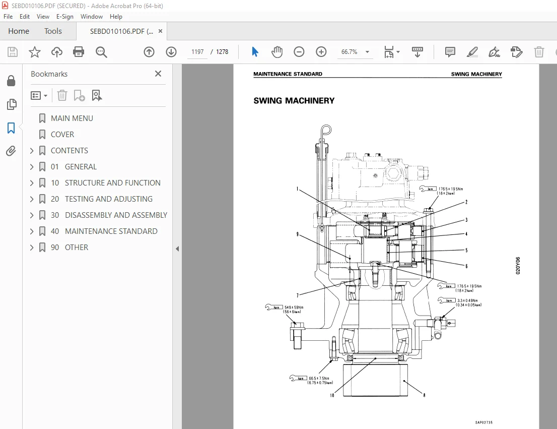
Swing Machinery 1197
Swing Circle 1199
Final Drive 1201
Track Frame – Recoil Spring 1203
Idler 1205
Carrier Roller 1207
Track Roller 1208
Track Shoe 1209
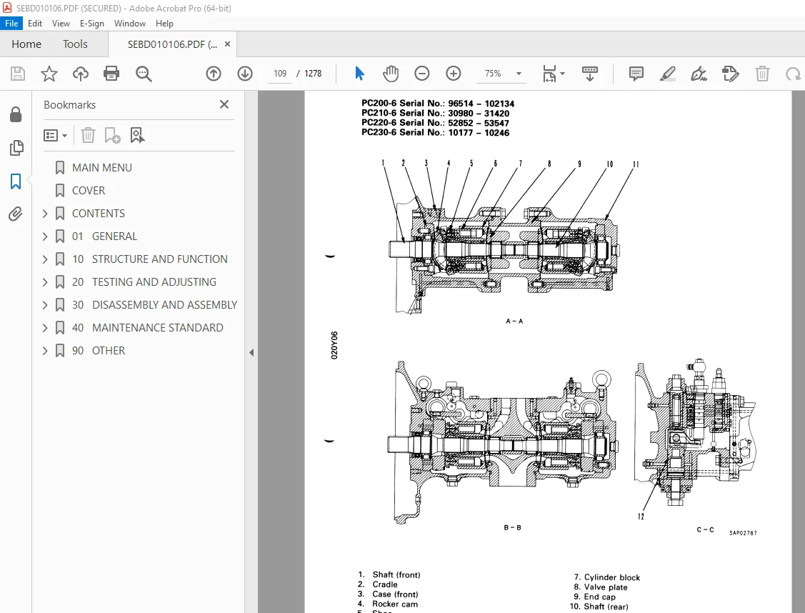
Hydraulic Pump 1215
Control Valve 1216
Safety-Suction Valve (for Service Valve) 1229
Self-Reducing Pressure Valve 1230
Swing Motor 1231
Travel Motor 1232
Work Equipment – Swing PPC Valve 1233
Work Equipment – Swing EPC Valve 1234
Tavel PPC Valve 1235
Service PPC Valve 1236
EPC Solenoid Valve 1237
Center Swivel Joint 1238
Boom Holding Valve 1240
Hydraulic Cylinder 1241
Work Equipment 1247
Dimension of Work Equipment 1253
90 OTHER 1260
Hydraulic Circuit Diagram (pg 90-3) 1261
PC200-6 STD Serial No : 96514 – 102228 1261
PC210-6 STD Serial No : 30980 – 31424 1261
PC220-6 STD Serial No : 52852 – 53561 1261
PC230-6 STD Serial No : 10177 – 10246 1261
Hydraulic Circuit Diagram (pg 90-5) 1262
PC200-6 STD Serial No : 102229 and UP 1262
PC210-6 STD Serial NO : 31425 and UP 1262
PC220-6 STD Serial No : 53562 and UP 1262
PC230-6 STD Serial NO : 10247 and UP 1262
Hydraulic Circuit Diagram (pg 90-7) 1263
PC200-6 HYPER GX Serial No : 96514 – 102228 1263
Hydraulic Circuit Diagram (pg 90-9) 1264
PC200-6 HYPER GX Serial No : 102229 and UP 1264
Hydraulic Circuit Diagram (pg 90-10-1) 1265
For Rotary Arm = PC200, 200LC-6 1265
Electrical Circuit Diagram [ 1/2 ] (pg 90-11) 1266
PC200-6 STD Serial No : 96514 – 102228 1266
PC210-6 STD Serial No : 30980 – 31424 1266
PC220-6 STD Serial No : 52852 – 53561 1266
PC230-6 STD Serial No : 10177 – 10246 1266
Electrical Circuit Diagram [ 2/2 ] (pg 90-13) 1267
PC200-6 STD Serial No : 96514 – 102228 1267
PC210-6 STD Serial No : 30980 – 31424 1267
PC220-6 STD Serial NO : 52852 – 53561 1267
PC230-6 STD Serial No : 10177 – 10246 1267
Electrical Circuit Diagram [1/2 ] (pg 90-15) 1268
PC200-6 STD Serial No : 102229 and UP 1268
PC210-6 STD Serial No : 31425 and UP 1268
PC220-6 STD Serial No : 53562 and UP 1268
PC230-6 STD Serial No : 10247 and UP 1268
Electrical Circuit Diagram [ 2/2 ] (pg 90-17) 1269
PC200-6 STD Serial No : 102229 and UP 1269
PC210-6 STD Serial No : 31425 and UP 1269
PC220-6 STD Serial No : 53562 and UP 1269
PC230-6 STD Serial No : 10247 and UP 1269
Electrical Circuit Diagram [ 1/3 ] (pg 90-19) 1270
PC200-6 HYPER GX Serial No : 94999 – 102228 1270
Electrical Circuit Diagram [ 2/3 ] (pg 90-21) 1271
PC200-6 HYPER GX Serial No : 94999 – 102228 1271
Electrical Circuit Diagram [ 3/3 ] (pg 90-23) 1272
PC200-6 HYPER GX Serial No : 94999 – 102228 1272
Electrical Circuit Diagram (pg 90-25) 1273
PC200-6 HYPER GX Serial No : 94999 – 102228 1273
Electrical Circuit Diagram [ 1/3 ] (pg 90-27) 1274
PC200-6 HYPER GX Serial No : 102229 and UP 1274
Electrical Circuit Diagram [ 2/3 ] (pg 90-29) 1275
PC200-6 HYPER GX Serial No : 102229 and UP 1275
Electrical Circuit Diagram [ 3/3 ] (pg 90-31) 1276
PC200-6 HYPER GX Serial No : 102229 and UP 1276
Electrical Circuit Diagram (pg 90-33) 1277
PC200-6 HYPER GX Serial No : 102229 and UP 1277
DESCRIPTION:
Komatsu PC200-6 PC200LC-6 PC210-6 PC210LC-6 PC220-6 PC220LC-6 PC230-6 PC230LC-6 Excavator Shop Manual SEBM010106 – PDF DOWNLOAD
PC200, 200LC-6 STD 96514 and up
PC200, 200LC-6 HYPER GX 96514 and up
PC220, 220LC-6 STD 52852 and up
GENERAL PRECAUTIONS :
Mistakes in operation are extremely dangerous. Read the OPERATION & MAINTENANCE MANUAL carefully BEFORE operating the machine.
PREPARATIONS FOR WORK:
S.V 28/12/24


