KOMATSU PC1250 -11E0 PC1250SP-11E0 HYDRAULIC EXCAVATOR SHOP MANUAL SEN06771-07 – PDF DOWNLOAD
$40.95
KOMATSU PC1250 -11E0 PC1250SP-11E0 HYDRAULIC EXCAVATOR SHOP MANUAL SEN06771-07 – PDF DOWNLOAD
Description
KOMATSU PC1250 -11E0 PC1250SP-11E0 HYDRAULIC EXCAVATOR SHOP MANUAL SEN06771-07 – PDF DOWNLOAD
FILE DETAILS:
KOMATSU PC1250 -11E0 PC1250SP-11E0 HYDRAULIC EXCAVATOR SHOP MANUAL SEN06771-07 – PDF DOWNLOAD
Language : English
Pages : 2956
Downloadable : Yes
File Type : PDF
IMAGES PREVIEW OF THE MANUAL:
TABLE OF CONTENTS:
KOMATSU PC1250 -11E0 PC1250SP-11E0 HYDRAULIC EXCAVATOR SHOP MANUAL SEN06771-07 – PDF DOWNLOAD
Index
00 Index and Foreword 00-1
Abbreviation List 00-20
Foreword, Safety, Basic Information 00-23
How to Read the Shop Manual 00-23
Safety Notice for Operation 00-25
Precautions to Prevent Fire 00-33
Procedures If Fire Occurs 00-35
Precautions When You Discard Waste Materials 00-36
Engine Technology to Conform Exhaust Gas Emission 00-37
Precautions When You Handle Hydraulic Equipment 00-38
Precautions When You Disconnect and Connect Pipings 00-41
Precautions When You Handle Electrical Equipment 00-47
Precautions When You Handle Fuel System Equipment 00-49
Precautions When You Handle Intake System Equipment 00-50
Practical Use of KOMTRAX 00-51
Disconnect and Connect Push-Pull Type Coupler 00-52
Precautions for Disconnection and Connection of Connectors 00-56
How to Disconnect and Connect Deutsch Connector 00-60
How to Disconnect and Connect Slide Lock Type Connector 00-61
How to Disconnect and Connect Connector with Lock to Pull 00-63
How to Disconnect and Connect Connector with Lock to Push 00-64
How to Disconnect and Connect Connector with Housing to Rotate 00-66
How to Read the Codes for Electric Cable 00-67
Explanation of Terms for Maintenance Standard 00-71
Standard Tightening Torque Table 00-74
Conversion Table 00-81
01 Specifications 01-1
Table of Contents 01-2
Specifications 01-3
Specification Drawing 01-3
Working Range Drawings 01-6
Specifications 01-9
Weight Table 01-19
Fuel, Coolant, Lubricants (For European Union) 01-25
10 Structure and Function 10-1
Table of Contents 10-2
NOx Control System 10-6
Function of NOx Control System 10-6
Boot-up System 10-9
Layout Drawing of Boot-up System 10-9
System Operating Lamp System 10-10
Battery Disconnect Switch 10-12
Engine System 10-13
Layout Drawing of Engine System 10-13
Engine Control System 10-16
Auto-Deceleration System 10-19
Automatic Low Idle System 10-21
Engine Automatic Warm-up System 10-23
Overheat Prevention System 10-25
Turbocharger Protection System 10-26
Automatic Idle Stop System 10-28
Component Parts of Engine System 10-31
Cooling System 10-51
Layout Drawing of Cooling System 10-51
Fan Speed Control System of Hydraulic Fan 10-53
Engine Output Control System of Hydraulic Fan 10-55
Index 00 Index and Foreword
00-2 PC1250-11E0, PC1250SP-11E0
Fan Reverse Rotation System of Hydraulic Fan 10-57
Component Parts of Cooling System 10-58
Control System 10-80
Layout Drawing of Control System 10-80
Machine Monitor System 10-82
KomVision System 10-83
KOMTRAX Plus System 10-88
Component Parts of Control System 10-93
Hydraulic System 10-146
Layout Drawing of Hydraulic System 10-146
OLSS 10-149
Engine and Pump Combined Control System 10-162
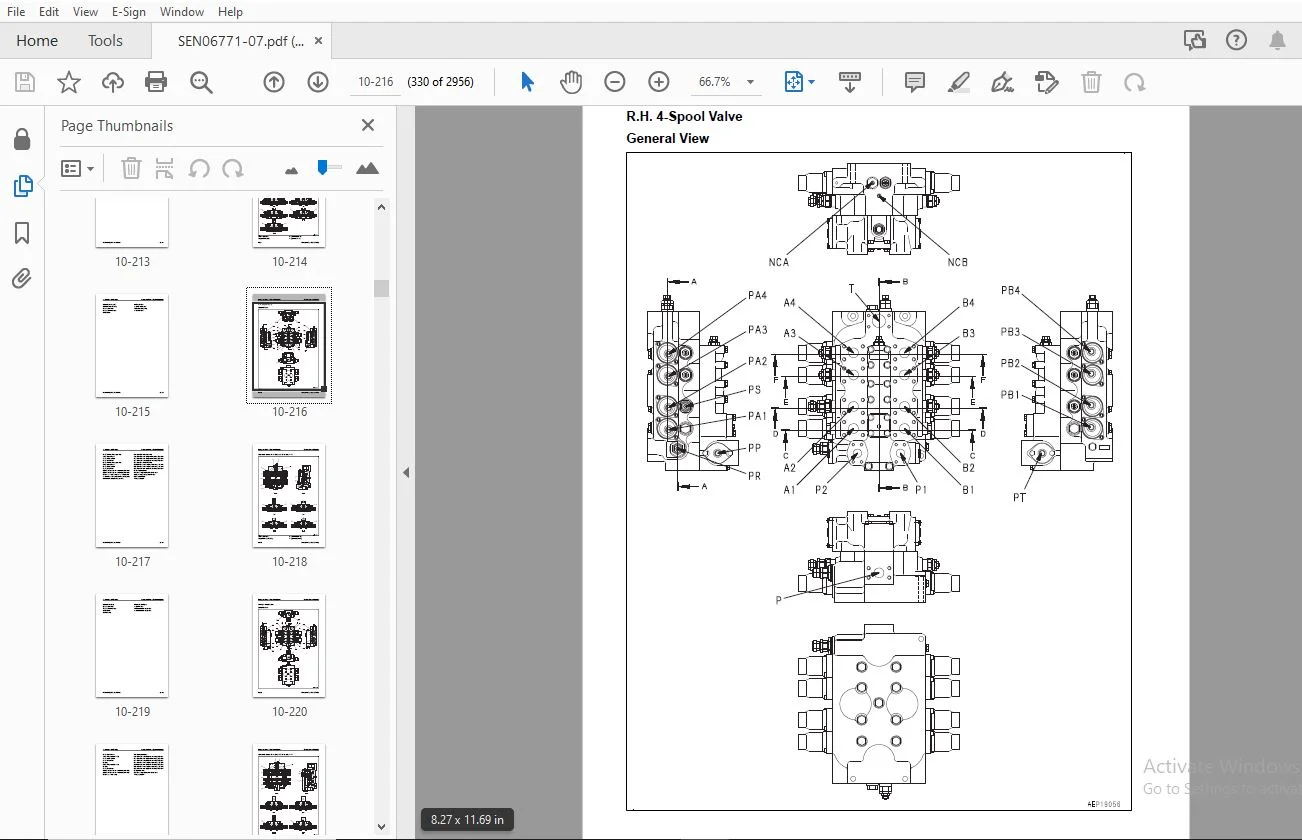
Component Parts of Hydraulic System 10-166
Work Equipment System 10-238
Layout Drawing of Work Equipment System 10-238
Machine Push-up System 10-244
Heavy Lift System 10-246
Boom Shockless Control System 10-249
PPC Lock System 10-251
Work Equipment and Travel Automatic Lock System 10-252
Component Parts of Work Equipment System 10-254
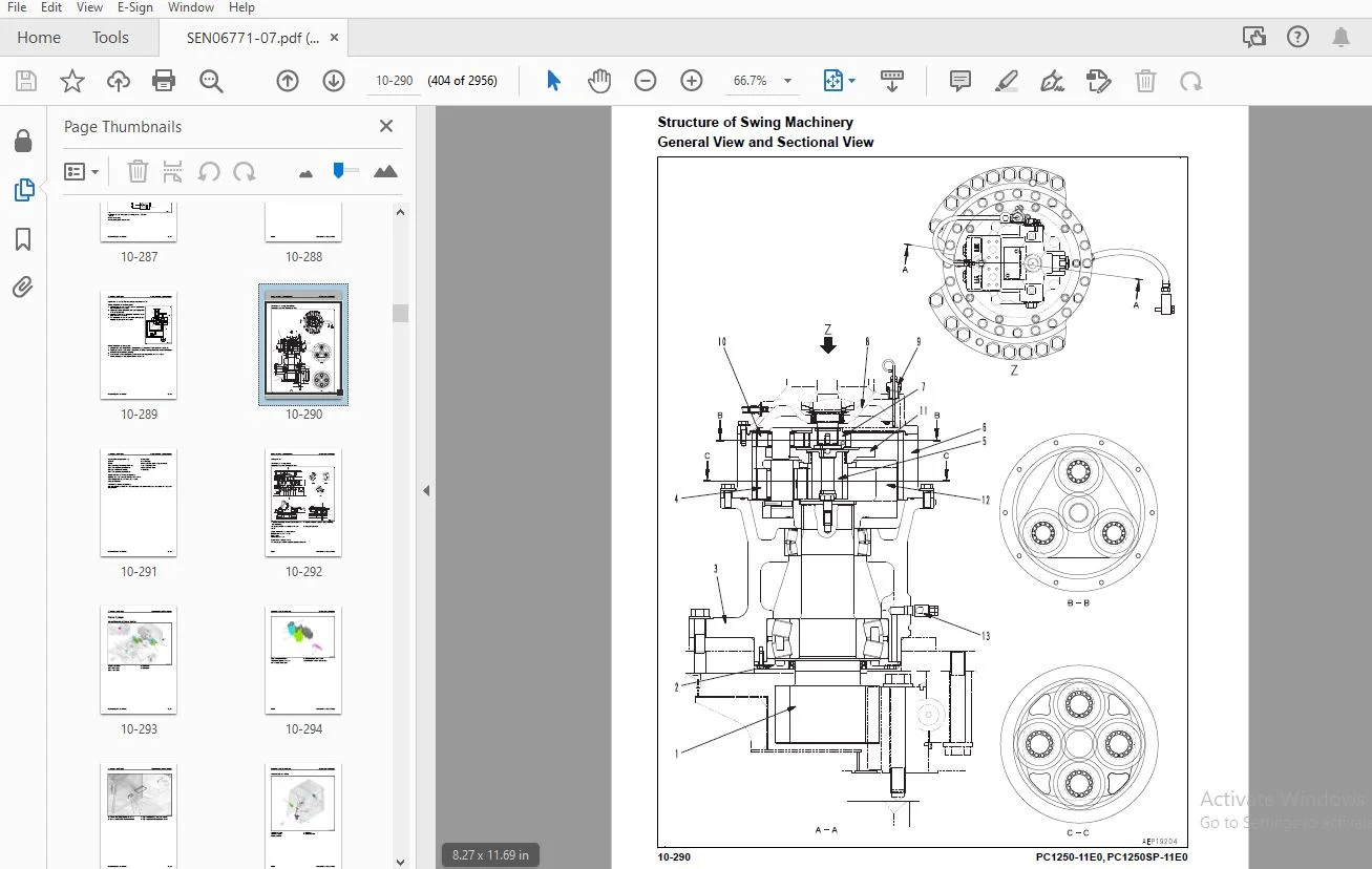
Swing System 10-267
Layout Drawing of Swing System 10-267
Swing Control System Diagram 10-270
Swing Priority System Diagram 10-274
Swing Compensation System Diagram 10-277
Component Parts of Swing System 10-278
Travel System 10-293
Layout Drawing of Travel System 10-293
System Diagram of Travel Control System 10-297
Component Parts of Travel System 10-300
Pneumatic System 10-319
Layout Drawing of Pneumatic System 10-319
Pneumatic System Diagram 10-320
Component Parts of Pneumatic System 10-321
Lifting System 10-326
Hydraulically Operated Stairway System 10-326
Component Parts of Lifting System 10-329
Undercarriage and Frame 10-332
Layout Drawing of Undercarriage 10-332
Work Equipment 10-334
Structure of Work Equipment 10-334
Function of Work Equipment 10-334
Work Equipment Clearance Adjustment Shim 10-335
Bucket Clearance Adjustment Shim 10-335
CAB Related Parts 10-336
CAB 10-336
CAB Mount 10-337
CAB Tipping Stopper 10-338
20 Standard Value Table 20-1
Table of Contents 20-2
Standard Value Table for Engine 20-3
Standard Value Table for Engine: PC1250-11E0 20-3
Standard Value Table for Engine: PC1250SP-11E0 20-8
Standard Value Table for Machine 20-13
Standard Value Table for Machine: PC1250-11E0 20-13
Standard Value Table for Machine: PC1250-11E0 (Loading Shovel Specification) 20-27
Standard Value Table for Machine: PC1250SP-11E0 20-42
00 Index and Foreword Index
PC1250-11E0, PC1250SP-11E0 00-3
Machine Posture and Procedures to Measure Performance 20-56
Machine Posture and Procedures to Measure Performance (Loading Shovel Specification) 20-60
30 Testing and Adjusting 30-1
Table of Contents 30-2
Precautions Before Work 30-6
Related Information on Testing and Adjusting 30-7
Tools for Testing and Adjusting 30-7
Sketch of Tools for Testing and Adjusting 30-14
Engine and Cooling System 30-15
Examine Engine Speed 30-15
Examine Boost Pressure 30-18
Examine Exhaust Gas Temperature 30-20
Examine Exhaust Gas Color 30-22
Examine Mass Air Flow and Temperature Sensor 30-26
Examine and Adjust Valve Clearance 30-28
Examine Compression Pressure 30-31
Examine Blowby Pressure 30-35
Examine Engine Oil Pressure 30-37
Examine EGR Valve and VGT Oil Pressure 30-39
Examine Fuel Pressure 30-40
Examine Fuel Return Rate and Leakage 30-42
Bleed Air from Fuel System 30-47
Examine Fuel Circuit for Leakage 30-49
Examine Supply Pump 30-51
Handle Cylinder Cut-out Mode Operation 30-54
Examine Alternator 30-55
Handle No-Injection Cranking Operation 30-56
Clean Fuel Doser 30-57
Write Injector Compensation Value to Engine Controller 30-60
Write Correction for Ash in Soot Accumulation to Engine Controller 30-66
Power Train 30-67
Examine Swing Circle Bearing Clearance 30-67
Undercarriage and Frame 30-69
Examine Sprocket Wear 30-69
Examine and Adjust Track Tension 30-70
Hydraulic System 30-72
Release Remained Pressure in Hydraulic Circuit 30-72
Examine and Adjust Oil Pressure in Work Equipment, Swing, and Travel Circuits 30-77
Examine and Adjust Oil Pressure in Control Circuit 30-91
Examine and Adjust Piston Pump Control Oil Pressure 30-93
Examine Servo Piston Stroke 30-102
Examine Outlet Pressure of Solenoid Valve 30-104
Examine PPC Valve Outlet Pressure 30-109
Examine Swing PPC Shuttle Valve Outlet Pressure 30-111
Adjust Play of Work Equipment and Swing PPC Valves 30-113
Examine Travel Deviation 30-114
Examine Cooling Fan Speed 30-115
Examine Aftercooler Fan Speed 30-116
Examine Oil Pressure in Fan Pump Circuit 30-117
Examine Aftercooler Fan Pump Circuit Oil Pressure 30-118
Examine Fan Pump EPC Electric Current 30-119
Examine Fan Pump EPC Solenoid Valve Outlet Pressure 30-120
Examine Parts Which Cause Hydraulic Drift of Work Equipment 30-121
Examine Oil Leakage 30-123
Bleed Air from Hydraulic System 30-128
CAB Related Parts 30-133
Examine CAB Tipping Stopper 30-133
How to Adjust Mirrors 30-134
Index 00 Index and Foreword
00-4 PC1250-11E0, PC1250SP-11E0
Electrical System 30-141
Set and Operate Machine Monitor 30-141
How to Start Up KOMTRAX Terminal 30-207
Default Setting of KOMTRAX Plus Controller 30-213
Default Setting of Wireless LAN Modem 30-216
Download Data from KOMTRAX Plus Controller 30-219
Adjust After Replacement of KOMTRAX Plus Controller 30-223
Adjust After Replacement of Wireless LAN Modem 30-226
Adjust KomVision Camera Angle 30-229
Adjust KomVision Related Function 30-232
Handle Voltage Circuit of Engine Controller 30-254
Handle Battery Disconnect Switch 30-255
Examine Diodes 30-256
Pm Clinic 30-257
Pm Clinic Service 30-257
Perform Quick Pm 30-288
40 Troubleshooting 40-1
Table of Contents 40-2
Precautions Before Work 40-13
Related Information to Troubleshooting 40-14
General Troubleshooting Points 40-14
Troubleshooting Points for Aftertreatment System 40-15
Table of Failure Codes that is Applied to Inducement 40-22
Sequence of Events in Troubleshooting 40-23
Checks Before Troubleshooting 40-25
Inspection Procedure Before Troubleshooting 40-27
Test in Accordance with Testing Procedure 40-29
Preparation for Troubleshooting of Electrical System 40-52
Procedure for Troubleshooting 40-58
Symptom and Troubleshooting Numbers 40-61
Information Shown in Troubleshooting Table 40-66
How to Diagnose Open Circuit of Hydraulic Pressure Sensor System Wiring Harness 40-68
Connector List and Layout 40-71
Connector List and Layout (Loading Shovel Specification) 40-87
Connector Contact Connection Table 40-104
T-Branch Box and T-Branch Adapter Table 40-144
Fuse Location Table 40-150
Precautions When You Clean and Replace KDPF (KCSF and KDOC) 40-153
Prepare of Short Socket Adapter (For Failure Codes [CA1883], [CB1883], [CA3135] and [CB3135])
40-157
Failure Code Table 40-159
Troubleshooting by Failure Code (Display of Code) 40-177
Failure Code [879AKA] 40-177
Failure Code [879AKB] 40-178
Failure Code [879BKA] 40-179
Failure Code [879BKB] 40-181
Failure Code [879CKA] 40-183
Failure Code [879CKB] 40-184
Failure Code [879DKZ] 40-185
Failure Code [879EMC] 40-187
Failure Code [879FMC] 40-188
Failure Code [879GKX] 40-189
Failure Code [8800ZG] 40-191
Failure Code [989L00] 40-192
Failure Code [989M00] 40-193
Failure Code [989N00] 40-194
Failure Code [A1U0N3] 40-195
Failure Code [A1U0N4] 40-197
00 Index and Foreword Index
PC1250-11E0, PC1250SP-11E0 00-5
Failure Code [AA10NX] 40-199
Failure Code [AB00KE] 40-201
Failure Code [AQ00N3] 40-203
Failure Code [AQ00N4] 40-204
Failure Code [AQ10N3] 40-205
Failure Code [AS00R2] 40-206
Failure Code [AS00R3] 40-207
Failure Code [AS00R4] 40-208
Failure Code [AS00R6] 40-209
Failure Code [B@BAZG] 40-210
Failure Code [B@BAZK] 40-211
Failure Code [B@BCNS] 40-213
Failure Code [B@BCZK] 40-214
Failure Code [B@CBNS] 40-216
Failure Code [B@HANS] 40-218
Failure Code [CA115] 40-219
Failure Code [CA122] 40-223
Failure Code [CA123] 40-225
Failure Code [CA131] 40-227
Failure Code [CA132] 40-229
Failure Code [CA135] 40-231
Failure Code [CA141] 40-233
Failure Code [CA144] 40-235
Failure Code [CA145] 40-237
Failure Code [CA153] 40-239
Failure Code [CA154] 40-242
Failure Code [CA187] 40-244
Failure Code [CA212] 40-246
Failure Code [CA213] 40-248
Failure Code [CA221] 40-250
Failure Code [CA222] 40-252
Failure Code [CA227] 40-254
Failure Code [CA234] 40-256
Failure Code [CA238] 40-257
Failure Code [CA239] 40-259
Failure Code [CA271] 40-261
Failure Code [CA272] 40-263
Failure Code [CA273] 40-264
Failure Code [CA274] 40-266
Failure Code [CA322] 40-267
Failure Code [CA323] 40-269
Failure Code [CA324] 40-271
Failure Code [CA325] 40-273
Failure Code [CA331] 40-275
Failure Code [CA332] 40-277
Failure Code [CA343] 40-279
Failure Code [CA351] 40-281
Failure Code [CA352] 40-283
Failure Code [CA356] 40-285
Failure Code [CA357] 40-287
Failure Code [CA386] 40-289
Failure Code [CA441] 40-291
Failure Code [CA442] 40-293
Failure Code [CA449] 40-295
Failure Code [CA451] 40-296
Failure Code [CA452] 40-298
Failure Code [CA515] 40-300
Failure Code [CA516] 40-301
Index 00 Index and Foreword
00-6 PC1250-11E0, PC1250SP-11E0
Failure Code [CA553] 40-302
Failure Code [CA555] 40-303
Failure Code [CA556] 40-305
Failure Code [CA559] 40-307
Failure Code [CA595] 40-312
Failure Code [CA687] 40-314
Failure Code [CA689] 40-316
Failure Code [CA691] 40-318
Failure Code [CA692] 40-320
Failure Code [CA697] 40-322
Failure Code [CA698] 40-323
Failure Code [CA731] 40-324
Failure Code [CA778] 40-328
Failure Code [CA1117] 40-330
Failure Code [CA1135] 40-332
Failure Code [CA1257] 40-335
Failure Code [CA1664] 40-336
Failure Code [CA1691] 40-338
Failure Code [CA1695] 40-341
Failure Code [CA1696] 40-343
Failure Code [CA1843] 40-345
Failure Code [CA1844] 40-347
Failure Code [CA1879] 40-349
Failure Code [CA1881] 40-351
Failure Code [CA1883] 40-353
Failure Code [CA1921] 40-356
Failure Code [CA1922] 40-358
Failure Code [CA1923] 40-362
Failure Code [CA1924] 40-364
Failure Code [CA1925] 40-366
Failure Code [CA1927] 40-368
Failure Code [CA1928] 40-370
Failure Code [CA1942] 40-372
Failure Code [CA1963] 40-374
Failure Code [CA1977] 40-378
Failure Code [CA1993] 40-380
Failure Code [CA2185] 40-382
Failure Code [CA2186] 40-383
Failure Code [CA2249] 40-385
Failure Code [CA2265] 40-390
Failure Code [CA2266] 40-392
Failure Code [CA2271] 40-394
Failure Code [CA2272] 40-396
Failure Code [CA2349] 40-398
Failure Code [CA2353] 40-400
Failure Code [CA2357] 40-402
Failure Code [CA2381] 40-405
Failure Code [CA2382] 40-407
Failure Code [CA2383] 40-409
Failure Code [CA2386] 40-411
Failure Code [CA2387] 40-413
Failure Code [CA2555] 40-418
Failure Code [CA2556] 40-420
Failure Code [CA2637] 40-422
Failure Code [CA2639] 40-425
Failure Code [CA2732] 40-427
Failure Code [CA2733] 40-429
Failure Code [CA2741] 40-431
00 Index and Foreword Index
PC1250-11E0, PC1250SP-11E0 00-7
Failure Code [CA2765] 40-432
Failure Code [CA2777] 40-433
Failure Code [CA2878] 40-435
Failure Code [CA2881] 40-438
Failure Code [CA3133] 40-441
Failure Code [CA3134] 40-443
Failure Code [CA3135] 40-445
Failure Code [CA3167] 40-448
Failure Code [CA3251] 40-451
Failure Code [CA3253] 40-453
Failure Code [CA3254] 40-457
Failure Code [CA3255] 40-460
Failure Code [CA3256] 40-463
Failure Code [CA3311] 40-465
Failure Code [CA3312] 40-467
Failure Code [CA3313] 40-469
Failure Code [CA3314] 40-470
Failure Code [CA3315] 40-471
Failure Code [CA3316] 40-474
Failure Code [CA3317] 40-475
Failure Code [CA3318] 40-476
Failure Code [CA3319] 40-479
Failure Code [CA3321] 40-480
Failure Code [CA3322] 40-481
Failure Code [CA3419] 40-484
Failure Code [CA3421] 40-486
Failure Code [CA4151] 40-488
Failure Code [CA4158] 40-491
Failure Code [CA4161] 40-492
Failure Code [CA4162] 40-494
Failure Code [CA4163] 40-496
Failure Code [CA4259] 40-498
Failure Code [CA4952] 40-500
Failure Code [CA5383] 40-502
Failure Code [CB115] 40-503
Failure Code [CB187] 40-506
Failure Code [CB227] 40-508
Failure Code [CB238] 40-509
Failure Code [CB239] 40-511
Failure Code [CB271] 40-513
Failure Code [CB272] 40-515
Failure Code [CB273] 40-516
Failure Code [CB274] 40-518
Failure Code [CB343] 40-519
Failure Code [CB352] 40-521
Failure Code [CB386] 40-523
Failure Code [CB441] 40-525
Failure Code [CB442] 40-527
Failure Code [CB689] 40-529
Failure Code [CB697] 40-531
Failure Code [CB698] 40-532
Failure Code [CB731] 40-533
Failure Code [CB778] 40-537
Failure Code [CB1117] 40-539
Failure Code [CB1257] 40-541
Failure Code [CB1664] 40-542
Failure Code [CB1691] 40-544
Failure Code [CB1695] 40-547
Index 00 Index and Foreword
00-8 PC1250-11E0, PC1250SP-11E0
Failure Code [CB1696] 40-549
Failure Code [CB1879] 40-551
Failure Code [CB1881] 40-553
Failure Code [CB1883] 40-555
Failure Code [CB1921] 40-558
Failure Code [CB1922] 40-560
Failure Code [CB1923] 40-564
Failure Code [CB1924] 40-566
Failure Code [CB1925] 40-568
Failure Code [CB1927] 40-570
Failure Code [CB1928] 40-572
Failure Code [CB1963] 40-574
Failure Code [CB1977] 40-578
Failure Code [CB1993] 40-580
Failure Code [CB2265] 40-582
Failure Code [CB2266] 40-584
Failure Code [CB2637] 40-586
Failure Code [CB2639] 40-589
Failure Code [CB2732] 40-591
Failure Code [CB2733] 40-593
Failure Code [CB2741] 40-595
Failure Code [CB2777] 40-597
Failure Code [CB2878] 40-599
Failure Code [CB2881] 40-602
Failure Code [CB3133] 40-605
Failure Code [CB3134] 40-607
Failure Code [CB3135] 40-609
Failure Code [CB3167] 40-612
Failure Code [CB3251] 40-615
Failure Code [CB3253] 40-617
Failure Code [CB3254] 40-622
Failure Code [CB3255] 40-625
Failure Code [CB3256] 40-628
Failure Code [CB3311] 40-630
Failure Code [CB3312] 40-632
Failure Code [CB3313] 40-634
Failure Code [CB3314] 40-635
Failure Code [CB3315] 40-636
Failure Code [CB3316] 40-639
Failure Code [CB3317] 40-640
Failure Code [CB3318] 40-641
Failure Code [CB3319] 40-644
Failure Code [CB3321] 40-645
Failure Code [CB3322] 40-646
Failure Code [CB4151] 40-649
Failure Code [CB4158] 40-652
Failure Code [CB4161] 40-653
Failure Code [CB4162] 40-655
Failure Code [CB4163] 40-657
Failure Code [CB4259] 40-659
Failure Code [CB4952] 40-661
Failure Code [CB5383] 40-663
Failure Code [D110KB] 40-664
Failure Code [D163KB] 40-666
Failure Code [D195KA] 40-668
Failure Code [D195KB] 40-670
Failure Code [D19JKZ] 40-672
Failure Code [D862KA] 40-674
00 Index and Foreword Index
PC1250-11E0, PC1250SP-11E0 00-9
Failure Code [D8AQKR] 40-676
Failure Code [DA20MC] 40-680
Failure Code [DA22KK] 40-681
Failure Code [DA25KP] 40-683
Failure Code [DA26KP] 40-685
Failure Code [DA29KQ] 40-687
Failure Code [DA2LKA] 40-689
Failure Code [DA2LKB] 40-691
Failure Code [DA2QKR] 40-693
Failure Code [DA2RKR] 40-698
Failure Code [DAF0KM] 40-703
Failure Code [DAF0MB] 40-704
Failure Code [DAF0MC] 40-705
Failure Code [DAF9KQ] 40-706
Failure Code [DAFGMC] 40-707
Failure Code [DAFLKA] 40-708
Failure Code [DAFLKB] 40-711
Failure Code [DAFQKR] 40-713
Failure Code [DAZ9KQ] 40-718
Failure Code [DAZQKR] 40-719
Failure Code [DB2QKR] 40-722
Failure Code [DB2RKR] 40-729
Failure Code [DBP0KM] 40-735
Failure Code [DBP0KT] 40-736
Failure Code [DBP5KB] 40-737
Failure Code [DBP5KY] 40-739
Failure Code [DBPQKR] 40-741
Failure Code [DBV0MC] 40-746
Failure Code [DBV1KK] 40-747
Failure Code [DBV5KB] 40-749
Failure Code [DBV6KB] 40-753
Failure Code [DBVLKA] 40-755
Failure Code [DBVLKB] 40-757
Failure Code [DBVQKR] 40-759
Failure Code [DBVRKR] 40-763
Failure Code [DBVVKR] 40-767
Failure Code [DBVWKR] 40-768
Failure Code [DDNRKA] 40-769
Failure Code [DDNRKY] 40-771
Failure Code [DDNS00] 40-773
Failure Code [DGE5KB] 40-775
Failure Code [DGH2KA] 40-776
Failure Code [DGH2KB] 40-778
Failure Code [DGT3KB] 40-780
Failure Code [DGT4KA] 40-782
Failure Code [DGT4KB] 40-784
Failure Code [DHA4KA] 40-786
Failure Code [DHAAMA] 40-788
Failure Code [DHABMA] 40-789
Failure Code [DHACMA] 40-790
Failure Code [DHADMA] 40-791
Failure Code [DHPAMA] 40-792
Failure Code [DHPAZL] 40-794
Failure Code [DHPBMA] 40-795
Failure Code [DHPBZL] 40-797
Failure Code [DHPGMA] 40-798
Failure Code [DHPGZL] 40-800
Failure Code [DHPSMA] 40-801
Index 00 Index and Foreword
00-10 PC1250-11E0, PC1250SP-11E0
Failure Code [DHPTKA] 40-803
Failure Code [DHPTKB] 40-805
Failure Code [DHS3MA] 40-807
Failure Code [DHS4MA] 40-810
Failure Code [DHS8MA] 40-813
Failure Code [DHS9MA] 40-816
Failure Code [DHSAMA] 40-819
Failure Code [DHSBMA] 40-822
Failure Code [DHSCMA] 40-825
Failure Code [DHSDMA] 40-828
Failure Code [DHSFMA] 40-831
Failure Code [DHSGMA] 40-834
Failure Code [DHSHMA] 40-837
Failure Code [DHSJMA] 40-840
Failure Code [DKR2KA] 40-843
Failure Code [DKR2KB] 40-845
Failure Code [DKR2NX] 40-847
Failure Code [DKR3KA] 40-849
Failure Code [DKR3KB] 40-851
Failure Code [DKR3NX] 40-853
Failure Code [DKULKA] 40-855
Failure Code [DKULKB] 40-857
Failure Code [DKULKY] 40-859
Failure Code [DLM3KA] 40-861
Failure Code [DLM3KB] 40-863
Failure Code [DLM3MB] 40-865
Failure Code [DR10KA] 40-866
Failure Code [DR12KA] 40-869
Failure Code [DR20KA] 40-871
Failure Code [DR21KX] 40-873
Failure Code [DR30KA] 40-875
Failure Code [DR31KX] 40-877
Failure Code [DR40KA] 40-879
Failure Code [DUMBKA] 40-881
Failure Code [DUMBKB] 40-884
Failure Code [DV20KB] 40-886
Failure Code [DW41KA] 40-888
Failure Code [DW41KB] 40-890
Failure Code [DW41KY] 40-892
Failure Code [DW43KA] 40-893
Failure Code [DW43KB] 40-895
Failure Code [DW43KY] 40-896
Failure Code [DW45KA] 40-897
Failure Code [DW45KB] 40-900
Failure Code [DW45KY] 40-903
Failure Code [DW48KA] 40-905
Failure Code [DW48KB] 40-907
Failure Code [DW48KY] 40-909
Failure Code [DW4CKY] 40-910
Failure Code [DW7BKA] 40-912
Failure Code [DW7BKB] 40-914
Failure Code [DW7BKY] 40-916
Failure Code [DW91KA] 40-917
Failure Code [DW91KB] 40-919
Failure Code [DW91KY] 40-920
Failure Code [DWA5KA] 40-921
Failure Code [DWA5KB] 40-923
Failure Code [DWA5KY] 40-925
00 Index and Foreword Index
PC1250-11E0, PC1250SP-11E0 00-11
Failure Code [DWK0KA] 40-927
Failure Code [DWK0KB] 40-929
Failure Code [DWK0KY] 40-931
Failure Code [DWK2KA] 40-932
Failure Code [DWK2KB] 40-934
Failure Code [DWK2KY] 40-936
Failure Code [DWK8KA] 40-937
Failure Code [DWK8KB] 40-939
Failure Code [DWK8KY] 40-941
Failure Code [DX16KA] 40-942
Failure Code [DX16KB] 40-944
Failure Code [DX51KA] 40-946
Failure Code [DX51KB] 40-947
Failure Code [DX51KY] 40-949
Failure Code [DX52KA] 40-950
Failure Code [DX52KB] 40-951
Failure Code [DX52KY] 40-953
Failure Code [DXA0KA] 40-954
Failure Code [DXA0KB] 40-956
Failure Code [DXAXKA] 40-958
Failure Code [DXAXKB] 40-960
Failure Code [DY20KA] 40-962
Failure Code [DY20KA] 40-964
Failure Code [DY20MA] 40-967
Failure Code [DY20MA] 40-969
Failure Code [DY2CKB] 40-972
Failure Code [DY2DKB] 40-974
Failure Code [DY2DKB] 40-976
Failure Code [DY2EKB] 40-979
Failure Code [DY2EKB] 40-981
Failure Code [DY2FMA] 40-984
Failure Code [DY2GKM] 40-986
Failure Code [F@BYNR] 40-988
Failure Code [F@BYNS] 40-989
Failure Code [J100KA] 40-990
Failure Code [J100KB] 40-992
Failure Code [J100L6] 40-994
Failure Code [J190KA] 40-995
Failure Code [J190KB] 40-997
Failure Code [J190L6] 40-999
Failure Code [LA10ZL] 40-1000
Troubleshooting of Electrical System (E-Mode) 40-1001
E-1 Engine Does Not Start (Engine Does Not Crank) 40-1001
E-2 Manual Preheating System Does Not Operate 40-1008
E-3 Automatic Preheating System Does Not Operate 40-1011
E-4 While Preheating is in Operation, Preheating Monitor Does Not Come On 40-1013
E-5 When Starting Switch is Turned to ON Position, Machine Monitor Shows Nothing 40-1015
E-6 While Starting Switch is Turned to ON Position (with Engine Stopped), Engine Oil Level Monitor
Comes On in Yellow 40-1018
E-7 While Starting Switch is Turned to ON Position (with Engine Stopped), Radiator Coolant Level
Monitor Comes On in Yellow 40-1019
E-8 Engine Coolant Temperature Monitor Comes On While Engine is in Operation 40-1020
E-9 Hydraulic Oil Temperature Monitor Comes On in White While Engine Runs 40-1021
E-10 Air Cleaner Clogging Monitor Comes On in Yellow While Engine Runs 40-1022
E-11 Charge Level Monitor Comes On in Red While Engine is in Operation 40-1023
E-12 Fuel Level Monitor Comes On in Red While Engine Runs 40-1024
E-13 Engine Coolant Temperature Monitor Comes On in Red While Engine is in Operation 40-1025
E-14 Engine Oil Pressure Monitor Comes on in Red While Engine is in Operation 40-1026
Index 00 Index and Foreword
00-12 PC1250-11E0, PC1250SP-11E0
E-15 Hydraulic Oil Temperature Monitor Comes on in Red While Engine is in Operation 40-1027
E-16 Fuel Gauge Display Does Not Move from Minimum or Maximum 40-1028
E-17 Display of Fuel Gauge is Different from Actual Fuel Level 40-1030
E-18 Coolant Temperature Gauge Display Does Not Move from Minimum or Maximum 40-1031
E-19 Display of Coolant Temperature Gauge is Different from Actual Coolant Temperature 40-1032
E-20 Hydraulic Oil Temperature Gauge Display Does Not Move from Minimum or Maximum 40-1033
E-21 Display of Hydraulic Oil Temperature Gauge is Different from Actual Oil Temperature 40-1035
E-22 Some Areas of Machine Monitor Screen are Not Shown 40-1036
E-23 Function Switch Does Not Operate 40-1037
E-24 Automatic Warm-up System Does Not Work (in Cold Weather) 40-1038
E-25 When Auto-Decelerator Switch is Operated, Auto-Decelerator Monitor Does Not Come On or
Does Not Go Out 40-1039
E-26 Auto-Decelerator is Not Operated or Canceled with Lever 40-1040
E-27 When Working Mode Switch is Operated, Working Mode Selection Screen is Not Shown 40-1041
E-28 When Working Mode is Changed, Setting of Engine and Hydraulic Pump is Not Changed 40-1042
E-29 When Travel Speed Switch is Operated, Travel Speed Monitor Does Not Change 40-1043
E-30 When Travel Speed Selection is Changed, Actual Travel Speed Does Not Change 40-1044
E-31 Alarm Buzzer Cannot be Canceled 40-1045
E-32 Service Meter is Not Shown, While Starting Switch is in OFF Position 40-1046
E-33 Service Mode Cannot be Selected 40-1047
E-34 All of Work Equipment, Swing, and Travel Mechanism Do Not Move 40-1048
E-35 All Work Equipment, Swing and Travel Do Not Lock 40-1051
E-36 When Swing Brake Cancel Switch is Set to Cancel Position, Machine Cannot Swing 40-1053
E-37 When Swing Brake Cancel Switch is Set to Normal Position, Swing Holding Brake Does Not Operate
40-1056
E-38 Alarm Does Not Sound During Travel 40-1058
E-39 Travel Alarm Does Not Stop When Machine Stops 40-1060
E-40 Horn Does Not Sound 40-1061
E-41 Horn Does Not Stop 40-1064
E-42 When Wiper Switch is Operated, Wiper Monitor Does Not Come On or Go Out 40-1066
E-43 Wiper Does Not Operate When Wiper Switch is Operated (Single Wiper Specification) 40-1067
E-44 Wiper Does Not Operate When Wiper Switch is Operated (Double Wiper Specification) 40-1069
E-45 Fuel Feed Pump Does Not Operate or Stop Automatically 40-1071
E-46 Window Washer Does Not Operate When Window Washer Switch is Operated 40-1074
E-47 “Boom RAISE” is Not Shown Correctly with Monitoring Function 40-1075
E-48 “Boom LOWER” is Not Shown Correctly with Monitoring Function 40-1076
E-49 “Arm OUT” is Not Shown Correctly with Monitoring Function 40-1077
E-50 “Arm IN” is Not Shown Correctly with Monitoring Function 40-1078
E-51 “Bucket DUMP” is Not Shown Correctly with Monitoring Function 40-1079
E-52 “Bucket CURL” is Not Shown Correctly with Monitoring Function 40-1080
E-53 “Swing” is Not Shown Correctly with Monitoring Function 40-1081
E-54 “Travel” is Not Shown Correctly with Monitoring Function 40-1082
E-55 KOMTRAX System Does Not Operate Correctly 40-1083
E-56 Machine Push-Up Function Cannot be Canceled 40-1084
E-57 Machine Push-Up Function Does Not Operate 40-1086
E-58 Step Light Does Not Come On 40-1087
E-59 Step Light Does Not Go Out 40-1090
E-60 Boom Shockless Function Cannot be Canceled 40-1092
E-61 Boom Shockless Function Does Not Work 40-1094
E-62 Bottom Dump Cannot be Operated 40-1095
Troubleshooting for Hydraulic and Mechanical Systems (H Mode) 40-1098
H-1 All Work Equipment, Travel, and Swing Speed or Power is Low 40-1098
H-2 Engine Speed Drops Significantly or Engine Stalls 40-1100
H-3 All Work Equipment, Swing and Travel Do Not Work 40-1101
H-4 Unusual Noise is Heard from Around Work Equipment Pump 40-1103
H-5 Boom Speed or Power is Low in Normal Mode 40-1104
H-6 Boom RAISE Speed or Power is Low in Heavy Lift Mode 40-1105
H-7 Boom LOWER Speed or Power is Low in Machine Push Up Mode 40-1106
00 Index and Foreword Index
PC1250-11E0, PC1250SP-11E0 00-13
H-8 Arm Speed or Power is Low 40-1107
H-9 Bucket Speed or Power is Low 40-1108
H-10 Boom Does Not Operate 40-1109
H-11 Arm Does Not Operate 40-1110
H-12 Bucket Does Not Operate 40-1111
H-13 Hydraulic Drift of Boom is Large 40-1112
H-14 Hydraulic Drift of Arm is Large 40-1113
H-15 Hydraulic Drift of Bucket is Large 40-1114
H-16 Time Lag of Boom is Large 40-1115
H-17 Time Lag of Arm is Large 40-1116
H-18 Time Lag of Bucket is Large 40-1117
H-19 Boom Shockless Function Does Not Work or Cannot be Released 40-1118
H-20 Machine Accidentally Turns to One Side When Machine Travels (It Turns in the Same Direction
When Traveling Forward and Reverse) 40-1119
H-21 Machine Accidentally Turns to One Side When Machine Travels (It Turns in the Different Directions
When Traveling Forward and Reverse) 40-1121
H-22 Travel Deviation is Large at Start of Travel Only When Travel Lever is Fully Moved 40-1122
H-23 Regardless of the Stroke of the Travel Lever, Travel Deviation is Large at Start of Traveling40-1123
H-24 Travel Deviation is Large at Mixed Operation 40-1124
H-25 Travel Speed or Power is Low 40-1125
H-26 Only the One Side Track Can Operate (Machine Does Not Travel FORWARD or REVERSE)
40-1126
H-27 Only the One Side Track Can Operate (in Either Forward or Reverse Direction) 40-1127
H-28 Travel Speed Does Not Change, or Travel Speed is Too Slow or Fast 40-1128
H-29 Upper Structure Does Not Swing to Right and Left 40-1129
H-30 Upper Structure Swings Only to Right or Left 40-1130
H-31 Swing Acceleration or Swing Speed is Low in Lateral Directions (Right and Left) 40-1131
H-32 Swing Acceleration Performance is Unsatisfactory or Swing Speed is Slow in Only One Direction
40-1132
H-33 In Mixed Operation of Work Equipment, Swing Speed or Power is Low 40-1133
H-34 Swing Acceleration or Swing Speed is Low During Mixed Operation with Boom in Swing Priority
Mode 40-1134
H-35 Upper Structure Overruns Too Much When It Stops Swing Operation in Lateral Directions of Right
and Left 40-1135
H-36 Upper Structure Speed is High When It Stops Swing Operation (on One Side) 40-1136
H-37 Shock is Large When Upper Structure Stops Swing Operation (Right and Left) 40-1137
H-38 Shock is Large When Upper Structure Stops Swing Operation (in Only Right of Left Direction)
40-1138
H-39 Large Unusual Noise is Heard When Upper Structure Stops Swing Operation (in Right and Left
Directions) 40-1139
H-40 Large Unusual Noise is Heard When Upper Structure Stops Swing Operation in Only One Direction
40-1140
H-41 Swing Drift on a Slope is Large 40-1141
H-42 Fan Rotation is Abnormal (Such as Excessive Noise or Vibration of Fan, or Overheating) 40-1142
H-43 Bottom Dump Cannot be Moved 40-1143
Troubleshooting of Engine (S-Mode) 40-1144
Information Shown in Troubleshooting Table (S-Mode) 40-1144
S-1 Engine Does Not Crank When Starting Switch is Turned to Start Position 40-1145
S-2 Engine Cranks but No Exhaust Smoke Comes Out 40-1146
S-3 Fuel is Injected but Engine Does Not Start (Misfiring: Engine Cranks but Does Not Start) 40-1147
S-4 Engine Startability is Unsatisfactory 40-1148
S-5 Engine Does Not Pick Up Smoothly 40-1150
S-6 Engine Stops During Operation 40-1152
S-7 Engine Runs Rough or is Not Stable 40-1154
S-8 Engine Lacks Power 40-1155
S-9 KDPF Becomes Clogged in a Short Time 40-1157
S-10 Engine Oil Consumption is Excessive 40-1159
S-11 Oil Becomes Dirty Quickly 40-1160
Index 00 Index and Foreword
00-14 PC1250-11E0, PC1250SP-11E0
S-12 Fuel Consumption is Excessive 40-1161
S-13 Oil is in Coolant (or Coolant Spurts Back or Coolant 40-1162
S-14 Oil Pressure Drops 40-1163
S-15 Fuel Mixes Into Engine Oil 40-1165
S-16 Water Mixes Into Engine Oil (Milky) 40-1166
S-17 Coolant Temperature Increases Too High (Overheating) 40-1167
S-18 Unusual Noise is Heard 40-1169
S-19 Vibration is Excessive 40-1170
S-20 Air Cannot be Bled from Fuel Circuit 40-1171
S-21 Active Regeneration is Done Frequently 40-1172
S-22 Active Regeneration Continues Long 40-1173
S-23 White Smoke is Exhausted During Active Regeneration 40-1174
50 Disassembly and Assembly 50-1
Table of Contents 50-2
Precautions Before Work 50-7
Related Information on Disassembly and Assembly 50-8
How to Read This Manual 50-8
Coating Materials List 50-10
Special Tool List 50-15
Sketches of Special Tools 50-34
Engine and Cooling System 50-41
Remove and Install Supply Pump Assembly 50-41
Remove and Install Injector Assembly 50-67
Remove and Install Fuel Doser Assembly 50-91
Remove and Install Cylinder Head Assembly 50-97
Remove and Install EGR Valve Assembly 50-188
Remove and Install EGR Cooler Assembly 50-196
Remove and Install Starter Assembly 50-211
Remove and Install Alternator Belt 50-213
Remove and Install Radiator Assembly 50-216
Remove and Install Hydraulic Oil Cooler Assembly 50-225
Remove and Install Aftercooler Assembly 50-236
Remove and Install Cooling Fan Motor Assembly 50-248
Remove and Install Engine, PTO, and Hydraulic Pump Assembly 50-273
Remove and Install Engine Front Oil Seal 50-305
Remove and Install Engine Rear Oil Seal 50-312
Remove and Install Fuel Cooler Assembly 50-317
Remove and Install Engine Hood Assembly 50-320
Remove and Install Fuel Tank Assembly 50-333
Remove and Install KDPF Assembly 50-343
Disassemble and Assemble KDPF Assembly 50-356
Remove and Install Bellows Pipe Assembly 50-370
Remove and Install KCCV Assembly 50-378
Remove and Install Air Cleaner Assembly 50-382
Remove and Install Air Conditioner Compressor Assembly 50-384
Remove and Install Air Conditioner Condenser Assembly 50-387
Power Train 50-391
Disassemble and Assemble PTO Assembly 50-391
Remove and Install PTO Assembly 50-397
Remove and Install Travel Motor and Final Drive Assembly 50-402
Disassemble and Assemble Final Drive Assembly 50-404
Remove and Install Swing Motor and Swing Machinery Assembly 50-417
Disassemble and Assemble Swing Machinery Assembly 50-422
Remove and Install Swing Circle Assembly 50-432
Undercarriage and Frame 50-434
Remove and Install Idler Assembly 50-434
Disassemble and Assemble Recoil Spring Assembly 50-436
Remove and Install Track Roller Assembly 50-438
00 Index and Foreword Index
PC1250-11E0, PC1250SP-11E0 00-15
Remove and Install Carrier Roller Assembly 50-441
Disassemble and Assemble One Track Link Assembly in Field 50-443
Separate and Connect Track Assembly 50-449
Disassemble and Assemble Idler Assembly 50-452
Disassemble and Assemble Idler Adjustment Cylinder Assembly 50-457
Disassemble and Assemble Track Roller Assembly 50-459
Disassemble and Assemble Carrier Roller Assembly 50-463
Remove and Install Revolving Frame Assembly 50-466
Remove and Install Counterweight Assembly 50-469
Hydraulic System 50-473
Remove and Install Center Swivel Joint Assembly 50-473
Disassemble and Assemble Center Swivel Joint Assembly 50-476
Remove and Install Hydraulic Tank Assembly 50-479
Remove and Install Hydraulic Pump Assembly 50-488
Remove and Install Control Valve Assembly 50-511
Remove and Install Swing Motor Assembly 50-523
Disassemble and Assemble Work Equipment PPC Valve Assembly 50-526
Disassemble and Assemble Travel PPC Valve Assembly 50-529
Disassemble and Assemble Grease Gun Assembly 50-532
Work Equipment 50-533
Remove and Install Bucket Cylinder Assembly 50-533
Remove and Install Bucket Cylinder Assembly (Loading Shovel Specification) 50-536
Remove and Install Arm Cylinder Assembly 50-539
Remove and Install Arm Cylinder Assembly (Loading Shovel Specification) 50-543
Remove and Install Boom Cylinder Assembly 50-547
Remove and Install Boom Cylinder Assembly (Loading Shovel Specification) 50-550
Remove and Install Bucket Assembly 50-554
Remove and Install Bucket Assembly (Loading Shovel Specification) 50-558
Remove and Install Arm Assembly 50-561
Remove and Install Arm Assembly (Loading Shovel Specification) 50-564
Remove and Install Boom Assembly 50-567
Remove and Install Boom Assembly (Loading Shovel Specification) 50-571
Disassemble and Assemble Work Equipment Cylinder Assembly 50-575
Disassemble and Assemble Bottom Dump Cylinder Assembly (Loading Shovel Specification) 50-583
CAB Related Parts 50-594
Remove and Install Top Guard Assembly 50-594
Remove and Install Operator Cab Assembly 50-598
Remove and Install Operator Cab Glass (Adhered Glass) 50-617
Remove and Install Front Window Assembly 50-629
Remove and Install Floor Frame Assembly 50-638
Remove and Install Air Conditioner Unit Assembly 50-651
Remove and Install Operator Seat 50-663
How to Remove and Install Seat Belt 50-668
Remove and Install Front Wiper Assembly 50-670
Electrical System 50-684
Remove and Install Engine Controller Assembly 50-684
Remove and Install Pump Controller Assembly 50-689
Remove and Install KomVision Controller Assembly 50-694
Remove and Install Machine Monitor Assembly 50-696
Remove and Install Mass Air Flow and Temperature Sensor 50-702
Remove and Install KCCV Crankcase Pressure Sensor 50-705
Remove and Install KomVision Camera 50-708
Remove and Install KOMTRAX Terminal Assembly 50-711
Remove And Install KOMTRAX Plus Controller Assembly 50-715
Remove and Install Wireless LAN Unit Assembly 50-717
60 Maintenance Standard 60-1
Table of Contents 60-2
Engine and Cooling System 60-3
Index 00 Index and Foreword
00-16 PC1250-11E0, PC1250SP-11E0
Maintenance Standard for Engine Mount 60-3
Maintenance Standard for PTO 60-5
Maintenance Standard for Cooling System 60-6
Maintenance Standard for Cooling Fan Pump 60-8
Maintenance Standard for Cooling Fan Motor 60-11
Power Train 60-13
Maintenance Standard for Swing Circle 60-13
Maintenance Standard for Swing Machinery 60-14
Maintenance Standard for Final Drive 60-16
Maintenance Standard for Sprocket 60-18
Maintenance Standard for Sprocket Tooth Profile Full-Scale Drawing 60-19
Undercarriage and Frame 60-20
Maintenance Standard for Track Frame and Idler Cushion 60-20
Maintenance Standard for Idler 60-22
Maintenance Standard for Track Roller 60-24
Maintenance Standard for Carrier Roller 60-25
Maintenance Standard for Track Shoes 60-26
Maintenance Standard for Double Shoes 60-29
Hydraulic System 60-30
Maintenance Standard for Main Pump 60-30
Maintenance Standard for Swing Motor 60-34
Maintenance Standard for Control Valve 60-37
Maintenance Standard for Variable Back Pressure Valve 60-49
Maintenance Standard for Work Equipment and Swing PPC Valve 60-50
Maintenance Standard for Travel PPC Valve 60-53
Maintenance Standard for Solenoid Valve 60-55
Maintenance Standard for Center Swivel Joint 60-56
Work Equipment 60-57
Maintenance Standard for Work Equipment Linkage 60-57
Maintenance Standard for Work Equipment Linkage (Loading Shovel Specification) 60-64
Maintenance Standard for Boom Cylinder 60-71
Maintenance Standard for Boom Cylinder (Loading Shovel Specification) 60-72
Maintenance Standard for Arm Cylinder 60-73
Maintenance Standard for Arm Cylinder (Loading Shovel Specification) 60-74
Maintenance Standard for Bucket Cylinder 60-75
Maintenance Standard for Bucket Cylinder (Loading Shovel Specification) 60-76
Maintenance Standard for Bottom Dump Cylinder (Loading Shovel Specification) 60-77
80 Others 80-1
Table of Contents 80-2
Precautions Before Work 80-4
Air Conditioner System 80-5
Precautions for Refrigerant 80-5
Air Conditioner Component 80-6
Specifications of Air Conditioner 80-8
Structure and Function of Refrigeration Cycle 80-9
Outline of Refrigeration Cycle 80-10
Component Parts of Air Conditioner System 80-12
Air Conditioner Unit 80-12
Component Parts of Air Conditioner Unit 80-16
Air Conditioner Controller 80-20
Compressor 80-21
Condenser 80-22
Receiver Drier 80-23
Air Conditioner Related Sensors 80-24
Explanation of Procedure for Test of and Troubleshooting of Air Conditioner 80-26
Circuit Diagram and Configuration of Connector Pins of Air Conditioner 80-28
System Diagram of Air Conditioner 80-30
Input and Output Signals of Air Conditioner Controller 80-31
00 Index and Foreword Index
PC1250-11E0, PC1250SP-11E0 00-17
Locations of Air Conditioner Parts and Layout of Connectors 80-33
Examine Air Leakage (Duct) 80-37
How to Examine Air Leakage (Duct) 80-37
Examine Air Conditioner with Self-Diagnosis Function 80-39
Open the Electrical System Abnormality Record Screen in Service Mode of Machine Monitor 80-40
Examine Vent (Mode) Changeover 80-41
How to Examine Vent (Mode) Changeover 80-41
Examine Fresh/Recirc Air Changeover 80-43
How to Examine Fresh/Recirc Air Changeover 80-43
Examine Sunlight Sensor 80-44
How to Examine Sunlight Sensor 80-44
Examine Refrigerant (Dual) Pressure Switch 80-45
How to Examine Refrigerant (Dual) Pressure Switch 80-45
Examine Relay 80-46
How to Examine Relay 80-46
Air Conditioner Troubleshooting Chart 1 80-47
Air Conditioner Troubleshooting Chart 2 80-48
Information Shown in Troubleshooting Table 80-51
Failure Code [879AKA] 80-52
Failure Code [879AKB] 80-53
Failure Code [879BKA] 80-54
Failure Code [879BKB] 80-56
Failure Code [879CKA] 80-58
Failure Code [879CKB] 80-59
Failure Code [879DKZ] 80-60
Failure Code [879EMC] 80-62
Failure Code [879FMC] 80-63
Failure Code [879GKX] 80-64
A-1 Troubleshooting for Power Supply System (Air Conditioner Does Not Operate) 80-66
A-2 Troubleshooting for Compressor and Refrigerant System (Air is Not Cooled) 80-68
A-3 Troubleshooting for Blower Motor System (No Air Comes Out or Air Flow is Abnormal) 80-71
A-4 Troubleshooting for Fresh/Recirc Air Changeover 80-73
Troubleshooting by Gauge Pressure 80-75
Connect Service Tool 80-78
How to Connect Service Tool 80-78
Precautions for Disconnection and Connection of Air Conditioner Piping 80-80
Handle Compressor Oil 80-82
90 Circuit Diagrams 90-1
Table of Contents 90-2
Hydraulic Circuit Diagram 90-3
Symbols Used in Hydraulic Circuit Diagram 90-3
Hydraulic Circuit Diagram (1/3) 90-7
Hydraulic Circuit Diagram (2/3) 90-9
Hydraulic Circuit Diagram (3/3) 90-11
Electrical Circuit Diagram 90-13
Symbols Used in Electric Circuit Diagram 90-13
Electrical Circuit Diagram (1/14) 90-17
Electrical Circuit Diagram (2/14) 90-19
Electrical Circuit Diagram (3/14) 90-21
Electrical Circuit Diagram (4/14) 90-23
Electrical Circuit Diagram (5/14) 90-25
Electrical Circuit Diagram (6/14) 90-27
Electrical Circuit Diagram (7/14) 90-29
Electrical Circuit Diagram (8/14) 90-31
Electrical Circuit Diagram (9/14) 90-33
Electrical Circuit Diagram (10/14) 90-35
Electrical Circuit Diagram (11/14) 90-37
Electrical Circuit Diagram (12/14) 90-39
Electrical Circuit Diagram (13/14) 90-41
Electrical Circuit Diagram (14/14) 90-43
Electrical Circuit Diagram (1/14) (Loading Shovel Specification) 90-45
Electrical Circuit Diagram (2/14) (Loading Shovel Specification) 90-47
Electrical Circuit Diagram (3/14) (Loading Shovel Specification) 90-49
Electrical Circuit Diagram (4/14) (Loading Shovel Specification) 90-51
Electrical Circuit Diagram (5/14) (Loading Shovel Specification) 90-53
Electrical Circuit Diagram (6/14) (Loading Shovel Specification) 90-55
Electrical Circuit Diagram (7/14) (Loading Shovel Specification) 90-57
Electrical Circuit Diagram (8/14) (Loading Shovel Specification) 90-59
Electrical Circuit Diagram (9/14) (Loading Shovel Specification) 90-61
Electrical Circuit Diagram (10/14) (Loading Shovel Specification) 90-63
Electrical Circuit Diagram (11/14) (Loading Shovel Specification) 90-65
Electrical Circuit Diagram (12/14) (Loading Shovel Specification) 90-67
Electrical Circuit Diagram (13/14) (Loading Shovel Specification) 90-69
Electrical Circuit Diagram (14/14) (Loading Shovel Specification) 90-71
Index 1
DESCRIPTION:
KOMATSU PC1250 -11E0 PC1250SP-11E0 HYDRAULIC EXCAVATOR SHOP MANUAL SEN06771-07 – PDF DOWNLOAD
General Precautions
• Read and understand the meaning of all the safety labels stuck to the machine before performing any greasing or repairs. For the locations of the safety labels and detailed explanation of precautions, see Operation and Maintenance Manual.
• Tools and removed parts in the workshop should be well organized. Always keep the tools and parts in their correct places. Always keep the work area clean and make sure that there is no dust, dirt, oil, or water on the floor. Smoke only in the designated areas. Never smoke while working.
• Keep all tools in good condition, learn the correct way to use them, and use the proper ones. Check the tools, machine, forklift truck, service car, etc. thoroughly before starting the work.
• Always wear safety shoes and helmet when performing any operation. Do not wear loose clothes, or clothes with buttons missing.
• Always wear the protective eyeglasses when hitting parts with a hammer.
• Always wear the protective eyeglasses when grinding parts with a grinder, etc.
• When performing any operation with multiple workers, always agree on the operating procedure before starting. Be clear in verbal communication, and observe hand signals. Hang “UNDER REPAIR” warning tag in the operator’s compartment Before starting work.
• Only the approved personnel can do the work in a closed environment or in a prohibited area.
• Work and operation which require license or qualification should be performed by qualified workers.
• Welding repairs should be performed by trained and experienced welders. When performing welding work, always wear welding gloves, apron, welding goggles, cap and other clothes suited for welding work.
• Warm up before starting the work with exercise which increases alertness and the range of motion in order to prevent injury.
• Avoid prolonged work, and take a rest at times to keep up a good condition. Take a rest at designated safe area.
• When you work in high places, use a platform.
• Before you start the work, use the personal fall-arrest equipment to prevent falling. There is a danger of personal accident that you fall by slipping.
• Always do the work correctly. If you find the unsafe behavior of co-worker, give him/her a notice and stop it.
• Because there is a danger that you are caught, be very careful when the work is done in dangerous areas such as: when you go in the range where the lifted load possibly falls, or when you stand directly in front of tire, or when you are near the sliding parts.
• When you handle chemical materials (such as nitrogen gas), see the MSDS (safety data sheet) and local guidelines, and get the important information (such as a safe handling method). Also, put on applicable protective equipment (such as protective goggles, gloves, and masks).
• If necessary, cut out all the power sources (electricity, oil pressure, compressed air, etc.) before you start the work. If the machine has a lock mechanism, set it to the LOCK position and install the warning tag in a position where it is easy to see. Do not release the lock until the work is completed.
S.S 29/12/24


