Komatsu PC1250-11 PC1250LC-11 PC1250SP-11 Excavator Shop Manual SEN06624-12 PDF
$41.95
Komatsu PC1250-11 PC1250LC-11 PC1250SP-11 Excavator Shop Manual SEN06624-12 – PDF DOWNLOAD
SERIAL NUMBERS
PC1250- 50001 and up
PC1250LC- 50001 and up
PC1250SP- 50001 and up
Description
Komatsu PC1250-11 PC1250LC-11 PC1250SP-11 Excavator Shop Manual SEN06624-12 – PDF DOWNLOAD
FILE DETAILS:
Komatsu PC1250-11 PC1250LC-11 PC1250SP-11 Excavator Shop Manual SEN06624-12 – PDF DOWNLOAD
Language : English
Pages : 2988
Downloadable : Yes
File Type : PDF
IMAGES PREVIEW OF THE MANUAL:
TABLE OF CONTENTS:
Komatsu PC1250-11 PC1250LC-11 PC1250SP-11 Excavator Shop Manual SEN06624-12 – PDF DOWNLOAD
SERIAL NUMBERS
PC1250- 50001 and up
PC1250LC- 50001 and up
PC1250SP- 50001 and up
Cover 1
00 Index and Foreword 3
Index 4
Abbreviation List 22
Foreword, Safety, Basic Information 25
How to Read the Shop Manual 25
Safety Notice for Operation 27
Precautions to Prevent Fire 35
Procedures If Fire Occurs 36
Precautions When You Discard Waste Materials 36
Precautions When You Handle Hydraulic Equipment 37
Precautions When You Disconnect and Connect Pipings 40
Precautions When You Handle Electrical Equipment 46
Precautions When You Handle Fuel System Equipment 48
Precautions When You Handle Intake System Equipment 49
Practical Use of KOMTRAX 50
Disconnect and Connect Push-Pull Type Coupler 51
How to Disconnect and Connect Type 1 Push-Pull Type Coupler 51
How to Disconnect and Connect Type 2 Push-Pull Type Coupler 52
How to Disconnect and Connect Type 3 Push-Pull Type Coupler 53
Precautions for Disconnection and Connection of Connectors 55
How to Disconnect and Connect Deutsch Connector 59
How to Disconnect and Connect Slide Lock Type Connector 60
How to Disconnect and Connect Connector with Lock to Pull 62
How to Disconnect and Connect Connector with Lock to Push 63
How to Disconnect and Connect Connector with Housing to Rotate 65
How to Read the Codes for Electric Cable 66
Explanation of Terms for Maintenance Standard 70
Standard Tightening Torque Table 73
Conversion Table 80
01 Specifications 85
Table of Contents 86
Specifications 87
Specification Drawing 87
Specification Drawing: PC1250-11 87
Specification Drawing: PC1250SP-11 88
Specification Drawing: PC1250LC-11 89
Specification Drawing: PC1250-11 (Loading Shovel Specification) 90
Working Range Drawings 91
Working Range: PC1250-11 91
Working Range: PC1250SP-11 92
Working Range: PC1250LC-11 93
Working Range: PC1250-11 (Loading Shovel Specification) 94
Specifications 95
Specifications: PC1250-11 95
Specifications: PC1250SP-11 98
Specifications: PC1250LC-11 101
Specifications: PC1250-11 (Loading Shovel Specification) 104
Weight Table 108
Weight Table: PC1250-11 108
Weight Table: PC1250SP-11 110
Weight Table: PC1250LC-11 112
Weight Table: PC1250-11 (Loading Shovel Specification) 114
Fuel, Coolant, Lubricants (For North America) 116
How to Use Fuel, Coolant and Lubricants by Ambient Temperature 116
10 Structure and Function 119
Table of Contents 120
Boot-up System 124
Layout Drawing of Boot-up System 124
System Operating Lamp System 125
System Diagram of System Operating Lamp System 125
Function of Operation Lamp System 125
Battery Disconnect Switch 127
Function of Battery Disconnect Switch 127
Engine System 128
Layout Drawing of Engine System 128
Function of Engine System 129
Engine Control System 130
System Diagram of Engine Control 130
Function of Engine Control System 130
Auto-Deceleration System 133
System Diagram of Auto-Deceleration System 133
Function of Auto-Deceleration System 133
Operation of Auto-Deceleration System 134
Automatic Low Idle System 135
Automatic Low Idle System Diagram 135
Function of Automatic Low Idle System 135
Operation of Automatic Low Idle System 136
Engine Automatic Warm-up System 137
System Diagram of Engine Automatic Warm-up System 137
Function of Engine Automatic Warm-up System 138
Overheat Prevention System 139
Overheat Prevention System Diagram 139
Function of Overheat Prevention System 139
Turbocharger Protection System 140
System Diagram of Turbocharger Protection System 140
Function of Turbocharger Protection System 141
Automatic Idle Stop System 142
System Diagram of Automatic Idle Stop System 142
Function of Automatic Idle Stop System 142
Component Parts of Engine System 145
PTO 145
PTO Lubrication System 146
VGT 148
EGR System 152
EGR Valve 155
EGR Cooler 157
KCCV System 158
KCCV Ventilator 160
KDPF 162
Cooling System 166
Layout Drawing of Cooling System 166
Specifications of Cooling System 167
Fan Speed Control System of Hydraulic Fan 168
Fan Speed Control System Diagram of Hydraulic Fan 168
Function of Fan Speed Control System of Hydraulic Fan 169
Engine Output Control System of Hydraulic Fan 170
Engine Output Control System Diagram of Hydraulic Fan 170
Function of Engine Output Control System of Hydraulic Fan 170
Fan Reverse Rotation System of Hydraulic Fan 172
Fan Reverse Rotation System Diagram of Hydraulic Fan 172
Function of Fan Reverse Rotation System of Hydraulic Fan 172
Component Parts of Cooling System 173
Cooling Fan Pump 173
Cooling Fan Motor 188
Control System 195
Layout Drawing of Control System 195
Machine Monitor System 197
System Diagram of Machine Monitor System 197
KomVision System 198
Layout Drawing of KomVision System 198
System Diagram of KomVision System 200
Function of KomVision System 201
KOMTRAX Plus System 203
System Diagram of KOMTRAX Plus System 203
Function of KOMTRAX Plus System 204
Component Parts of Control System 208
Machine Monitor 208
KomVision Controller 223
KomVision Camera 227
KOMTRAX Terminal 228
KOMTRAX Plus Controller 230
Wireless LAN Unit 235
Pump Controller 236
Resistor for TVC Valve 241
CAN Terminating Resistor 242
Engine Controller 243
Fuel Control Dial 257
Fuel Feed Pump 258
Fuel Feed Pump Switch 259
Hydraulic System 260
Layout Drawing of Hydraulic System 260
OLSS 263
Structure of OLSS 263
Function of OLSS 264
Pump Swash Plate Angle (Oil Flow) Control 265
Engine and Pump Combined Control System 276
Engine and Pump Combined Control System Diagram 276
Function of Engine and Pump Combined Control System 278
Component Parts of Hydraulic System 280
Hydraulic Tank 280
Main Pump 282
Control Valve 326
Variable Back Pressure Valve 349
Work Equipment System 352
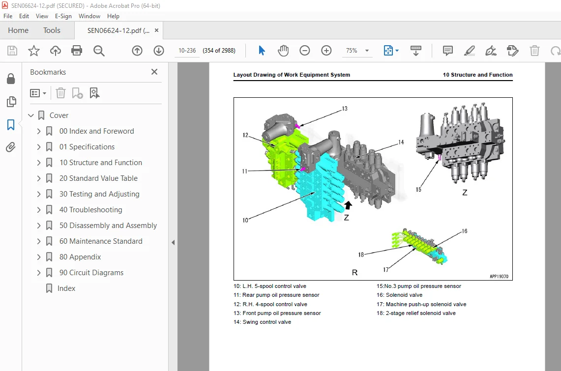
Layout Drawing of Work Equipment System 352
Machine Push-up System 358
Machine Push-up System Diagram 358
Function of Machine Push-up System 359
Heavy Lift System 360
Heavy Lift System Diagram 360
Function of Heavy Lift System 362
Operation of Heavy Lift System 362
Boom Shockless Control System 363
Boom Shockless Control Function System Diagram 363
Function of Boom Shockless Control System 363
Operation of Boom Shockless Control System 363
PPC Lock System 365
System Diagram of PPC Lock 365
Function of PPC Lock System 365
Work Equipment and Travel Automatic Lock System 366
System Diagram of Lock Lever Automatic Lock System 366
Function of Work Equipment and Travel Automatic Lock System 366
Operation of Lock Lever Automatic Lock System 367
Component Parts of Work Equipment System 368
Work Equipment and Swing PPC Valve 368
Solenoid Valve 373
Pilot Circuit Accumulator 379
Swing System 380
Layout Drawing of Swing System 380
Swing Control System Diagram 383
Function of Swing Control System 384
Swing Priority System Diagram 387
Function of Swing Priority System 389
Swing Compensation System Diagram 390
Function of Swing Compensation System 390
Operation of Swing Compensation System 390
Component Parts of Swing System 391
Swing Motor 391
Swing Machinery 403
Swing Circle 405
Travel System 406
Layout Drawing of Travel System 406
System Diagram of Travel Control System 410
Function of Travel Control System 412
Component Parts of Travel System 413
Travel Motor 413
Final Drive 424
Travel PPC Valve 426
Center Swivel Joint 430
Pneumatic System 432
Layout Drawing of Pneumatic System 432
Pneumatic System Diagram 433
Function of Pneumatic System 433
Component Parts of Pneumatic System 434
Air Governor 434
Air Tank 435
Horn Valve 437
Grease Pump 438
Lifting System 439
Hydraulically Operated Stairway System 439
Layout Drawing of Hydraulically Operated Stairway System 439
Hydraulically Operated Stairway System Diagram 440
Function of Hydraulically Operated Stairway System 441
Component Parts of Lifting System 442
Switch Box 442
Proximity Switch Part 443
Control Valve Assembly 444
Undercarriage and Frame 445
Layout Drawing of Undercarriage 445
Specifications of Undercarriage 446
Work Equipment 447
Structure of Work Equipment 447
Function of Work Equipment 447
Work Equipment Clearance Adjustment Shim 448
Function of Work Equipment Clearance Adjustment Shim 448
Bucket Clearance Adjustment Shim 448
Function of Bucket Clearance Adjustment Shim 448
CAB Related Parts 449
CAB 449
Structure of CAB 449
CAB Mount 450
Structure of CAB Mount 450
Function of CAB Mount 450
CAB Tipping Stopper 451
Structure of CAB Tipping Stopper 451
Function of CAB Tipping Stopper 451
20 Standard Value Table 453
Table of Contents 454
Standard Value Table for Engine 455
Standard Value Table for Engine: PC1250-11 455
Standard Value Table for Engine: PC1250SP-11 460
Standard Value Table for Engine: PC1250LC-11 465
Standard Value Table for Machine 470
Standard Value Table for Machine: PC1250-11 470
Standard Value Table for Machine: PC1250SP-11 484
Standard Value Table for Machine: PC1250LC-11 498
Standard Value Table for Machine: PC1250-11 (Loading Shovel Specification) 512
Machine Posture and Procedures to Measure Performance 527
Machine Posture and Procedures to Measure Performance (Loading Shovel Specification) 531
30 Testing and Adjusting 535
Table of Contents 536
Precautions Before Work 540
Related Information on Testing and Adjusting 541
Tools for Testing and Adjusting 541
Sketch of Tools for Testing and Adjusting 548
Engine and Cooling System 549
Examine Engine Speed 549
How to Examine Engine Speed 549
Examine Boost Pressure 552
How to Examine Boost Pressure on Machine Monitor 552
How to Examine Boost Pressure by Testing Tool 553
Examine Exhaust Gas Temperature 554
How to Examine Exhaust Gas Temperature 554
Examine Exhaust Gas Color 556
How to Examine Exhaust Gas Color with the Handy Smoke Checker 556
How to Examine Exhaust Gas Color with Smoke Meter 557
Examine Mass Air Flow and Temperature Sensor 560
How to Examine Mass Air Flow and Temperature Sensor 560
Examine and Adjust Valve Clearance 562
How to Examine Valve Clearance 562
How to Adjust Valve Clearance 563
Examine Compression Pressure 565
How to Examine Compression Pressure 565
Examine Blowby Pressure 569
How to Examine Blowby Pressure 569
Examine Engine Oil Pressure 571
How to Examine Engine Oil Pressure on Machine Monitor 571
How to Examine Engine Oil Pressure by Testing Tool 571
Examine EGR Valve and VGT Oil Pressure 573
How to Examine EGR Valve and VGT Oil Pressure 573
Examine Fuel Pressure 574
How to Examine Fuel Pressure 574
Examine Fuel Return Rate and Leakage 576
How to Examine Fuel Return Rate and Leakage 577
Bleed Air from Fuel System 581
How to Bleed Air from Fuel System 581
Examine Fuel Circuit for Leakage 583
How to Examine Fuel System for Leakage 583
Examine Supply Pump 585
How to Examine Supply Pump 585
Handle Cylinder Cut-out Mode Operation 588
Examine Alternator 589
How to Examine Alternator 589
Handle No-Injection Cranking Operation 590
Clean Fuel Doser 591
How to Clean Fuel Doser 591
Write Injector Compensation Value to Engine Controller 594
How to Write Injector Compensation Value 594
Write Correction for Ash in Soot Accumulation to Engine Controller 600
How to Write Correction for Ash in Soot Accumulation to Engine Controller 600
Power Train 601
Examine Swing Circle Bearing Clearance 601
How to Examine Swing Circle Bearing Clearance 601
Undercarriage and Frame 603
Examine Sprocket Wear 603
How to Examine Sprocket Wear 603
Examine and Adjust Track Tension 604
How to Examine Track Tension 604
How to Adjust Track Tension 604
Hydraulic System 606
Release Remained Pressure in Hydraulic Circuit 606
How to Release Remained Pressure in Hydraulic System 606
How to Release Remained Pressure from Swing Motor Circuit 609
How to Release Remained Pressure from Travel Motor Circuit 609
Examine and Adjust Oil Pressure in Work Equipment, Swing, and Travel Circuits 611
How to Examine Oil Pressure in Work Equipment, Swing, and Travel Circuits 614
How to Adjust Oil Pressure in Work Equipment, Swing, and Travel Circuits 621
Examine and Adjust Oil Pressure in Control Circuit 625
How to Examine Oil Pressure in Control Circuit 625
How to Adjust Oil Pressure in Control Circuit 626
Examine and Adjust Piston Pump Control Oil Pressure 627
How to Examine TVC Valve Outlet Pressure 627
How to Examine CO Valve + NC Valve Outlet Pressure of No 1 and No 2 Pumps 628
How to Examine CO Valve + NC Valve Outlet Pressure of No 3 Pump 629
How to Examine Jet Sensor Outlet Differential Pressure of 4-Spool Control Valve on the Right Side and 5-Spool Control Valve on the Left Side 630
How to Examine Jet Sensor Outlet Differential Pressure of 4-Spool Control Valve for Swing 631
How to Adjust TVC Valve 632
How to Adjust CO Valve + NC Valve of No 1 and No 2 Pumps 633
How to Adjust CO Valve + NC Valve of No 3 Pump 634
How to Adjust Jet Sensor of 4-Spool Control Valve on the Right Side and 5-Spool Control Valve on the Left Side 634
How to Adjust Jet Sensor of 4-Spool Control Valve for Swing 635
Examine Servo Piston Stroke 636
How to Examine Servo Piston Stroke 636
Examine Outlet Pressure of Solenoid Valve 638
How to Examine Outlet Pressure of Solenoid Valve 638
Operating Condition of Solenoid Valve 640
Examine PPC Valve Outlet Pressure 643
How to Examine Outlet Pressure in PPC Valve 643
Examine Swing PPC Shuttle Valve Outlet Pressure 645
How to Examine Swing PPC Shuttle Valve Outlet Pressure 645
Adjust Play of Work Equipment and Swing PPC Valves 647
How to Adjust Play of Work Equipment and Swing PPC Valves 647
Examine Travel Deviation 648
How to Examine Travel Deviation 648
Examine Cooling Fan Speed 649
How to Examine Cooling Fan Speed 649
Examine Aftercooler Fan Speed 650
How to Examine Aftercooler Fan Speed 650
Examine Oil Pressure in Fan Pump Circuit 651
How to Examine Oil Pressure in Fan Pump Circuit 651
Examine Aftercooler Fan Pump Circuit Oil Pressure 652
How to Examine Aftercooler Fan Pump Circuit Oil Pressure 652
Examine Fan Pump EPC Electric Current 653
How to Examine Fan Pump EPC Electric Current 653
Examine Fan Pump EPC Solenoid Valve Outlet Pressure 654
How to Examine Fan Pump EPC Solenoid Valve Outlet Pressure 654
Examine Parts Which Cause Hydraulic Drift of Work Equipment 655
How to Examine Parts Which Cause Hydraulic Drift of Boom Cylinder and Bucket Cylinder 655
How to Examine the Parts Which Cause Hydraulic Drift of Arm Cylinder 655
How to Examine Parts that Cause Hydraulic Drift of PPC Valve 656
Examine Oil Leakage 657
How to Examine Oil Leakage from Boom Cylinder 657
How to Examine Oil Leakage from Arm Cylinder 658
How to Examine Oil Leakage from Bucket Cylinder 658
How to Examine Oil Leakage from Swing Motor 659
How to Examine Oil Leakage from Travel Motor 659
How to Examine Oil Leakage of Swivel Joint 660
Bleed Air from Hydraulic System 662
How to Bleed Air from Hydraulic System 663
CAB Related Parts 667
Examine CAB Tipping Stopper 667
How to Examine Cab Tipping Stopper 667
How to Adjust Mirrors 668
Procedure to Adjust Machine Left Front Mirror (A) 668
Procedure to Adjust Regular Position of Machine Left Front Mirror (A) 669
Procedure to Adjust Machine Right Front Mirror (B) 670
Procedure to Adjust Regular Position of Machine Right Front Mirror (B) 671
Procedure to Adjust Machine Right Front Mirror (C) 672
Procedure to Adjust Regular Position of Machine Right Front Mirror (C) 673
Electrical System 675
Set and Operate Machine Monitor 675
Operator Mode 679
Function to Show Technician Identification Status Screen 679
Function to Show Operator Identification Input Screen 679
Examine Function by LCD (Liquid Crystal Display) 680
Examine Function of Service Meter 680
Usage Limitation and Maintenance Password Change Function 680
Service Mode 683
How to Operate Service Mode 683
How to See Pre-defined Monitoring Information 685
How to Examine Self-Define Monitor Information 689
Abnormality Record Menu 699
How to See Maintenance Record 703
Maintenance Mode Setting 704
How to Set Phone Number Entry 708
Default Menu 710
Diagnostic Tests Menu 718
Adjustment Menu 728
No-Injection Cranking Operation 734
KOMTRAX Settings Menu 736
How to Show Service Message 738
How to Operate Snap Shot 739
How to Start Up KOMTRAX Terminal 741
Default Setting of KOMTRAX Plus Controller 747
Default Setting of KOMTRAX Plus Controller 747
Default Setting of Wireless LAN Modem 750
Default Setting of Wireless LAN Modem 750
How to Examine Wireless LAN Modem Communication 751
Download Data from KOMTRAX Plus Controller 753
How to Download Data from KOMTRAX Plus Controller 753
How to Download Data from Service Connector 755
How to Download Data from Wireless LAN (Wireless LAN Spec) 756
Adjust After Replacement of KOMTRAX Plus Controller 757
How to Adjust After Replacement of KOMTRAX Plus Controller 757
Adjust After Replacement of Wireless LAN Modem 760
How to Adjust After Replacement of Wireless LAN Modem 760
Adjust KomVision Camera Angle 763
How to Adjust KomVision Camera Angle 764
Adjust KomVision Related Function 766
Setting of KomVision (Main Setting) 767
Setting of KomVision (Camera Setting) 769
Setting of KomVision (Camera Calibration) 771
KomVision screen – Check 12 m visibility 784
Set Region of Bluetooth(R) Compatible Radio 787
How to Set Region of Bluetooth(R) Compatible Radio 787
Handle Voltage Circuit of Engine Controller 789
Handle Battery Disconnect Switch 790
Examine Diodes 791
How to Examine Diodes by Digital Tester 791
How to Examine Diodes by Analog Tester 791
Pm Clinic 792
Pm Clinic Service 792
Pm Clinic Check Sheet: PC1250-11 797
Pm Clinic Check Sheet: PC1250SP-11 810
Pm Clinic Check Sheet: PC1250LC-11 823
Perform Quick Pm 836
How to Perform Quick Pm 836
40 Troubleshooting 841
Table of Contents 842
Precautions Before Work 853
Related Information to Troubleshooting 854
General Troubleshooting Points 854
Troubleshooting Points for Aftertreatment System 855
Sequence of Events in Troubleshooting 862
Checks Before Troubleshooting 864
Inspection Procedure Before Troubleshooting 866
Walk-Around Check 866
Test in Accordance with Testing Procedure 868
Examine Fuel Level and Type 868
Examine for Impure Ingredient in Fuel 869
Examine Fuel Prefilter 869
Examine Water Separator, Drain Water and Sediment 870
Replace Fuel Prefilter Cartridge 870
Examine Fuel Main Filter 871
Examine Engine Oil Level (Oil Quantity in Oil Pan) 873
Examine Coolant Level (Reservoir Tank) 874
Examine Air Cleaner Clogging 875
Clean Outer Element 875
Replace Element 878
Examine Hydraulic Oil Level 878
Examine Hydraulic Oil Strainer 880
Examine Hydraulic Oil Filter 881
Examine Oil Level in Swing Machinery Case 882
Examine Oil Level in PTO Case 884
Examine PTO Lubrication Filter Strainer 884
Examine Oil Level in Final Drive Case 885
Bleed Air from Fuel System 885
Bleed Air from Hydraulic System 885
How to Examine Electric Equipment 885
Preparation for Troubleshooting of Electrical System 891
Preparation for Troubleshooting of Machine Monitor 891
Preparation for Troubleshooting of Engine Controller 891
Preparation for Troubleshooting of Pump Controller 891
Preparation for Troubleshooting of KOMTRAX Terminal 892
Preparation for Troubleshooting of KOMTRAX Plus Controller 892
Preparation for Troubleshooting of KomVision Controller 892
How to Disconnect and Connect Connector with a Special Lock 892
Procedure for Troubleshooting 897
Symptom and Troubleshooting Numbers 900
Information Shown in Troubleshooting Table 905
How to Diagnose Open Circuit of Hydraulic Pressure Sensor System Wiring Harness 907
Connector List and Layout 910
Connector List and Layout (Loading Shovel Specification) 926
Connector Contact Connection Table 943
T-Branch Box and T-Branch Adapter Table 983
Fuse Location Table 989
Precautions When You Clean and Replace KDPF (KCSF and KDOC) 992
Prepare of Short Socket Adapter (For Failure Codes [CA1883], [CB1883], [CA3135] and [CB3135]) 996
Failure Code Table 998
Troubleshooting by Failure Code (Display of Code) 1016
Failure Code [879AKA] 1016
Failure Code [879AKB] 1017
Failure Code [879BKA] 1018
Failure Code [879BKB] 1020
Failure Code [879CKA] 1022
Failure Code [879CKB] 1023
Failure Code [879DKZ] 1024
Failure Code [879EMC] 1026
Failure Code [879FMC] 1027
Failure Code [879GKX] 1028
Failure Code [8800ZG] 1030
Failure Code [989L00] 1031
Failure Code [989M00] 1032
Failure Code [989N00] 1033
Failure Code [A1U0N3] 1034
Failure Code [A1U0N4] 1036
Failure Code [AA10NX] 1038
Failure Code [AB00KE] 1040
Failure Code [AQ00N3] 1042
Failure Code [AQ00N4] 1043
Failure Code [AQ10N3] 1044
Failure Code [B@BAZG] 1045
Failure Code [B@BAZK] 1046
Failure Code [B@BCNS] 1048
Failure Code [B@BCZK] 1049
Failure Code [B@CBNS] 1051
Failure Code [B@HANS] 1053
Failure Code [CA115] 1054
Failure Code [CA122] 1058
Failure Code [CA123] 1060
Failure Code [CA131] 1062
Failure Code [CA132] 1064
Failure Code [CA135] 1066
Failure Code [CA141] 1068
Failure Code [CA144] 1070
Failure Code [CA145] 1072
Failure Code [CA153] 1074
Failure Code [CA154] 1076
Failure Code [CA187] 1078
Failure Code [CA212] 1080
Failure Code [CA213] 1082
Failure Code [CA221] 1084
Failure Code [CA222] 1086
Failure Code [CA227] 1088
Failure Code [CA234] 1090
Failure Code [CA238] 1091
Failure Code [CA239] 1093
Failure Code [CA271] 1095
Failure Code [CA272] 1097
Failure Code [CA273] 1098
Failure Code [CA274] 1100
Failure Code [CA322] 1101
Failure Code [CA323] 1103
Failure Code [CA324] 1105
Failure Code [CA325] 1107
Failure Code [CA331] 1109
Failure Code [CA332] 1111
Failure Code [CA343] 1113
Failure Code [CA351] 1115
Failure Code [CA352] 1117
Failure Code [CA356] 1119
Failure Code [CA357] 1121
Failure Code [CA386] 1123
Failure Code [CA441] 1125
Failure Code [CA442] 1127
Failure Code [CA449] 1129
Failure Code [CA451] 1130
Failure Code [CA452] 1132
Failure Code [CA515] 1134
Failure Code [CA516] 1135
Failure Code [CA553] 1136
Failure Code [CA555] 1137
Failure Code [CA556] 1139
Failure Code [CA559] 1141
Failure Code [CA595] 1146
Failure Code [CA687] 1148
Failure Code [CA689] 1150
Failure Code [CA691] 1152
Failure Code [CA692] 1154
Failure Code [CA697] 1156
Failure Code [CA698] 1157
Failure Code [CA731] 1158
Failure Code [CA778] 1162
Failure Code [CA1117] 1164
Failure Code [CA1135] 1166
Failure Code [CA1257] 1169
Failure Code [CA1664] 1170
Failure Code [CA1691] 1172
Failure Code [CA1695] 1175
Failure Code [CA1696] 1177
Failure Code [CA1843] 1179
Failure Code [CA1844] 1181
Failure Code [CA1879] 1183
Failure Code [CA1881] 1185
Failure Code [CA1883] 1187
Failure Code [CA1921] 1190
Failure Code [CA1922] 1192
Failure Code [CA1923] 1196
Failure Code [CA1924] 1198
Failure Code [CA1925] 1200
Failure Code [CA1927] 1202
Failure Code [CA1928] 1204
Failure Code [CA1942] 1206
Failure Code [CA1963] 1208
Failure Code [CA1977] 1212
Failure Code [CA1993] 1214
Failure Code [CA2185] 1216
Failure Code [CA2186] 1217
Failure Code [CA2249] 1219
Failure Code [CA2265] 1224
Failure Code [CA2266] 1226
Failure Code [CA2271] 1228
Failure Code [CA2272] 1230
Failure Code [CA2349] 1232
Failure Code [CA2353] 1234
Failure Code [CA2357] 1236
Failure Code [CA2381] 1239
Failure Code [CA2382] 1241
Failure Code [CA2383] 1243
Failure Code [CA2386] 1245
Failure Code [CA2387] 1247
Troubleshooting Flowchart 1251
Failure Code [CA2555] 1252
Failure Code [CA2556] 1254
Failure Code [CA2637] 1256
Failure Code [CA2639] 1259
Failure Code [CA2732] 1261
Failure Code [CA2733] 1263
Failure Code [CA2741] 1265
Failure Code [CA2765] 1266
Failure Code [CA2777] 1267
Failure Code [CA2878] 1269
Failure Code [CA2881] 1272
Failure Code [CA3133] 1276
Failure Code [CA3134] 1278
Failure Code [CA3135] 1280
Failure Code [CA3167] 1283
Failure Code [CA3251] 1286
Failure Code [CA3253] 1288
Failure Code [CA3254] 1292
Failure Code [CA3255] 1295
Failure Code [CA3256] 1298
Failure Code [CA3311] 1300
Failure Code [CA3312] 1302
Failure Code [CA3313] 1304
Failure Code [CA3314] 1305
Failure Code [CA3315] 1306
Failure Code [CA3316] 1309
Failure Code [CA3317] 1310
Failure Code [CA3318] 1311
Failure Code [CA3319] 1314
Failure Code [CA3321] 1315
Failure Code [CA3322] 1316
Failure Code [CA3419] 1319
Failure Code [CA3421] 1321
Failure Code [CA4151] 1323
Failure Code [CA4158] 1326
Failure Code [CA4161] 1327
Failure Code [CA4162] 1329
Failure Code [CA4163] 1331
Failure Code [CA4259] 1333
Failure Code [CA4952] 1335
Failure Code [CA5383] 1337
Failure Code [CB115] 1338
Failure Code [CB187] 1341
Failure Code [CB227] 1343
Failure Code [CB238] 1344
Failure Code [CB239] 1346
Failure Code [CB271] 1348
Failure Code [CB272] 1350
Failure Code [CB273] 1351
Failure Code [CB274] 1353
Failure Code [CB343] 1354
Failure Code [CB352] 1356
Failure Code [CB386] 1358
Failure Code [CB441] 1360
Failure Code [CB442] 1362
Failure Code [CB689] 1364
Failure Code [CB697] 1366
Failure Code [CB698] 1367
Failure Code [CB731] 1368
Failure Code [CB778] 1372
Failure Code [CB1117] 1374
Failure Code [CB1257] 1376
Failure Code [CB1664] 1377
Failure Code [CB1691] 1379
Failure Code [CB1695] 1382
Failure Code [CB1696] 1384
Failure Code [CB1879] 1386
Failure Code [CB1881] 1388
Failure Code [CB1883] 1390
Failure Code [CB1921] 1393
Failure Code [CB1922] 1395
Failure Code [CB1923] 1399
Failure Code [CB1924] 1401
Failure Code [CB1925] 1403
Failure Code [CB1927] 1405
Failure Code [CB1928] 1407
Failure Code [CB1963] 1409
Failure Code [CB1977] 1413
Failure Code [CB1993] 1415
Failure Code [CB2265] 1417
Failure Code [CB2266] 1419
Failure Code [CB2637] 1421
Failure Code [CB2639] 1424
Failure Code [CB2732] 1426
Failure Code [CB2733] 1428
Failure Code [CB2741] 1430
Failure Code [CB2777] 1432
Failure Code [CB2878] 1434
Failure Code [CB2881] 1437
Failure Code [CB3133] 1441
Failure Code [CB3134] 1443
Failure Code [CB3135] 1445
Failure Code [CB3167] 1448
Failure Code [CB3251] 1451
Failure Code [CB3253] 1453
Failure Code [CB3254] 1458
Failure Code [CB3255] 1461
Failure Code [CB3256] 1464
Failure Code [CB3311] 1466
Failure Code [CB3312] 1468
Failure Code [CB3313] 1470
Failure Code [CB3314] 1471
Failure Code [CB3315] 1472
Failure Code [CB3316] 1475
Failure Code [CB3317] 1476
Failure Code [CB3318] 1477
Failure Code [CB3319] 1480
Failure Code [CB3321] 1481
Failure Code [CB3322] 1482
Failure Code [CB4151] 1485
Failure Code [CB4158] 1488
Failure Code [CB4161] 1489
Failure Code [CB4162] 1491
Failure Code [CB4163] 1493
Failure Code [CB4259] 1495
Failure Code [CB4952] 1497
Failure Code [CB5383] 1499
Failure Code [D110KB] 1500
Failure Code [D163KB] 1502
Failure Code [D195KA] 1504
Failure Code [D195KB] 1506
Failure Code [D19JKZ] 1508
Failure Code [D862KA] 1510
Failure Code [D8AQKR] 1511
Failure Code [DA20MC] 1515
Failure Code [DA22KK] 1516
Failure Code [DA25KP] 1518
Failure Code [DA26KP] 1520
Failure Code [DA29KQ] 1522
Failure Code [DA2LKA] 1524
Failure Code [DA2LKB] 1526
Failure Code [DA2QKR] 1528
Failure Code [DA2RKR] 1533
Failure Code [DAF0KM] 1538
Failure Code [DAF0MB] 1539
Failure Code [DAF0MC] 1540
Failure Code [DAF9KQ] 1541
Failure Code [DAFGMC] 1542
Failure Code [DAFLKA] 1543
Failure Code [DAFLKB] 1546
Failure Code [DAFQKR] 1548
Failure Code [DAZ9KQ] 1553
Failure Code [DAZQKR] 1554
Failure Code [DB2QKR] 1557
Failure Code [DB2RKR] 1564
Failure Code [DBP0KM] 1570
Failure Code [DBP0KT] 1571
Failure Code [DBP5KB] 1572
Failure Code [DBP5KY] 1574
Failure Code [DBPQKR] 1576
Failure Code [DBV0MC] 1581
Failure Code [DBV1KK] 1582
Failure Code [DBV5KB] 1584
Failure Code [DBV6KB] 1588
Failure Code [DBVLKA] 1590
Failure Code [DBVLKB] 1592
Failure Code [DBVQKR] 1594
Failure Code [DBVRKR] 1598
Failure Code [DBVVKR] 1602
Failure Code [DBVWKR] 1603
Failure Code [DDNRKA] 1604
Failure Code [DDNRKY] 1606
Failure Code [DDNS00] 1608
Failure Code [DGE5KB] 1610
Failure Code [DGH2KA] 1611
Failure Code [DGH2KB] 1613
Failure Code [DGT3KB] 1615
Failure Code [DGT4KA] 1617
Failure Code [DGT4KB] 1619
Failure Code [DHA4KA] 1621
Failure Code [DHAAMA] 1623
Failure Code [DHABMA] 1624
Failure Code [DHACMA] 1625
Failure Code [DHADMA] 1626
Failure Code [DHPAMA] 1627
Failure Code [DHPAZL] 1629
Failure Code [DHPBMA] 1630
Failure Code [DHPBZL] 1632
Failure Code [DHPGMA] 1633
Failure Code [DHPGZL] 1635
Failure Code [DHPSMA] 1636
Failure Code [DHPTKA] 1638
Failure Code [DHPTKB] 1640
Failure Code [DHS3MA] 1642
Failure Code [DHS4MA] 1645
Failure Code [DHS8MA] 1648
Failure Code [DHS9MA] 1651
Failure Code [DHSAMA] 1654
Failure Code [DHSBMA] 1657
Failure Code [DHSCMA] 1660
Failure Code [DHSDMA] 1663
Failure Code [DHSFMA] 1666
Failure Code [DHSGMA] 1669
Failure Code [DHSHMA] 1672
Failure Code [DHSJMA] 1675
Failure Code [DKR2KA] 1678
Failure Code [DKR2KB] 1680
Failure Code [DKR2NX] 1682
Failure Code [DKR3KA] 1684
Failure Code [DKR3KB] 1686
Failure Code [DKR3NX] 1688
Failure Code [DKULKA] 1690
Failure Code [DKULKB] 1692
Failure Code [DKULKY] 1694
Failure Code [DLM3KA] 1696
Failure Code [DLM3KB] 1698
Failure Code [DLM3MB] 1700
Failure Code [DR10KA] 1701
Failure Code [DR12KA] 1704
Failure Code [DR20KA] 1706
Failure Code [DR21KX] 1708
Failure Code [DR30KA] 1710
Failure Code [DR31KX] 1712
Failure Code [DR40KA] 1714
Failure Code [DUMBKA] 1716
Failure Code [DUMBKB] 1719
Failure Code [DV20KB] 1721
Failure Code [DW41KA] 1723
Failure Code [DW41KB] 1725
Failure Code [DW41KY] 1726
Failure Code [DW43KA] 1727
Failure Code [DW43KB] 1729
Failure Code [DW43KY] 1730
Failure Code [DW45KA] 1731
Failure Code [DW45KB] 1734
Failure Code [DW45KY] 1737
Failure Code [DW48KA] 1739
Failure Code [DW48KB] 1741
Failure Code [DW48KY] 1743
Failure Code [DW4CKY] 1744
Failure Code [DW7BKA] 1746
Failure Code [DW7BKB] 1748
Failure Code [DW7BKY] 1750
Failure Code [DW91KA] 1751
Failure Code [DW91KB] 1753
Failure Code [DW91KY] 1754
Failure Code [DWA5KA] 1755
Failure Code [DWA5KB] 1757
Failure Code [DWA5KY] 1759
Failure Code [DWK0KA] 1761
Failure Code [DWK0KB] 1763
Failure Code [DWK0KY] 1765
Failure Code [DWK2KA] 1766
Failure Code [DWK2KB] 1768
Failure Code [DWK2KY] 1770
Failure Code [DWK8KA] 1771
Failure Code [DWK8KB] 1773
Failure Code [DWK8KY] 1775
Failure Code [DX16KA] 1776
Failure Code [DX16KB] 1778
Failure Code [DXA0KA] 1780
Failure Code [DXA0KB] 1783
Failure Code [DXAXKA] 1785
Failure Code [DXAXKB] 1787
Failure Code [DY20KA] 1789
Failure Code [DY20KA] 1791
Failure Code [DY20MA] 1794
Failure Code [DY20MA] 1796
Failure Code [DY2CKB] 1799
Failure Code [DY2DKB] 1801
Failure Code [DY2DKB] 1803
Failure Code [DY2EKB] 1806
Failure Code [DY2EKB] 1808
Failure Code [DY2FMA] 1811
Failure Code [DY2GKM] 1813
Failure Code [F@BYNR] 1815
Failure Code [F@BYNS] 1816
Failure Code [J100KA] 1817
Failure Code [J100KB] 1819
Failure Code [J100L6] 1821
Failure Code [J190KA] 1822
Failure Code [J190KB] 1824
Failure Code [J190L6] 1826
Failure Code [LA10ZL] 1827
Troubleshooting of Electrical System (E-Mode) 1828
E-1 Engine Does Not Start (Engine Does Not Crank) 1828
E-2 Manual Preheating System Does Not Operate 1835
E-3 Automatic Preheating System Does Not Operate 1838
E-4 While Preheating is in Operation, Preheating Monitor Does Not Come On 1840
E-5 When Starting Switch is Turned to ON Position, Machine Monitor Shows Nothing 1842
E-6 While Starting Switch is Turned to ON Position (with Engine Stopped), Engine Oil Level Monitor Comes On in Yellow 1845
E-7 While Starting Switch is Turned to ON Position (with Engine Stopped), Radiator Coolant Level Monitor Comes On in Yellow 1846
E-8 Engine Coolant Temperature Monitor Comes On While Engine is in Operation 1847
E-9 Hydraulic Oil Temperature Monitor Comes On in White While Engine Runs 1848
E-10 Air Cleaner Clogging Monitor Comes On in Yellow While Engine Runs 1849
E-11 Charge Level Monitor Comes On in Red While Engine is in Operation 1850
E-12 Fuel Level Monitor Comes On in Red While Engine Runs 1851
E-13 Engine Coolant Temperature Monitor Comes On in Red While Engine is in Operation 1852
E-14 Engine Oil Pressure Monitor Comes on in Red While Engine is in Operation 1853
E-15 Hydraulic Oil Temperature Monitor Comes on in Red While Engine is in Operation 1854
E-16 Fuel Gauge Display Does Not Move from Minimum or Maximum 1855
E-17 Display of Fuel Gauge is Different from Actual Fuel Level 1857
E-18 Coolant Temperature Gauge Display Does Not Move from Minimum or Maximum 1858
E-19 Display of Coolant Temperature Gauge is Different from Actual Coolant Temperature 1859
E-20 Hydraulic Oil Temperature Gauge Display Does Not Move from Minimum or Maximum 1860
E-21 Display of Hydraulic Oil Temperature Gauge is Different from Actual Oil Temperature 1862
E-22 Some Areas of Machine Monitor Screen are Not Shown 1863
E-23 Function Switch Does Not Operate 1864
E-24 Automatic Warm-up System Does Not Work (in Cold Weather) 1865
E-25 When Auto-Decelerator Switch is Operated, Auto-Decelerator Monitor Does Not Come On or Does Not Go Out 1866
E-26 Auto-Decelerator is Not Operated or Canceled with Lever 1867
E-27 When Working Mode Switch is Operated, Working Mode Selection Screen is Not Shown 1868
E-28 When Working Mode is Changed, Setting of Engine and Hydraulic Pump is Not Changed 1869
E-29 When Travel Speed Switch is Operated, Travel Speed Monitor Does Not Change 1870
E-30 When Travel Speed Selection is Changed, Actual Travel Speed Does Not Change 1871
E-31 Alarm Buzzer Cannot be Canceled 1872
E-32 Service Meter is Not Shown, While Starting Switch is in OFF Position 1873
E-33 Service Mode Cannot be Selected 1874
E-34 All of Work Equipment, Swing, and Travel Mechanism Do Not Move 1875
E-35 All Work Equipment, Swing and Travel Do Not Lock 1878
E-36 When Swing Brake Cancel Switch is Set to Cancel Position, Machine Cannot Swing 1880
E-37 When Swing Brake Cancel Switch is Set to Normal Position, Swing Holding Brake Does Not Operate 1883
E-38 Alarm Does Not Sound During Travel 1885
E-39 Travel Alarm Does Not Stop When Machine Stops 1887
E-40 Horn Does Not Sound 1888
E-41 Horn Does Not Stop 1891
E-42 When Wiper Switch is Operated, Wiper Monitor Does Not Come On or Go Out 1893
E-43 Wiper Does Not Operate When Wiper Switch is Operated (Single Wiper Specification) 1894
E-44 Wiper Does Not Operate When Wiper Switch is Operated (Double Wiper Specification) 1896
E-45 Fuel Feed Pump Does Not Operate or Stop Automatically 1898
E-46 Window Washer Does Not Operate When Window Washer Switch is Operated 1901
E-47 “Boom RAISE” is Not Shown Correctly with Monitoring Function 1902
E-48 “Boom LOWER” is Not Shown Correctly with Monitoring Function 1903
E-49 “Arm OUT” is Not Shown Correctly with Monitoring Function 1904
E-50 “Arm IN” is Not Shown Correctly with Monitoring Function 1905
E-51 “Bucket DUMP” is Not Shown Correctly with Monitoring Function 1906
E-52 “Bucket CURL” is Not Shown Correctly with Monitoring Function 1907
E-53 “Swing” is Not Shown Correctly with Monitoring Function 1908
E-54 “Travel” is Not Shown Correctly with Monitoring Function 1909
E-55 KOMTRAX System Does Not Operate Correctly 1910
E-56 Machine Push-Up Function Cannot be Canceled 1911
E-57 Machine Push-Up Function Does Not Operate 1913
E-58 Step Light Does Not Come On 1914
E-59 Step Light Does Not Go Out 1917
E-60 Boom Shockless Function Cannot be Canceled 1919
E-61 Boom Shockless Function Does Not Work 1921
E-62 Bottom Dump Cannot be Operated 1922
Troubleshooting for Hydraulic and Mechanical Systems (H Mode) 1925
H-1 All Work Equipment, Travel, and Swing Speed or Power is Low 1925
H-2 Engine Speed Drops Significantly or Engine Stalls 1927
H-3 All Work Equipment, Swing and Travel Do Not Work 1928
H-4 Unusual Noise is Heard from Around Work Equipment Pump 1930
H-5 Boom Speed or Power is Low in Normal Mode 1931
H-6 Boom RAISE Speed or Power is Low in Heavy Lift Mode 1932
H-7 Boom LOWER Speed or Power is Low in Machine Push Up Mode 1933
H-8 Arm Speed or Power is Low 1934
H-9 Bucket Speed or Power is Low 1935
H-10 Boom Does Not Operate 1936
H-11 Arm Does Not Operate 1937
H-12 Bucket Does Not Operate 1938
H-13 Hydraulic Drift of Boom is Large 1939
H-14 Hydraulic Drift of Arm is Large 1940
H-15 Hydraulic Drift of Bucket is Large 1941
H-16 Time Lag of Boom is Large 1942
H-17 Time Lag of Arm is Large 1943
H-18 Time Lag of Bucket is Large 1944
H-19 Boom Shockless Function Does Not Work or Cannot be Released 1945
H-20 Machine Accidentally Turns to One Side When Machine Travels (It Turns in the Same Direction When Traveling Forward and Reverse) 1946
H-21 Machine Accidentally Turns to One Side When Machine Travels (It Turns in the Different Directions When Traveling Forward and Reverse) 1948
H-22 Travel Deviation is Large at Start of Travel Only When Travel Lever is Fully Moved 1949
H-23 Regardless of the Stroke of the Travel Lever, Travel Deviation is Large at Start of Traveling 1950
H-24 Travel Deviation is Large at Mixed Operation 1951
H-25 Travel Speed or Power is Low 1952
H-26 Only the One Side Track Can Operate (Machine Does Not Travel FORWARD or REVERSE) 1953
H-27 Only the One Side Track Can Operate (in Either Forward or Reverse Direction) 1954
H-28 Travel Speed Does Not Change, or Travel Speed is Too Slow or Fast 1955
H-29 Upper Structure Does Not Swing to Right and Left 1956
H-30 Upper Structure Swings Only to Right or Left 1957
H-31 Swing Acceleration or Swing Speed is Low in Lateral Directions (Right and Left) 1958
H-32 Swing Acceleration Performance is Unsatisfactory or Swing Speed is Slow in Only One Direction 1959
H-33 In Mixed Operation of Work Equipment, Swing Speed or Power is Low 1960
H-34 Swing Acceleration or Swing Speed is Low During Mixed Operation with Boom in Swing Priority Mode 1961
H-35 Upper Structure Overruns Too Much When It Stops Swing Operation in Lateral Directions of Right and Left 1962
H-36 Upper Structure Speed is High When It Stops Swing Operation (on One Side) 1963
H-37 Shock is Large When Upper Structure Stops Swing Operation (Right and Left) 1964
H-38 Shock is Large When Upper Structure Stops Swing Operation (in Only Right of Left Direction) 1965
H-39 Large Unusual Noise is Heard When Upper Structure Stops Swing Operation (in Right and Left Directions) 1966
H-40 Large Unusual Noise is Heard When Upper Structure Stops Swing Operation in Only One Direction 1967
H-41 Swing Drift on a Slope is Large 1968
H-42 Fan Rotation is Abnormal (Such as Excessive Noise or Vibration of Fan, or Overheating) 1969
H-43 Bottom Dump Cannot be Moved 1970
Troubleshooting of Engine (S-Mode) 1971
Information Shown in Troubleshooting Table (S-Mode) 1971
S-1 Engine Does Not Crank When Starting Switch is Turned to Start Position 1972
S-2 Engine Cranks but No Exhaust Smoke Comes Out 1973
S-3 Fuel is Injected but Engine Does Not Start (Misfiring: Engine Cranks but Does Not Start) 1974
S-4 Engine Startability is Unsatisfactory 1975
S-5 Engine Does Not Pick Up Smoothly 1977
S-6 Engine Stops During Operation 1979
S-7 Engine Runs Rough or is Not Stable 1981
S-8 Engine Lacks Power 1982
S-9 KDPF Becomes Clogged in a Short Time 1984
S-10 Engine Oil Consumption is Excessive 1986
S-11 Oil Becomes Dirty Quickly 1987
S-12 Fuel Consumption is Excessive 1988
S-13 Oil is in Coolant (or Coolant Spurts Back or Coolant 1989
S-14 Oil Pressure Drops 1990
S-15 Fuel Mixes Into Engine Oil 1992
S-16 Water Mixes Into Engine Oil (Milky) 1993
S-17 Coolant Temperature Increases Too High (Overheating) 1994
S-18 Unusual Noise is Heard 1996
S-19 Vibration is Excessive 1997
S-20 Air Cannot be Bled from Fuel Circuit 1998
S-21 Active Regeneration is Done Frequently 1999
S-22 Active Regeneration Continues Long 2000
S-23 White Smoke is Exhausted During Active Regeneration 2001
50 Disassembly and Assembly 2003
Table of Contents 2004
Precautions Before Work 2009
Related Information on Disassembly and Assembly 2010
How to Read This Manual 2010
Coating Materials List 2012
Special Tool List 2017
Sketches of Special Tools 2036
Engine and Cooling System 2043
Remove and Install Supply Pump Assembly 2043
How to Remove Supply Pump Assembly 2043
How to Install Supply Pump Assembly 2055
Remove and Install Injector Assembly 2069
How to Remove Injector Assembly 2070
How to Install Injector Assembly 2080
Remove and Install Fuel Doser Assembly 2093
How to Remove Fuel Doser Assembly 2093
How to Install Fuel Doser Assembly 2096
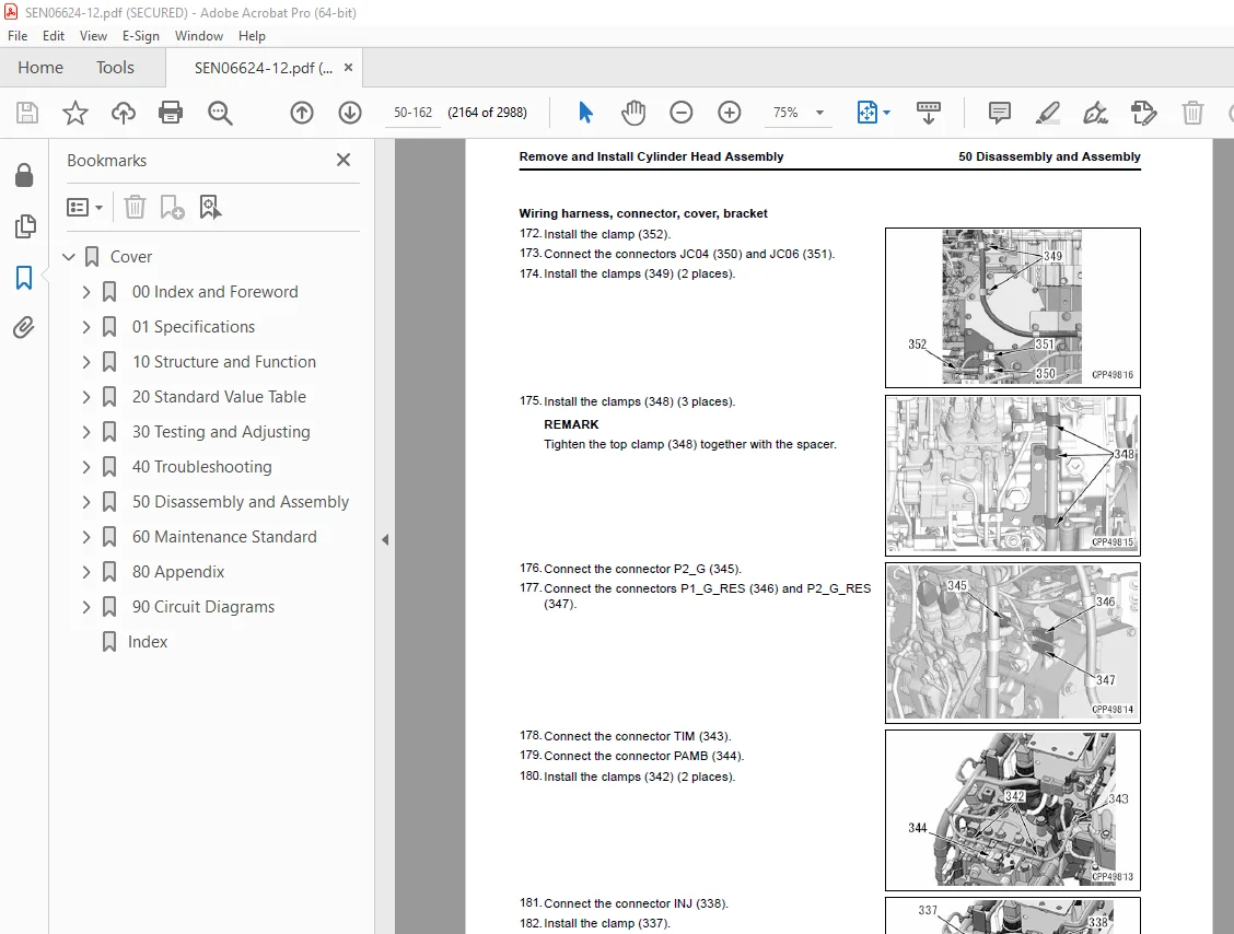
Remove and Install Cylinder Head Assembly 2099
How to Remove Cylinder Head Assembly 2100
How to Install Cylinder Head Assembly 2139
Remove and Install EGR Valve Assembly 2190
How to Remove EGR Valve Assembly 2190
How to Install EGR Valve Assembly 2194
Remove and Install EGR Cooler Assembly 2198
How to Remove EGR Cooler Assembly 2198
How to Install EGR Cooler Assembly 2204
Remove and Install Starter Assembly 2213
How to Remove Starting Motor Assembly 2213
How to Install Starting Motor Assembly 2213
Remove and Install Alternator Belt 2215
How to Remove Alternator Belt 2215
How to Install Alternator Belt 2216
Remove and Install Radiator Assembly 2218
How to Remove Radiator Assembly 2218
How to Install Radiator Assembly 2222
Remove and Install Hydraulic Oil Cooler Assembly 2227
How to Remove Hydraulic Oil Cooler Assembly 2227
How to Install Hydraulic Oil Cooler Assembly 2232
Remove and Install Aftercooler Assembly 2238
How to Remove Aftercooler Assembly 2238
How to Install Aftercooler Assembly 2244
Remove and Install Cooling Fan Motor Assembly 2250
How to Remove Cooling Fan Motor Assembly 2250
How to Install Cooling Fan Motor Assembly 2263
Remove and Install Engine, PTO, and Hydraulic Pump Assembly 2275
How to Remove Engine PTO and Hydraulic Assembly 2275
How to Install Engine PTO and Hydraulic Assembly 2291
Remove and Install Engine Front Oil Seal 2307
How to Remove Engine Front Oil Seal 2307
How to Install Engine Front Oil Seal 2310
Remove and Install Engine Rear Oil Seal 2314
How to Remove Engine Rear Oil Seal 2314
How to Install Engine Rear Oil Seal 2315
Remove and Install Fuel Cooler Assembly 2319
How to Remove Fuel Cooler Assembly 2319
How to Install Fuel Cooler Assembly 2320
Remove and Install Engine Hood Assembly 2322
How to Remove Engine Hood Assembly 2322
How to Install Engine Hood Assembly 2328
Remove and Install Fuel Tank Assembly 2335
How to Remove Fuel Tank Assembly 2335
How to Install Fuel Tank Assembly 2340
Remove and Install KDPF Assembly 2345
How to Remove KDPF Assembly 2345
How to Install KDPF Assembly 2351
Disassemble and Assemble KDPF Assembly 2358
How to Disassemble KDPF Assembly 2359
How to Assemble KDPF Assembly 2364
Remove and Install Bellows Pipe Assembly 2372
How to Remove Bellows Pipe Assembly 2372
How to Install Bellows Pipe Assembly 2376
Remove and Install KCCV Assembly 2380
How to Remove KCCV Assembly 2380
How to Install KCCV Assembly 2382
Remove and Install Air Cleaner Assembly 2384
How to Remove Air Cleaner Assembly 2384
How to Install Air Cleaner Assembly 2384
Remove and Install Air Conditioner Compressor Assembly 2386
How to Remove Air Conditioner Compressor Assembly 2386
How to Install Air Conditioner Compressor Assembly 2387
Remove and Install Air Conditioner Condenser Assembly 2389
How to Remove Air Conditioner Condenser Assembly 2389
How to Install Air Conditioner Condenser Assembly 2390
Power Train 2393
Disassemble and Assemble PTO Assembly 2393
How to Disassemble PTO Assembly 2393
How to Assemble PTO Assembly 2395
Remove and Install PTO Assembly 2399
How to Remove PTO Assembly 2399
How to Install PTO Assembly 2401
Remove and Install Travel Motor and Final Drive Assembly 2404
How to Remove Travel Motor and Final Drive Assembly 2404
How to Install Travel Motor and Final Drive Assembly 2405
Disassemble and Assemble Final Drive Assembly 2406
How to Disassemble Final Drive Assembly 2406
How to Assemble Final Drive Assembly 2411
Remove and Install Swing Motor and Swing Machinery Assembly 2419
How to Remove Swing Motor and Swing Machinery Assembly 2419
How to Install Swing Motor and Swing Machinery Assembly 2421
Disassemble and Assemble Swing Machinery Assembly 2424
How to Disassemble Swing Machinery Assembly 2424
How to Assemble Swing Machinery Assembly 2428
Remove and Install Swing Circle Assembly 2434
How to Remove Swing Circle Assembly 2434
How to Install Swing Circle Assembly 2435
Undercarriage and Frame 2436
Remove and Install Idler Assembly 2436
How to Remove Idler Assembly 2436
How to Install Idler Assembly 2437
Disassemble and Assemble Recoil Spring Assembly 2438
How to Disassemble Recoil Spring Assembly 2438
How to Assemble Recoil Spring Assembly 2439
Remove and Install Track Roller Assembly 2440
How to Remove Track Roller Assembly 2440
How to Install Track Roller Assembly 2441
Remove and Install Carrier Roller Assembly 2443
How to Remove Carrier Roller Assembly 2443
How to Install Carrier Roller Assembly 2444
Disassemble and Assemble One Track Link Assembly in Field 2445
How to Disassemble One Track Link Assembly in Field 2447
How to Assemble One Track Link Assembly in Field 2448
Separate and Connect Track Assembly 2451
How to Separate Track Assembly 2452
How to Install Track Assembly 2453
Disassemble and Assemble Idler Assembly 2454
How to Disassemble Idler Assembly 2454
How to Assemble Idler Assembly 2456
Disassemble and Assemble Idler Adjustment Cylinder Assembly 2459
How to Disassemble Idler Adjustment Cylinder Assembly 2459
How to Assemble Idler Adjustment Cylinder Assembly 2460
Disassemble and Assemble Track Roller Assembly 2461
How to Disassemble Track Roller Assembly 2461
How to Assemble Track Roller Assembly 2462
Disassemble and Assemble Carrier Roller Assembly 2465
How to Disassemble Carrier Roller Assembly 2465
How to Assemble Carrier Roller Assembly 2466
Remove and Install Revolving Frame Assembly 2468
How to Remove Revolving Frame Assembly 2468
How to Install Revolving Frame Assembly 2469
Remove and Install Counterweight Assembly 2471
How to Remove Counterweight Assembly 2471
How to Install Counterweight Assembly 2473
Hydraulic System 2475
Remove and Install Center Swivel Joint Assembly 2475
How to Remove Center Swivel Joint Assembly 2475
How to Install Center Swivel Joint Assembly 2476
Disassemble and Assemble Center Swivel Joint Assembly 2478
How to Disassemble Center Swivel Joint Assembly 2479
How to Assemble Center Swivel Joint Assembly 2480
Remove and Install Hydraulic Tank Assembly 2481
How to Remove Hydraulic Tank Assembly 2481
How to Install Hydraulic Tank Assembly 2485
Remove and Install Hydraulic Pump Assembly 2490
How to Remove Hydraulic Pump Assembly 2490
How to Install Hydraulic Pump Assembly 2502
Remove and Install Control Valve Assembly 2513
How to Remove Control Valve Assembly 2513
How to Install Control Valve Assembly 2518
Remove and Install Swing Motor Assembly 2525
How to Remove Swing Motor Assembly 2525
How to Install Swing Motor Assembly 2526
Disassemble and Assemble Work Equipment PPC Valve Assembly 2528
How to Disassemble Work Equipment PPC Valve Assembly 2528
How to Assemble Work Equipment PPC Valve Assembly 2529
Disassemble and Assemble Travel PPC Valve Assembly 2531
How to Disassemble Travel PPC Valve Assembly 2531
How to Assemble Travel PPC Valve Assembly 2532
Disassemble and Assemble Grease Gun Assembly 2534
How to Disassemble Grease Gun Assembly 2534
How to Assemble Grease Gun Assembly 2534
Work Equipment 2535
Remove and Install Bucket Cylinder Assembly 2535
How to Remove Bucket Cylinder Assembly 2535
How to Install Bucket Cylinder Assembly 2536
Remove and Install Bucket Cylinder Assembly (Loading Shovel Specification) 2538
How to Remove Bucket Cylinder Assembly (Loading Shovel Specification) 2538
How to Install Bucket Cylinder Assembly (Loading Shovel Specification) 2539
Remove and Install Arm Cylinder Assembly 2541
How to Remove Arm Cylinder Assembly 2541
How to Install Arm Cylinder Assembly 2543
Remove and Install Arm Cylinder Assembly (Loading Shovel Specification) 2545
How to Remove Arm Cylinder Assembly (Loading Shovel Specification) 2545
How to Install Arm Cylinder Assembly (Loading Shovel Specification) 2547
Remove and Install Boom Cylinder Assembly 2549
How to Remove Boom Cylinder Assembly 2549
How to Install Boom Cylinder Assembly 2550
Remove and Install Boom Cylinder Assembly (Loading Shovel Specification) 2552
How to Remove Boom Cylinder Assembly (Loading Shovel Specification) 2552
How to Install Boom Cylinder Assembly (Loading Shovel Specification) 2553
Remove and Install Bucket Assembly 2556
How to Remove Bucket Assembly 2557
How to Install Bucket Assembly 2558
Remove and Install Bucket Assembly (Loading Shovel Specification) 2560
How to Remove Bucket Assembly (Loading Shovel Specification) 2560
How to Install Bucket Assembly (Loading Shovel Specification) 2561
Remove and Install Arm Assembly 2563
How to Remove Arm Assembly 2563
How to Install Arm Assembly 2564
Remove and Install Arm Assembly (Loading Shovel Specification) 2566
How to Remove Arm Assembly (Loading Shovel Specification) 2566
How to Install Arm Assembly (Loading Shovel Specification) 2567
Remove and Install Boom Assembly 2569
How to Remove Boom Assembly 2569
How to Install Boom Assembly 2571
Remove and Install Boom Assembly (Loading Shovel Specification) 2573
How to Remove Boom Assembly (Loading Shovel Specification) 2573
How to Install Boom Assembly (Loading Shovel Specification) 2575
Disassemble and Assemble Work Equipment Cylinder Assembly 2577
How to Disassemble Work Equipment Cylinder Assembly 2578
How to Assemble Work Equipment Cylinder Assembly 2580
Disassemble and Assemble Bottom Dump Cylinder Assembly (Loading Shovel Specification) 2585
How to Disassemble Bottom Dump Cylinder Assembly (Loading Shovel Specification) 2585
How to Assemble Bottom Dump Cylinder Assembly (Loading Shovel Specification) 2591
CAB Related Parts 2596
Remove and Install Top Guard Assembly 2596
How to Remove Top Guard Assembly 2596
How to Install Top Guard Assembly 2598
Remove and Install Operator Cab Assembly 2600
How to Remove Operator Cab Assembly 2600
How to Install Operator Cab Assembly 2609
Remove and Install Operator Cab Glass (Adhered Glass) 2619
How to Remove Operator Cab Glass (Adhered Glass) 2621
How to Install Operator Cab Glass (Adhered Glass) 2621
Remove and Install Front Window Assembly 2631
How to Remove Front Window Assembly 2631
How to Install Front Window Assembly 2634
Remove and Install Floor Frame Assembly 2640
How to Remove Floor Frame Assembly 2640
How to Install Floor Frame Assembly 2646
Remove and Install Air Conditioner Unit Assembly 2653
How to Remove Air Conditioner Unit Assembly 2653
How to Install Air Conditioner Unit Assembly 2658
Remove and Install Operator Seat 2665
How to Remove Operator Seat 2665
How to Install Operator Seat 2667
How to Remove and Install Seat Belt 2670
How to Remove Seat Belt 2670
How to Install Seatbelt 2670
Remove and Install Work Equipment Control Lever Assembly 2672
How to Remove Work Equipment Control Lever Assembly 2672
How to Install Work Equipment Control Lever Assembly 2678
Remove and Install Front Wiper Assembly 2686
How to Remove Front Wiper Assembly 2686
How to Install Front Wiper Assembly 2691
Electrical System 2700
Remove and Install Engine Controller Assembly 2700
How to Remove Engine Controller Assembly 2700
How to Install Engine Controller Assembly 2702
Remove and Install Pump Controller Assembly 2705
How to Remove Pump Controller Assembly 2705
How to Install Pump Controller Assembly 2707
Remove and Install KomVision Controller Assembly 2710
How to Remove KomVision Controller Assembly 2710
How to Install KomVision Controller Assembly 2711
Remove and Install Machine Monitor Assembly 2712
How to Remove Machine Monitor Assembly 2712
How to Install Machine Monitor Assembly 2714
Remove and Install Mass Air Flow and Temperature Sensor 2718
How to Remove Mass Air Flow and Temperature Sensor 2718
How to Install Mass Air Flow and Temperature Sensor 2719
Remove and Install KCCV Crankcase Pressure Sensor 2721
How to Remove KCCV Crankcase Pressure Sensor 2721
How to Install KCCV Crankcase Pressure Sensor 2722
Remove and Install KomVision Camera 2724
How to Remove KomVision Camera 2724
How to Install KomVision Camera 2725
Remove and Install KOMTRAX Terminal Assembly 2727
How to Remove KOMTRAX Terminal Assembly 2727
How to Install KOMTRAX Terminal Assembly 2729
Remove And Install KOMTRAX Plus Controller Assembly 2731
How to Remove KOMTRAX Plus Controller Assembly 2731
How to Install KOMTRAX Plus Controller Assembly 2732
Remove and Install Wireless LAN Unit Assembly 2733
How to Remove Wireless LAN Unit Assembly 2733
How to Install Wireless LAN Unit Assembly 2734
60 Maintenance Standard 2737
Table of Contents 2738
Engine and Cooling System 2739
Maintenance Standard for Engine Mount 2739
Maintenance Standard for PTO 2741
Maintenance Standard for Cooling System 2742
Maintenance Standard for Cooling Fan Pump 2744
Maintenance Standard for EPC Valve of Cooling Fan Pump 2746
Maintenance Standard for Cooling Fan Motor 2747
Power Train 2749
Maintenance Standard for Swing Circle 2749
Maintenance Standard for Swing Machinery 2750
Maintenance Standard for Final Drive 2752
Maintenance Standard for Sprocket 2754
Maintenance Standard for Sprocket Tooth Profile Full-Scale Drawing 2755
Undercarriage and Frame 2756
Maintenance Standard for Track Frame and Idler Cushion 2756
Maintenance Standard for Idler 2758
Maintenance Standard for Track Roller 2760
Maintenance Standard for Carrier Roller 2761
Maintenance Standard for Track Shoes 2762
Maintenance Standard for Double Shoes 2765
Hydraulic System 2766
Maintenance Standard for Main Pump 2766
Maintenance Standard for Swing Motor 2770
Maintenance Standard for Control Valve 2773
Maintenance Standard for Straight Travel Valve of Control Valve 2784
Maintenance Standard for Variable Back Pressure Valve 2785
Maintenance Standard for Work Equipment and Swing PPC Valve 2786
Maintenance Standard for Travel PPC Valve 2789
Maintenance Standard for Solenoid Valve 2791
Maintenance Standard for Center Swivel Joint 2792
Work Equipment 2793
Maintenance Standard for Work Equipment Linkage 2793
Dimensions of Arm 2796
Dimensions of Bucket 2798
Maintenance Standard for Work Equipment Linkage (Loading Shovel Specification) 2800
Dimensions of Arm (Loading Shovel Specification) 2803
Dimensions of Bucket (Loading Shovel Specification) 2805
Maintenance Standard for Boom Cylinder 2807
Maintenance Standard for Boom Cylinder (Loading Shovel Specification) 2808
Maintenance Standard for Arm Cylinder 2809
Maintenance Standard for Arm Cylinder (Loading Shovel Specification) 2810
Maintenance Standard for Bucket Cylinder 2811
Maintenance Standard for Bucket Cylinder (Loading Shovel Specification) 2812
Maintenance Standard for Bottom Dump Cylinder (Loading Shovel Specification) 2813
80 Appendix 2815
Table of Contents 2816
Precautions Before Work 2818
Air Conditioner System 2819
Precautions for Refrigerant 2819
Air Conditioner Component 2820
Specifications of Air Conditioner 2822
Structure and Function of Refrigeration Cycle 2823
Outline of Refrigeration Cycle 2824
Component Parts of Air Conditioner System 2826
Air Conditioner Unit 2826
Configuration Diagram of Air Conditioner Unit 2826
Function of Air Conditioner Unit 2828
Component Parts of Air Conditioner Unit 2830
Function of Evaporator as Air Conditioner Unit Component 2831
Function of Heater Core as Air Conditioner Unit Component 2831
Function of Evaporator Temperature Sensor as Air Conditioner Unit Component 2831
Function of Servo Motor as Air Conditioner Unit Component 2831
Structure of Expansion Valve as Air Conditioner Unit Component 2832
Function of Expansion Valve as Air Conditioner Unit Component 2832
Operate Expansion Valve as Air Conditioner Unit Component 2832
Function of Dual Pressure Switch 2833
Air Conditioner Controller 2834
Structure of Air Conditioner Controller 2834
Compressor 2835
Structure of Compressor 2835
Specifications of Compressor 2835
Function of Compressor 2835
Condenser 2836
Structure of Condenser 2836
Specifications of Condenser 2836
Function of Condenser 2836
Receiver Drier 2837
Structure of Receiver Dryer 2837
Specifications of Receiver Dryer 2837
Function of Receiver Dryer 2837
Air Conditioner Related Sensors 2838
Structure of Sunlight Sensor 2838
Function of Sunlight Sensor 2838
Structure of Outside Temperature Sensor 2838
Function of Outside Air Temperature Sensor 2838
Explanation of Procedure for Test of and Troubleshooting of Air Conditioner 2840
Circuit Diagram and Configuration of Connector Pins of Air Conditioner 2842
System Diagram of Air Conditioner 2844
Input and Output Signals of Air Conditioner Controller 2845
Function of Air Conditioner Controller 2846
Locations of Air Conditioner Parts and Layout of Connectors 2847
Examine Air Leakage (Duct) 2851
How to Examine Air Leakage (Duct) 2851
Examine Air Conditioner with Self-Diagnosis Function 2853
Open the Electrical System Abnormality Record Screen in Service Mode of Machine Monitor 2854
Examine Vent (Mode) Changeover 2855
How to Examine Vent (Mode) Changeover 2855
Examine Fresh/Recirc Air Changeover 2857
How to Examine Fresh/Recirc Air Changeover 2857
Examine Sunlight Sensor 2858
How to Examine Sunlight Sensor 2858
Examine Refrigerant (Dual) Pressure Switch 2859
How to Examine Refrigerant (Dual) Pressure Switch 2859
Examine Relay 2860
How to Examine Relay 2860
Air Conditioner Troubleshooting Chart 1 2861
Air Conditioner Troubleshooting Chart 2 2862
Information Shown in Troubleshooting Table 2865
Failure Code [879AKA] 2866
Failure Code [879AKB] 2867
Failure Code [879BKA] 2868
Failure Code [879BKB] 2870
Failure Code [879CKA] 2872
Failure Code [879CKB] 2873
Failure Code [879DKZ] 2874
Failure Code [879EMC] 2876
Failure Code [879FMC] 2877
Failure Code [879GKX] 2878
A-1 Troubleshooting for Power Supply System (Air Conditioner Does Not Operate) 2880
A-2 Troubleshooting for Compressor and Refrigerant System (Air is Not Cooled) 2882
A-3 Troubleshooting for Blower Motor System (No Air Comes Out or Air Flow is Abnormal) 2885
A-4 Troubleshooting for Fresh/Recirc Air Changeover 2887
Troubleshooting by Gauge Pressure 2889
Connect Service Tool 2892
How to Connect Service Tool 2892
Precautions for Disconnection and Connection of Air Conditioner Piping 2894
Handle Compressor Oil 2896
90 Circuit Diagrams 2899
Table of Contents 2900
Hydraulic Circuit Diagram 2901
Symbols Used in Hydraulic Circuit Diagram 2901
Hydraulic Circuit Diagram 2905
Hydraulic Circuit Diagram (Loading Shovel Specification) 2907
Electrical Circuit Diagram 2909
Symbols Used in Electric Circuit Diagram 2909
Electrical Circuit Diagram (1/14) 2913
Electrical Circuit Diagram (2/14) 2915
Electrical Circuit Diagram (3/14) 2917
Electrical Circuit Diagram (4/14) 2919
Electrical Circuit Diagram (5/14) 2921
Electrical Circuit Diagram (6/14) 2923
Electrical Circuit Diagram (7/14) 2925
Electrical Circuit Diagram (8/14) 2927
Electrical Circuit Diagram (9/14) 2929
Electrical Circuit Diagram (10/14) 2931
Electrical Circuit Diagram (11/14) 2933
Electrical Circuit Diagram (12/14) 2935
Electrical Circuit Diagram (13/14) 2937
Electrical Circuit Diagram (14/14) 2939
Electrical Circuit Diagram (1/14) (Loading Shovel Specification) 2941
Electrical Circuit Diagram (2/14) (Loading Shovel Specification) 2943
Electrical Circuit Diagram (3/14) (Loading Shovel Specification) 2945
Electrical Circuit Diagram (4/14) (Loading Shovel Specification) 2947
Electrical Circuit Diagram (5/14) (Loading Shovel Specification) 2949
Electrical Circuit Diagram (6/14) (Loading Shovel Specification) 2951
Electrical Circuit Diagram (7/14) (Loading Shovel Specification) 2953
Electrical Circuit Diagram (8/14) (Loading Shovel Specification) 2955
Electrical Circuit Diagram (9/14) (Loading Shovel Specification) 2957
Electrical Circuit Diagram (10/14) (Loading Shovel Specification) 2959
Electrical Circuit Diagram (11/14) (Loading Shovel Specification) 2961
Electrical Circuit Diagram (12/14) (Loading Shovel Specification) 2963
Electrical Circuit Diagram (13/14) (Loading Shovel Specification) 2965
Electrical Circuit Diagram (14/14) (Loading Shovel Specification) 2967
Index 2969
DESCRIPTION:
Komatsu PC1250-11 PC1250LC-11 PC1250SP-11 Excavator Shop Manual SEN06624-12 – PDF DOWNLOAD
SERIAL NUMBERS
PC1250- 50001 and up
PC1250LC- 50001 and up
PC1250SP- 50001 and up
Foreword, Safety, Basic Information
How to Read the Shop Manual
• Some of the attachments and options described in this shop manual may not be available in some areas. If
they are required, consult your Komatsu distributor.
• The materials and specifications are subject to change without notice.
• Shop Manuals are available for “machine part” and “engine part”. For the engine unit, see the shop manual
for the machine which has the same engine model.
• Actual machine may differ from the images which are contained in this manual. A typical model is shown in
the illustrations of this shop manual.
• The caution lamps, pilot lamps, and symbols of the switches on the machine monitor can be different in
accordance with the machine.
• For details of the symbols shown on the machine monitor, see Structure and Operation, “Caution
Lamps Shown on Machine Monitor” and “Pilot Lamps Shown on Machine Monitor”.
• For details of the switches of the machine monitor, see Testing and Adjusting, “Set and Operate Machine
Monitor”.
• For details of the switches, see the “Operation and Maintenance Manual”.
• All “AdBlue/DEF” shown on the machine monitor is referred to as “DEF” in the shop manual. Some machine
monitors installed to the product show “DEF” as “AdBlue/DEF” in the service mode. Thus, be sure to recognize
that “DEF” and “AdBlue/DEF” are the same when you read the shop manual.
Composition of the Shop Manual
This shop manual contains technical information necessary to perform services in workshops. It is divided into
the following chapters for the ease of use.
00 Index and Foreword
This section describes the index, foreword, safety, and basic information.
01 Specification
This section describes the specifications of the machine.
10 Structure and Function
This section describes the structure and operation of each component with respect to each system. “Structure
and Function” is helpful in not only understanding the structure of each component but performing troubleshooting.
20 Standard Value Table
This section describes the standard values for new machine and failure criteria for testing and adjusting, and
troubleshooting. Use the standard values table to check the standard values for testing and adjusting, and judge
troubles in troubleshooting.
30 Testing and Adjusting
This section describes the measuring tools and measuring methods for testing and adjusting as well as the adjusting
method of each part. The standard values and repair limit for TESTING AND ADJUSTING are described
in “Standard Value Table”.
40 Troubleshooting
This section describes troubleshooting of failure part and its remedy method on the occurrence of the failure.
Descriptions of troubleshooting are sorted by failure mode.
S.V 29/12/24


