Komatsu HM300-2R Dump Truck Shop Manual SEN02269-11 PDF
$38.95
Komatsu HM300-2R Dump Truck Shop Manual SEN02269-11 – PDF DOWNLOAD
SERIAL NUMBERS 7001 and up
Description
Komatsu HM300-2R Dump Truck Shop Manual SEN02269-11 – PDF DOWNLOAD
FILE DETAILS:
Komatsu HM300-2R Dump Truck Shop Manual SEN02269-11 – PDF DOWNLOAD
Language : English
Pages : 1362
Downloadable : Yes
File Type : PDF
IMAGES PREVIEW OF THE MANUAL:
TABLE OF CONTENTS:
Komatsu HM300-2R Dump Truck Shop Manual SEN02269-11 – PDF DOWNLOAD
SERIAL NUMBERS 7001 and up
Cover 1
00 Index and foreword 3
Index 3
Composition of shop manual 4
Table of contents 6
Foreword and general information 17
Safety notice 18
How to read the shop manual 24
Explanation of terms for maintenance standard 26
Handling of electric equipment and hydraulic component 28
Handling of connectors newly used for engines 37
How to read electric wire code 40
Precautions when carrying out operation 43
Method of disassembling and connecting push-pull type coupler 46
Standard tightening torque table 49
Conversion table 53
01 Specification 59
Specification and technical data 59
Specification drawings 60
Specifications 61
Weight table 64
Fuel, coolant and lubricants 65
10 Structure, function and maintenance standard 69
Engine and cooling system 69
Radiator, oil cooler, aftercooler 70
Output shaft 71
Power train, Part 1 75
Power train skeleton 76
Torque converter and transmission hydraulic piping 78
Brake cooling oil control valve (BCV) 80
Power train pump 81
Torque converter 84
Transmission 90
Transmission control valve 118
ECMV 119
Main relief, torque converter relief valve 126
Power train, Part 2 129
Drive shaft 130
Axle 131
Differential 134
Limited slip differential 140
Final drive 144
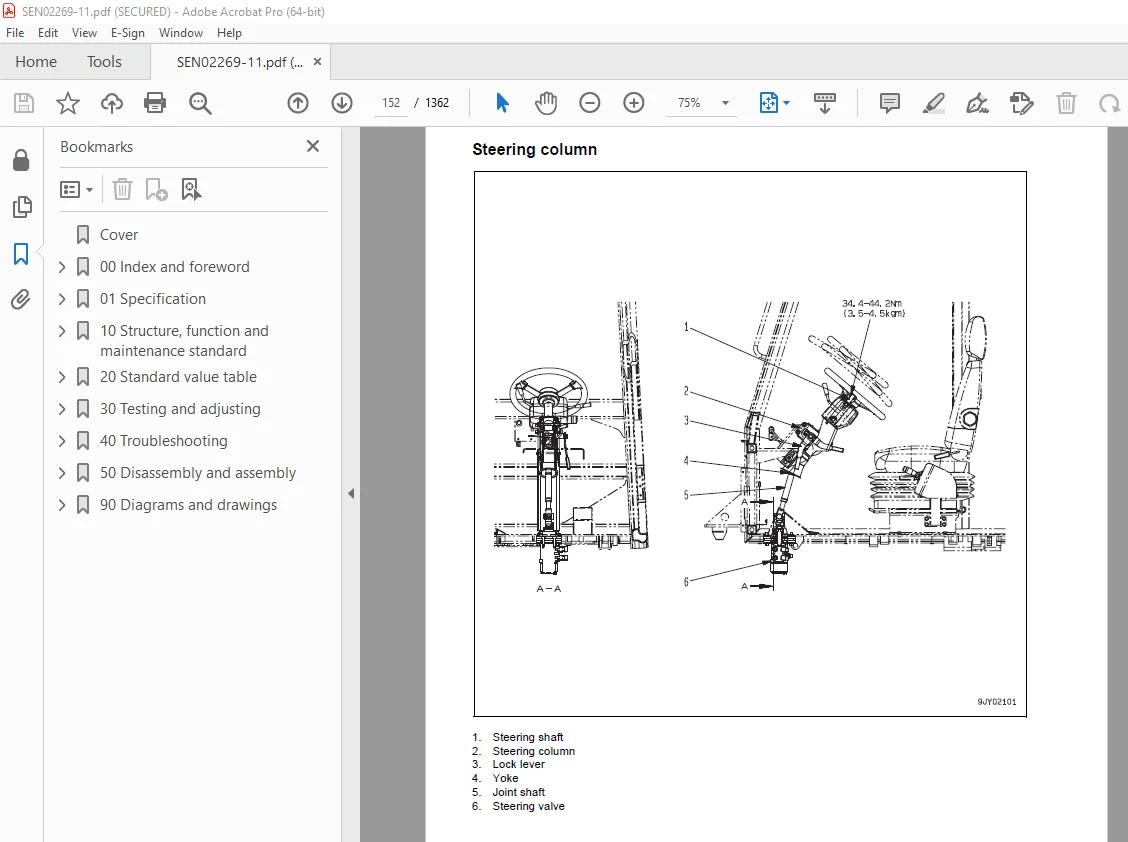
Steering system 151
Steering column 152
Brake system 155
Brake piping 156
Brake valve 158
Accumulator charge valve 161
Accumulator 165
Slack adjuster 166
Brake 168
Proportional reducing valve 173
Brake system tank 174
Parking brake 176
Parking brake solenoid 180
Undercarriage and frame 183
Suspension 184
Suspension cylinder 190
Oscillation hitch 192
Hydraulic system 197
Steering, hoist oil pressure piping diagram 198
Dump body control 199
Hydraulic tank and filter 200
Flow amp valve 201
Steering valve 204
Steering cylinder 208
Hoist valve 210
EPC valve 216
Hoist cylinder 217
Hydraulic pump 218
Cab and its attachments 221
ROPS cab 222
Cab tilt 223
Air conditioner 224
Rear view monitor 232
Controller related 235
Electrical system, Part 1 237
Machine monitor system 238
Electrical system, Part 2 259
Automatic shift control system 260
Retarder control system 292
Auto emergency steering system 304
Dump control lever 305
Electrical system, Part 3 311
Payload meter (Card type) 312
Electrical system, Part 4 345
Sensors, switches 346
KOMTRAX terminal system (If equipped) 354
20 Standard value table 357
Standard service value table 357
Standard value table for engine 358
Standard value table for chassis 359
30 Testing and adjusting 367
Testing and adjusting, Part 1 367
Precautions before work 369
Tools for testing, adjusting, and troubleshooting 370
Sketches of special tools 375
Measuring engine speed 376
Measuring intake air pressure (boost pressure) 377
Measuring exhaust temperature 378
Measuring exhaust gas color 380
Adjusting valve clearance 381
Measuring compression pressure 383
Measuring blow-by pressure 385
Measuring engine oil pressure 386
Handling of fuel system devices 387
Releasing residual pressure from fuel system 387
Testing fuel pressure 388
Testing fuel return and leak amount 389
Bleeding air from fuel circuit 392
Testing fuel circuit for leakage 394
Testing and adjusting alternator belt tension 395
Testing and adjusting air conditioner compressor belt tension 395
Adjusting the shims in the body mount 396
Testing and adjusting, Part 2 399
Measuring torque converter stall speed 401
Measuring power train oil pressure 402
Adjusting transmission speed sensor 410
Testing and adjusting brake oil pressure 412
Testing of accumulator nitrogen gas pressure and procedure for charging accumulator with nitrogen gas 416
Testing brake performance 424
Releasing remaining pressure in brake circuit 425
Bleeding air from brake circuit 426
Measuring wear of wheel brake disc 427
Measuring wear of parking brake pad 428
Method for emergency release of parking brake 430
Testing and adjusting steering circuit oil pressure 431
Testing and adjusting suspension cylinder 433
Method of tilting cab up 437
Testing and adjusting dump circuit oil pressure 439
Adjusting body positioner sensor 442
Procedure for adjusting length of spring in body heating spherical joint 443
Adjustment of tilt lock lever of steering wheel 444
Handling engine controller high voltage circuit 445
Adjusting transmission controller 445
Method for emergency escape at electrical system failure 446
Testing and adjusting, Part 3 451
Setting and adjusting various equipments 452
Special function of machine monitor (EMMS) 463
How to start operation of KOMTRAX terminal 497
Lamp display of KOMTRAX terminal 501
Pm Clinic check sheet 504
40 Troubleshooting 509
Failure code table and fuse locations 509
Failure code table 510
Before troubleshooting by failure codes 517
General information on troubleshooting 521
Precautions before work 522
Points to remember when performing troubleshooting 523
How to proceed in troubleshooting 525
Checks before troubleshooting 527
Classification and procedures of troubleshooting 528
Information in troubleshooting table 532
Troubleshooting method for disconnecting wiring harness of pressure sensor system 534
Connection table for connector pin numbers 537
T-branch box and T- branch adapter table 573
Troubleshooting by failure code (Display of code), Part 1 577
Failure code [1500L0] Detecting dual engagement 579
Failure code [15B0NX] Transmission oil filter: Clogging 580
Failure code [15F0KM] R o F gear shift abuse 1 582
Failure code [15F0MB] R o F gear shift abuse 2 582
Failure code [15F7KM] Transmission forward clutch abuse 583
Failure code [15G0MW] Reverse clutch system failure (Slip is detected) 584
Failure code [15G7KM] Transmission reverse clutch abuse 586
Failure code [15H0MW] Hi clutch system failure (Slip is detected) 588
Failure code [15J0MW] Lo clutch system failure (Slip is detected) 590
Failure code [15K0MW] 1st clutch system failure (Slip is detected) 592
Failure code [15L0MW] 2nd clutch system failure (Slip is detected) 594
Failure code [15M0MW] 3rd clutch system failure (Slip is detected) 596
Failure code [15SBL1] Reverse clutch pressure control valve failure 598
Failure code [15SBMA] Reverse clutch pressure control valve failure 601
Failure code [15SCL1] Hi clutch pressure control valve failure 602
Failure code [15SCMA] Hi clutch pressure control valve failure 605
Failure code [15SDL1] Lo clutch pressure control valve failure 606
Failure code [15SDMA] Lo clutch pressure control valve failure 609
Failure code [15SEL1] 1st clutch pressure control valve failure 610
Failure code [15SEMA] 1st clutch pressure control valve failure 613
Failure code [15SFL1] 2nd clutch pressure control valve failure 614
Failure code [15SFMA] 2nd clutch pressure control valve failure 617
Failure code [15SGL1] 3rd clutch pressure control valve failure 618
Failure code [15SGMA] 3rd clutch pressure control valve failure 621
Failure code [15SJMA] Lockup clutch pressure control valve failure 622
Failure code [15SKMA] Interaxle differential lock clutch pressure control valve failure 624
Failure code [2F00KM] Dragging of parking brake 626
Failure code [2G42ZG] Lowering of accumulator oil pressure (front) 628
Failure code [2G43ZG] Lowering of accumulator oil pressure (rear) 628
Troubleshooting by failure code (Display of code), Part 2 631
Failure code [989A00] Engine overrun prevention activated 633
Failure code [989D00] Rear section tipping over alarm (Raising operation on slope) 633
Failure code [AA10NX] Air cleaner clogging 634
Failure code [AB00MA] Battery charge circuit failure 636
Failure code [B@BAZG] Lowering of engine oil pressure 637
Failure code [B@BAZK] Lowering of engine oil level 638
Failure code [B@BCNS] Engine overheat 639
Failure code [B@BCZK] Lowering of coolant level 640
Failure code [B@C6NS] Overheat of brake cooling oil temperature (front) 642
Failure code [B@C8NS] Overheat of brake cooling oil temperature (center) 642
Failure code [B@CENS] Overheat of torque converter oil temperature 643
Failure code [B@HAZK] Hydraulic tank oil: Level too low 644
Failure code [B@JANS] Overheat of steering oil temperature 645
Failure code [CA111] Abnormality in engine controller 646
Failure code [CA115] Engine Ne or Bkup speed sensor error 648
Failure code [CA122] Charge (boost) pressure sensor high error 650
Failure code [CA123] Charge (boost) pressure sensor low error 652
Failure code [CA131] Throttle sensor high error 654
Failure code [CA132] Throttle sensor low error 656
Failure code [CA135] Engine oil pressure sensor high error 658
Failure code [CA141] Engine oil pressure sensor low error 660
Failure code [CA144] Coolant temperature sensor high error 662
Failure code [CA145] Coolant temperature sensor low error 664
Failure code [CA153] Charge (boost) temperature sensor high error 666
Failure code [CA154] Charge (boost) temperature sensor low error 668
Failure code [CA187] Sensor power supply 2 low error 670
Failure code [CA221] Atmospheric pressure sensor high error 672
Failure code [CA222] Atmospheric pressure sensor low error 674
Failure code [CA227] Sensor power supply 2 high error 676
Failure code [CA234] Engine overspeed 676
Failure code [CA238] Ne speed sensor power supply error 677
Failure code [CA263] Fuel Temperature Sensor High Error 678
Failure code [CA265] Fuel Temperature Sensor Low Error 680
Failure code [CA271] PCV1 Short circuit 682
Failure code [CA272] PCV1 Disconnection 683
Failure code [CA273] PCV2 Short circuit 684
Failure code [CA274] PCV2 Disconnection 685
Failure code [CA322] Injector #1 open/short error 686
Failure code [CA323] Injector #5 open/short error 688
Failure code [CA324] Injector #3 open/short error 690
Failure code [CA325] Injector #6 open/short error 692
Failure code [CA331] Injector #2 open/short error 694
Failure code [CA332] Injector #4 open/short error 696
Troubleshooting by failure code (Display of code), Part 3 699
Failure code [CA342] Calibration code inconsistency 702
Failure code [CA351] Injectors drive circuit error 703
Failure code [CA352] Sensor power supply 1 low error 704
Failure code [CA386] Sensor power supply 1 high error 706
Failure code [CA431] Idle validation switch error 707
Failure code [CA432] Idle validation action error 710
Failure code [CA441] Battery voltage low error 713
Failure code [CA442] Battery voltage high error 714
Failure code [CA449] Common rail pressure high error 2 715
Failure code [CA451] Common rail pressure sensor high error 716
Failure code [CA452] Common rail pressure sensor low error 718
Failure code [CA553] Common rail pressure high error 1 720
Failure code [CA554] Common rail pressure sensor in range error 721
Failure code [CA559] Supply pump pressure very low error 1 722
Failure code [CA689] Engine Ne speed sensor error 726
Failure code [CA731] Engine Bkup speed sensor phase error 728
Failure code [CA757] All continuous data lost error 729
Failure code [CA778] Engine Bkup speed sensor error 730
Failure code [CA1633] KOMNET datalink timeout error 732
Failure code [CA2185] Throttle sensor power supply voltage high error 734
Failure code [CA2186] Throttle sensor power supply voltage low error 736
Failure code [CA2249] Supply pump pressure very low error 2 738
Failure code [CA2555] Intake air heater relay open circuit error 740
Failure code [CA2556] Intake air heater relay short circuit error 742
Failure code [DAF9KM] (Machine monitor connector: Error in operation or setting) 744
Failure code [DAFRKR] Abnormal CAN communication (machine monitor): Abnormal communication 745
Failure code [DAQ0KK] (Transmission controller: Power source voltage too low) 746
Failure code [DAQ0KT] (Transmission nonvolatile memory: Abnormality in controller) 748
Failure code [DAQ2KK] (Transmission controller solenoid power source: Voltage too low) 749
Failure code [DAQRKR] Abnormal CAN communication (Transmission): Abnormal communication 750
Failure code [DAQRMA] (Transmission controller option setting: Malfunction) 755
Failure code [DB10KT] (Retarder controller nonvolatile memory: Abnormality in controller) 755
Failure code [DB12KK] (Retarder controller solenoid power source: Power source voltage too low) 756
Failure code [DB13KK] (Retarder controller battery direct power source: Power source voltage too low) 757
Failure code [DB19KQ] (Retarder controller model select signal: Inconsistent model selection signal) 758
Failure code [DB1QMA] (Retarder controller option setting: Malfunction) 759
Failure code [DB1RKR] CAN communication (retarder controller): Communication disabled 760
Failure code [DB2RKR] CAN communication (engine controller): Communication disabled 764
Failure code [DDTHKA] Fill switch for Hi clutch: Disconnection 769
Failure code [DDTJKA] Fill switch for Lo clutch: Disconnection 770
Failure code [DDTKKA] Fill switch for 1st clutch: Disconnection 771
Failure code [DDTLKA] Fill switch for 2nd clutch: Disconnection 772
Failure code [DDTMKA] Fill switch for 3rd clutch: Disconnection 773
Failure code [DDTNKA] Fill switch for R clutch: Disconnection 774
Failure code [DF10KA] Gear shift lever: Disconnection 775
Failure code [DF10KB] Gear shift lever: Short circuit 778
Troubleshooting by failure code (Display of code), Part 4 783
Failure code [DGF1KX] Transmission oil temperature sensor: Input signal out of range 786
Failure code [DGR3KZ] Center brake oil temperature sensor: Disconnection or short circuit 788
Failure code [DGR3L8] Center brake oil temperature sensor: Inconsistent analog signals 789
Failure code [DGR4KZ] Front brake oil temperature sensor: Disconnection or short circuit 790
Failure code [DGR4L8] Front brake oil temperature sensor: Inconsistent analog signals 791
Failure code [DGR6KX] Steering oil temperature sensor: Input signal out of range 792
Failure code [DGT1KX] Torque converter oil temperature sensor: Input signal out of range 794
Failure code [DHT5KX] Torque converter oil pressure sensor: Input signal out of range 796
Failure code [DHT5L6] Torque converter oil pressure sensor: Inconsistent signals during a travel and stop 798
Failure code [DHU2KX] Front accumulator oil pressure sensor: Input signal out of range 800
Failure code [DHU3KX] Rear accumulator oil pressure sensor: Input signal out of range 802
Failure code [DJF1KA] Fuel level sensor: Disconnection 804
Failure code [DK51L5] Retarder lever potentiometer: Potentiometer signal is inconsistent with switch signal 806
Failure code [DK52KX] Dump lever potentiometer failure 1: Input signal out of range 808
Failure code [DK53L8] Dump lever potentiometer failure 2: Inconsistent analog signal 810
Failure code [DK54KX] Body positioner sensor: Input signal out of range 812
Failure code [DKH0KX] Clinometer sensor signal out of range 814
Failure code [DLF1KA] Transmission input shaft speed sensor: Disconnection 816
Failure code [DLF1LC] Transmission input shaft speed sensor: Inconsistent rotation speed signal 818
Failure code [DLF2KA] Transmission intermediate shaft speed sensor: Disconnection 820
Failure code [DLF2LC] Transmission intermediate shaft speed sensor: Inconsistent speed signal 822
Failure code [DLF4KA] Differential speed sensor: Disconnection 824
Failure code [DLT3KA] Transmission output shaft speed sensor: Disconnection 826
Failure code [DV00KB] Alarm buzzer output: Short circuit 828
Failure code [DW72KZ] Kick-out solenoid output system: Disconnection or short circuit 830
Failure code [DW73KZ] Hoist switching valve output system: Disconnection or short circuit 832
Failure code [DW78KZ] Rear brake BCV command output system: Disconnection or short circuit 834
Failure code [DW79KZ] Front brake BCV command output system: Disconnection or short circuit 836
Failure code [DX11K4] Rear brake proportional pressure reducing solenoid valve: Out of control 838
Failure code [DX11KA] Rear brake proportional pressure reducing solenoid valve output circuit: Disconnection 840
Failure code [DX11KB] Rear brake proportional pressure reducing solenoid valve: Short circuit 842
Failure code [DX11KY] Rear brake proportional pressure reducing solenoid valve: Short circuit to power source line 844
Failure code [DX11MA] Rear brake proportional pressure reducing solenoid valve: Malfunction 845
Failure code [DX12K4] Front brake proportional pressure reducing solenoid valve: Out of control 846
Failure code [DX12KA] Front brake proportional pressure reducing solenoid valve output circuit: Disconnection 848
Failure code [DX12KB] Front brake proportional pressure reducing solenoid valve: Short circuit 850
Troubleshooting by failure code (Display of code), Part 5 853
Failure code [DX12KY] Front brake proportional pressure reducing solenoid valve: Short circuit to power source line 855
Failure code [DX12MA] Front brake proportional pressure reducing solenoid valve: Malfunction 856
Failure code [DX13KA] Hoist EPC valve output circuit: Disconnection 858
Failure code [DX13KB] Hoist EPC valve output circuit: Short circuit 860
Failure code [DX13KY] Hoist EPC valve output circuit: Short circuit in power source line 862
Failure code [DXH0KA] Disconnection in output circuit of interaxle differential lock clutch solenoid 863
Failure code [DXH0KB] Ground fault in output circuit of interaxle differential lock clutch solenoid 864
Failure code [DXH0KY] Hot short in output circuit of interaxle differential lock clutch solenoid 865
Failure code [DXH1KA] Lockup clutch solenoid output circuit: Disconnection 866
Failure code [DXH1KB] Lockup clutch solenoid output circuit: Short circuit 868
Failure code [DXH1KY] Lockup clutch solenoid output circuit: Short circuit to power source line 870
Failure code [DXH2KA] Hi clutch solenoid output circuit: Disconnection 872
Failure code [DXH2KB] Hi clutch solenoid output circuit: Short circuit 874
Failure code [DXH2KY] Hi clutch solenoid output circuit: Short circuit to power source line 876
Failure code [DXH3KA] Lo clutch solenoid output circuit: Disconnection 878
Failure code [DXH3KB] Lo clutch solenoid output circuit: Short circuit 880
Failure code [DXH3KY] Lo clutch solenoid output circuit: Short circuit in power source line 882
Failure code [DXH4KA] 1st clutch solenoid output circuit: Disconnection 884
Failure code [DXH4KB] 1st clutch solenoid output circuit: Short circuit 886
Failure code [DXH4KY] 1st clutch solenoid output circuit: Short circuit to power source line 888
Failure code [DXH5KA] 2nd clutch solenoid output circuit: Disconnection 890
Failure code [DXH5KB] 2nd clutch solenoid output circuit: Short circuit 892
Failure code [DXH5KY] 2nd clutch solenoid output circuit: Short circuit in power source line 894
Failure code [DXH6KA] 3rd clutch solenoid output circuit: Disconnection 896
Failure code [DXH6KB] 3rd clutch solenoid output circuit: Short circuit 898
Failure code [DXH6KY] 3rd clutch solenoid output circuit: Short circuit to power source line 900
Failure code [DXH7KA] R clutch solenoid output circuit: Disconnection 902
Failure code [DXH7KB] R clutch solenoid output circuit: Short circuit 904
Failure code [DXH7KY] R clutch solenoid output circuit: Short circuit to power source line 906
Troubleshooting of electrical system
(E-mode) 909
Before troubleshooting of electrical system 911
Contents of troubleshooting table 914
E-1 Engine does not start 915
E-2 Automatic preheating does not operate 918
E-3 Machine monitor does not display all, when starting switch is turned ON 922
E-4 Machine monitor does not operate when starting switch is OFF 924
E-5 Alarm buzzer does not sound 926
E-6 Gauges of machine monitor, caution lamps or character display section do not display properly 927
E-7 Selection of display in character display section cannot be changed 928
E-8 Power mode selecting function does not operate properly 932
E-9 AISS function does not operate properly 933
E-10 Seat belt caution lamp does not display properly 934
E-11 Turn signal lamp or turning lamp (hazard lamp) does not work properly 935
E-12 Night illumination (lighting) does not work properly 938
E-13 Emergency steering does not operate 945
E-14 Dump lever does not operate normally 950
E-15 KOMTRAX system does not operate normally 952
E-16 Electric priming pump does not operate or does not stop automatically 956
E-17 Air conditioner does not operate normally 958
Troubleshooting of hydraulic and
mechanical system (H-mode) 965
Contents of troubleshooting table 967
H-1 Machine does not start 968
H-2 Machine does not travel smoothly (machine jerks) 970
H-3 Lockup cannot be cancelled 970
H-4 Excessive shock when starting or shifting 971
H-5 Transmission does not shift up 972
H-6 Machine lacks power or speed when traveling 973
H-7 Time lag is excessive when starting or shifting gear 975
H-8 Torque converter oil temperature is high 976
H-9 Torque converter oil pressure is low 977
H-10 Front brake is ineffective 978
H-11 Center brake is ineffective 979
H-12 Steering wheel is heavy 980
H-13 Steering wheel does not work 981
H-14 Steering wheel vibrates 982
H-15 Dump body lifting speed is slow 983
H-16 Dump body does not work 984
H-17 Excessive hydraulic drift of dump body 985
Troubleshooting of engine (S-mode) 987
How to use a troubleshooting chart 989
S-1 Engine is hard to start 992
S-2 Engine does not start 993
S-3 Engine does not pick up smoothly 996
S-4 Engine stops during operations 997
S-5 Engine does not rotate smoothly 998
S-6 Engine lacks output (or lacks power) 999
S-7 Exhaust gas color is black (incomplete combustion) 1000
S-8 Oil consumption is excessive (or exhaust gas color is blue) 1001
S-9 Oil gets contaminated prematurely 1002
S-10 Fuel consumption is excessive 1003
S-11 Oil is in coolant (or coolant spurts back or coolant level goes down) 1004
S-12 Oil pressure drops 1005
S-13 Oil level rises (coolant or fuel mixes) 1006
S-14 Coolant temperature rises too high (overheat) 1007
S-15 Abnormal noise comes out 1008
S-16 Vibration is excessive 1009
S-17 Air cannot be bled from fuel circuit 1010
50 Disassembly and assembly 1013
General information on disassembly and assembly 1013
Precautions before work 1014
How to read this manual 1015
Coating materials list 1017
Special tool list 1020
Sketches of special tools 1025
Engine and cooling system (SAA6D125E-5) 1039
Removal and installation of fuel supply pump assembly 1040
Removal and installation of fuel injector assembly 1045
Removal and installation of cylinder head assembly 1050
Removal and installation of engine front seal 1062
Removal and installation of engine rear seal 1064
Removal and installation of engine assembly 1068
Removal and installation of radiator assembly 1076
Removal and installation of cooling assembly 1078
Removal and installation of output shaft assembly 1081
Disassembly and assembly of output shaft assembly 1086
Power train, Part 1 1091
Removal and installation of transmission and front differential assembly 1092
Disconnection and connection of front differential assembly and transmission assembly 1098
Disassembly and assembly of front differential assembly 1100
Disassembly and assembly of torque converter assembly 1115
Power train, Part 2 1123
Disassembly and assembly of transmission assembly 1124
Power train, Part 3 1167
Removal and installation of center differential assembly 1168
Disassembly and assembly of center differential assembly 1172
Removal and installation of rear differential assembly 1189
Disassembly and assembly of rear differential assembly 1191
Power train, Part 4 1207
Removal and installation of front final drive and brake assembly 1208
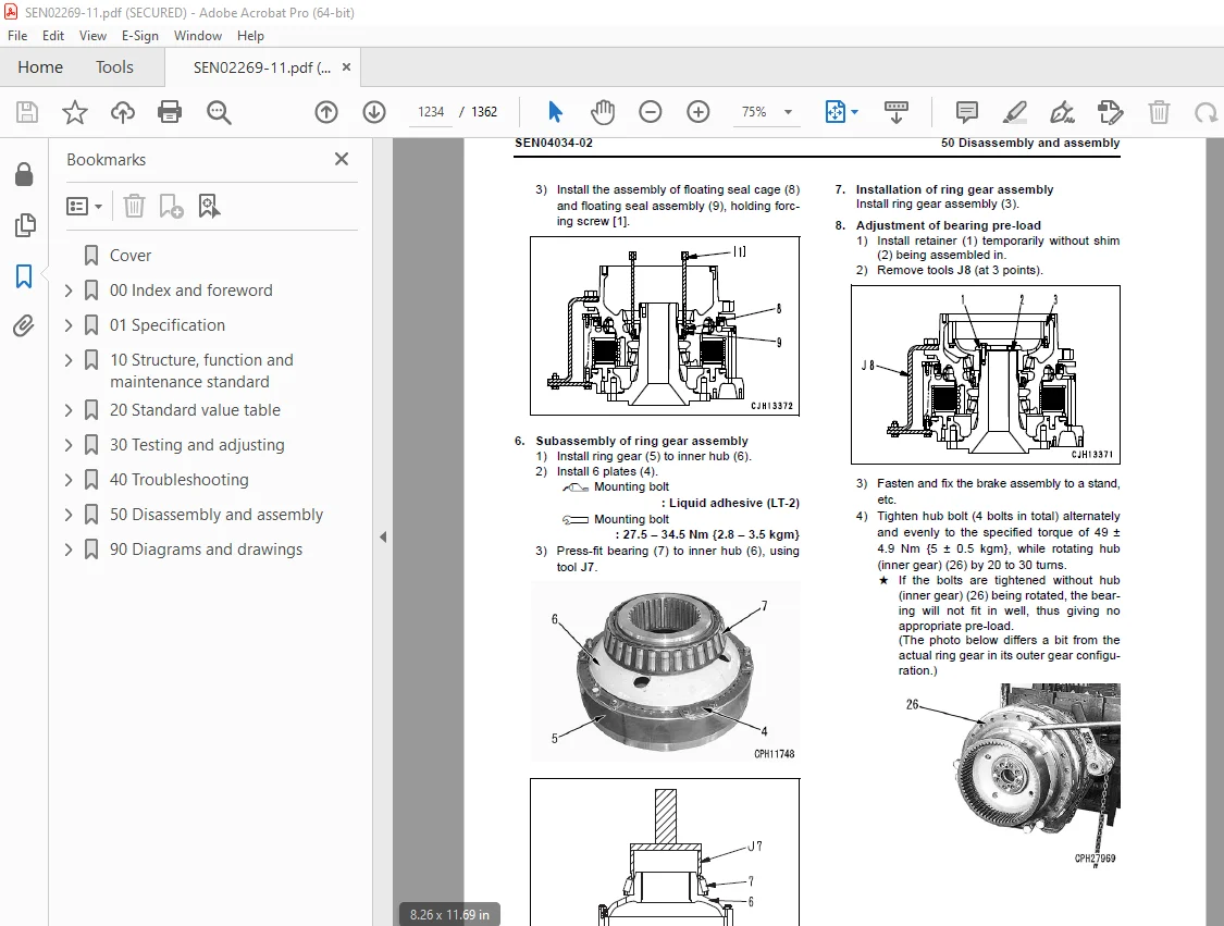
Disassembly and assembly of front final drive and brake assembly 1210
Removal and installation of center final drive and brake assembly 1224
Disassembly and assembly of center final drive and brake assembly 1226
Power train, Part 5 1237
Disassembly and assembly of rear final drive assembly 1238
Removal and installation of center axle assembly 1245
Removal and installation of rear axle assembly 1248
Undercarriage and frame 1251
Removal and installation of front suspension cylinder assembly 1252
Removal and installation of rear suspension cylinder assembly 1254
Removal and installation of equalizer bar 1255
Removal and installation of hitch frame assembly 1257
Disassembly and assembly of hitch frame assembly 1267
Hydraulic system 1275
Removal and installation of flow amp valve 1276
Removal and installation of hoist valve assembly 1278
Disassembly and assembly of steering cylinder assembly 1281
Disassembly and assembly of hoist cylinder assembly 1285
Body 1291
Removal and installation of body assembly 1292
Cab and its attachments 1295
Removal and installation of operator’s cab 1296
Removal and installation of operator’s cab glass (Stuck glass) 1301
Disassembly and assembly of operator’s seat assembly (If equipped) 1308
Electrical system 1319
Removal and installation of air conditioner unit assembly 1320
Removal and installation of engine controller 1325
Removal and installation of retarder controller 1327
Removal and installation of transmission controller assembly 1329
90 Diagrams and drawings 1331
Hydraulic diagrams and drawings 1331
Power train hydraulic circuit diagram 1333
Steering and hoist hydraulic circuit diagram 1335
Brake hydraulic circuit diagram 1337
Brake cooling hydraulic circuit diagram 1339
Electrical diagrams and drawings 1341
Electrical circuit diagram for inside cab (1/4) 1343
Electrical circuit diagram for inside cab (2/4) 1345
Electrical circuit diagram for inside cab (3/4) 1347
Electrical circuit diagram for inside cab (4/4) 1349
Electrical circuit diagram for outside cab (1/3) 1351
Electrical circuit diagram for outside cab (2/3) 1353
Electrical circuit diagram for outside cab (3/3) 1355
Electrical circuit diagram for payload meter 1357
Connectors table and arrangement drawing 1359
DESCRIPTION:
Komatsu HM300-2R Dump Truck Shop Manual SEN02269-11 – PDF DOWNLOAD
SERIAL NUMBERS 7001 and up
How to read the shop manual
1. Composition of shop manual
This shop manual contains the necessary technical information for services performed in a workshop.
For ease of understanding, the manual is divided into the following sections.
00. Index and foreword
This section explains the shop manuals list, table of contents, safety, and basic information.
01. Specification
This section explains the specifications of the machine.
10. Structure, function and maintenance standard
This section explains the structure, function, and maintenance standard values of each component.
The structure and function sub-section explains the structure and function of each component. It
serves not only to give an understanding of the structure, but also serves as reference material for
troubleshooting. The maintenance standard sub-section explains the criteria and remedies for disassembly
and service.
20. Standard value table
This section explains the standard values for new machine and judgement criteria for testing,
adjusting, and troubleshooting. This standard value table is used to check the standard values in
testing and adjusting and to judge parts in troubleshooting.
30. Testing and adjusting
This section explains measuring instruments and measuring methods for testing and adjusting, and
method of adjusting each part. The standard values and judgement criteria for testing and adjusting
are explained in Testing and adjusting.
40. Troubleshooting
This section explains how to find out failed parts and how to repair them. The troubleshooting is
divided by failure modes. The “S mode” of the troubleshooting related to the engine may be also
explained in the Chassis volume and Engine volume. In this case, see the Chassis volume.
50. Disassembly and assembly
This section explains the special tools and procedures for removing, installing, disassembling, and
assembling each component, as well as precautions for them. In addition, tightening torque and
quantity and weight of coating material, oil, grease, and coolant necessary for the work are also
explained.
90. Diagrams and drawings (chassis volume)/Repair and replacement of parts (engine volume)
q Chassis volume
This section gives hydraulic circuit diagrams and electrical circuit diagrams.
q Engine volume
This section explains the method of reproducing, repairing, and replacing parts.
S.V 29/12/24