Komatsu HM300-2 Dump Truck Shop Manual SEN00237-19 – PDF DOWNLOAD
$38.95
Komatsu HM300-2 Dump Truck Shop Manual SEN00237-19 – PDF DOWNLOAD
SERIAL NUMBERS 2001 and up
Description
Komatsu HM300-2 Dump Truck Shop Manual SEN00237-19 – PDF DOWNLOAD
FILE DETAILS:
Komatsu HM300-2 Dump Truck Shop Manual SEN00237-19 – PDF DOWNLOAD
Language : English
Pages : 1402
Downloadable : Yes
File Type : PDF
IMAGES PREVIEW OF THE MANUAL:
TABLE OF CONTENTS:
Komatsu HM300-2 Dump Truck Shop Manual SEN00237-19 – PDF DOWNLOAD
SERIAL NUMBERS 2001 and up
Cover 1
00 Index and foreword 3
Index 3
Composition of shop manual 4
Table of contents 6
Foreword and general information 17
Safety notice 18
How to read the shop manual 24
Explanation of terms for maintenance standard 26
Handling of electric equipment and hydraulic component 28
Handling of connectors newly used for engines 37
How to read electric wire code 40
Precautions when carrying out operation 43
Method of disassembling and connecting push-pull type coupler 46
Standard tightening torque table 49
Conversion table 53
01 Specification 59
Specification and technical data 59
Specification drawings 60
Specifications 61
Weight table 64
Fuel, coolant and lubricants 65
10 Structure, function and maintenance standard 69
Engine and cooling system 69
Radiator, oil cooler, aftercooler 70
Output shaft 71
Power train, Part 1 75
Power train skeleton 76
Torque converter and transmission hydraulic piping 78
Brake cooling oil control valve (BCV) 80
Power train pump 81
Torque converter 84
Transmission 90
Transmission control valve 118
ECMV 119
Main relief, torque converter relief valve 126
Power train, Part 2 129
Drive shaft 130
Axle 131
Differential 134
Limited slip differential 140
Final drive 144
Steering system 151
Steering column 152
Brake system 155
Brake piping 156
Brake valve 158
Accumulator charge valve 161
Accumulator 165
Slack adjuster 166
Brake 168
Proportional reducing valve 173
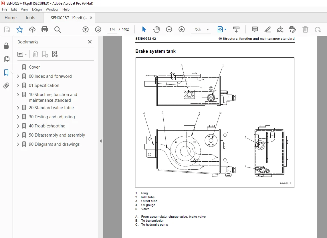
Brake system tank 174
Parking brake 176
Parking brake solenoid 180
Undercarriage and frame 183
Suspension 184
Suspension cylinder 190
Oscillation hitch 192
Hydraulic system 197
Steering, hoist oil pressure piping diagram 198
Dump body control 199
Hydraulic tank and filter 200
Flow amp valve 201
Steering valve 204
Steering cylinder 208
Hoist valve 210
Dump control valve (EPC valve) 216
Hoist cylinder 220
Hydraulic pump 221
Cab and its attachments 225
ROPS cab 226
Cab tilt 227
Air conditioner 228
Rear view monitor 236
Controller related 239
Electrical system, Part 1 241
Machine monitor system 242
Electrical system, Part 2 263
Automatic shift control system 264
Retarder control system 296
Auto emergency steering system 308
Battery disconnector switch 310
Dump control lever 306
Electrical system, Part 3 317
Payload meter (Card type) 318
Electrical system, Part 4 351
Sensors, switches 352
KOMTRAX terminal system (If equipped) 360
20 Standard value table 363
Standard service value table 363
Standard value table for engine 364
Standard value table for chassis 365
30 Testing and adjusting 371
Testing and adjusting, Part 1 371
Precautions before work 373
Tools for testing, adjusting, and troubleshooting 374
Sketches of special tools 379
Testing engine speed 380
Testing intake air pressure (boost pressure) 381
Testing exhaust temperature 382
Testing exhaust gas color 384
Adjusting valve clearance 385
Testing compression pressure 387
Testing blow-by pressure 389
Testing engine oil pressure 390
Testing EGR valve and bypass valve drive oil pressure 391
Handling of fuel system devices 392
Releasing residual pressure from fuel system 392
Testing fuel pressure 393
Handling during cylinder cut-out operation 394
Handling during no injection cranking operation 394
Testing fuel return and leak amount 395
Bleeding air from fuel circuit 398
Testing fuel circuit for leakage 399
Testing and adjusting alternator belt tension 400
Testing and adjusting air conditioner compressor belt tension 400
Adjusting the body mount 401
Testing and adjusting, Part 2 403
Testing torque converter stall speed 405
Testing power train oil pressure 406
Adjusting transmission speed sensor 414
Testing and adjusting brake oil pressure 416
Testing of accumulator nitrogen gas pressure and procedure for charging accumulator with nitrogen gas 420
Testing brake performance 428
Releasing remaining pressure in brake circuit 429
Bleeding air from brake circuit 430
Testing wear of wheel brake disc 431
Testing wear of parking brake pad 432
Method for emergency release of parking brake 434
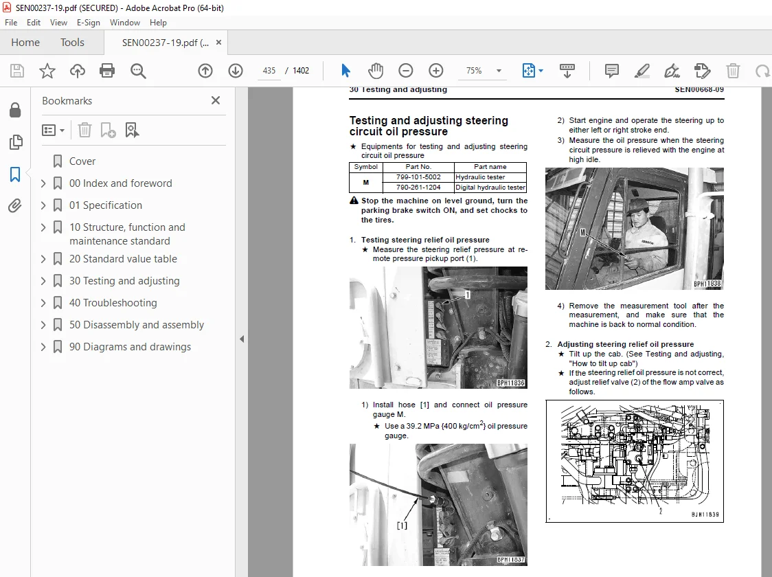
Testing and adjusting steering circuit oil pressure 435
Testing and adjusting suspension cylinder 437
Method of tilting cab up 441
Testing and adjusting dump circuit oil pressure 443
Adjusting body positioner sensor 446
Procedure for adjusting length of spring in body heating spherical joint 447
Adjustment of tilt lock lever of steering wheel 448
Handling engine controller high voltage circuit 449
Adjusting transmission controller 449
Method for emergency escape at electrical system failure 450
Testing and adjusting, Part 3 455
Setting and adjusting various equipments 456
Special function of machine monitor (EMMS) 468
How to start operation of KOMTRAX terminal 505
Lamp display of KOMTRAX terminal 510
Pm Clinic check sheet 513
40 Troubleshooting 517
Failure code table and fuse locations 517
Failure codes table 518
Fuse locations 526
General Information on troubleshooting 533
Precautions before work 534
Points to remember when performing troubleshooting 535
How to proceed in troubleshooting 537
Checks before troubleshooting 539
Classification and procedures of troubleshooting 540
Information in troubleshooting table 544
Troubleshooting method for disconnecting wiring harness of pressure sensor system 546
Connection table for connector pin numbers 549
T-branch box and T-branch adapter table 585
Troubleshooting by failure code, Part 1 589
Failure code [1500L0] Detecting dual engagement 591
Failure code [15B0NX] Transmission oil filter: Clogging 592
Failure code [15F0KM] R o F gear shift abuse 1 594
Failure code [15F0MB] R o F gear shift abuse 2 594
Failure code [15F7KM] Transmission forward clutch abuse 595
Failure code [15G0MW] Reverse clutch system failure (Slip is detected) 596
Failure code [15G7KM] Transmission reverse clutch abuse 598
Failure code [15H0MW] Hi clutch system failure (Slip is detected) 600
Failure code [15J0MW] Lo clutch system failure (Slip is detected) 602
Failure code [15K0MW] 1st clutch system failure (Slip is detected) 604
Failure code [15L0MW] 2nd clutch system failure (Slip is detected) 606
Failure code [15M0MW] 3rd clutch system failure (Slip is detected) 608
Failure code [15SBL1] Reverse clutch pressure control valve failure 610
Failure code [15SBMA] Reverse clutch pressure control valve failure 613
Failure code [15SCL1] Hi clutch pressure control valve failure 614
Failure code [15SCMA] Hi clutch pressure control valve failure 617
Failure code [15SDL1] Lo clutch pressure control valve failure 618
Failure code [15SDMA] Lo clutch pressure control valve failure 621
Failure code [15SEL1] 1st clutch pressure control valve failure 622
Failure code [15SEMA] 1st clutch pressure control valve failure 625
Failure code [15SFL1] 2nd clutch pressure control valve failure 626
Failure code [15SFMA] 2nd clutch pressure control valve failure 629
Failure code [15SGL1] 3rd clutch pressure control valve failure 630
Failure code [15SGMA] 3rd clutch pressure control valve failure 633
Failure code [15SJMA] Lockup clutch pressure control valve failure 634
Failure code [15SKMA] Interaxle differential lock clutch pressure control valve failure 636
Failure code [2F00KM] Dragging of parking brake 638
Failure code [2G42ZG] Lowering of accumulator oil pressure (front) 640
Failure code [2G43ZG] Lowering of accumulator oil pressure (rear) 640
Failure code [989A00] Engine overrun prevention activated 641
Failure code [989D00] Rear section tipping over alarm (Raising operation on slope) 641
Failure code [AA10NX] Air cleaner clogging 642
Failure code [AB00MA] Battery charge circuit failure 644
Failure code [B@BAZG] Lowering of engine oil pressure 645
Failure code [B@BAZK] Lowering of engine oil level 646
Failure code [B@BCNS] Engine overheat 647
Failure code [B@BCZK] Lowering of coolant level 648
Failure code [B@C6NS] Overheat of brake cooling oil temperature (front) 650
Failure code [B@C8NS] Overheat of brake cooling oil temperature (center) 650
Failure code [B@CENS] Overheat of torque converter oil temperature 651
Failure code [B@HAZK] (Hydraulic tank oil: Level too low) 652
Failure code [B@JANS] Overheat of steering oil temperature 653
Troubleshooting by failure code, Part 2 655
Failure code [CA111] Abnormality in engine controller 658
Failure code [CA115] Engine Ne or Bkup speed sensor error 660
Failure code [CA122] Charge (boost) pressure sensor high error 662
Failure code [CA123] Charge (boost) pressure sensor low error 664
Failure code [CA131] Throttle sensor high error 666
Failure code [CA132] Throttle sensor low error 669
Failure code [CA135] Engine oil pressure sensor high error 672
Failure code [CA141] Engine oil pressure sensor low error 674
Failure code [CA144] Coolant temperature sensor high error 676
Failure code [CA145] Coolant temperature sensor low error 678
Failure code [CA153] Charge (boost) temperature sensor high error 680
Failure code [CA154] Charge (boost) temperature sensor low error 682
Failure code [CA187] Sensor power supply 2 low error 684
Failure code [CA221] Atmospheric pressure sensor high error 686
Failure code [CA222] Atmospheric pressure sensor low error 688
Failure code [CA227] Sensor power supply 2 high error 690
Failure code [CA234] Engine overspeed 691
Failure code [CA238] Ne speed sensor power supply error 692
Failure code [CA263] Fuel Temperature Sensor High Error 694
Failure code [CA265] Fuel Temperature Sensor Low Error 696
Failure code [CA271] PCV1 Short circuit 698
Failure code [CA272] PCV1 Disconnection 699
Failure code [CA273] PCV2 Short circuit 700
Failure code [CA274] PCV2 Disconnection 701
Failure code [CA322] Injector #1 open/short error 702
Failure code [CA323] Injector #5 open/short error 704
Failure code [CA324] Injector #3 open/short error 706
Failure code [CA325] Injector #6 open/short error 708
Failure code [CA331] Injector #2 open/short error 710
Failure code [CA332] Injector #4 open/short error 712
Failure code [CA342] Calibration code inconsistency 714
Failure code [CA351] Injectors drive circuit error 715
Failure code [CA352] Sensor power supply 1 low error 716
Failure code [CA386] Sensor power supply 1 high error 718
Failure code [CA431] Idle validation switch error 720
Failure code [CA432] Idle validation action error 723
Failure code [CA441] Battery voltage low error 726
Failure code [CA442] Battery voltage high error 727
Failure code [CA449] Common rail pressure high error 2 728
Failure code [CA451] Common rail pressure sensor high error 730
Failure code [CA452] Common rail pressure sensor low error 732
Failure code [CA553] Common rail pressure high error 1 734
Failure code [CA554] Common rail pressure sensor in range error 735
Failure code [CA559] Supply pump pressure very low error 1 736
Failure code [CA689] Engine Ne speed sensor error 740
Failure code [CA731] Engine Bkup speed sensor phase error 742
Failure code [CA757] All continuous data lost error 743
Failure code [CA778] Engine Bkup speed sensor error 744
Failure code [CA1117] Loss of partial engine controller data 746
Failure code [CA1228] EGR valve servo error 1 747
Failure code [CA1625] EGR valve servo error 2 748
Failure code [CA1626] Bypass valve solenoid current high error 750
Failure code [CA1627] Bypass valve solenoid current low error 752
Failure code [CA1628] Bypass Valve Servo Error 1 754
Failure code [CA1629] Bypass Valve Servo Error 2 755
Troubleshooting by failure code, Part 3 757
Failure code [CA1631] Bypass valve lift sensor high error 760
Failure code [CA1632] Bypass valve lift sensor low error 762
Failure code [CA1633] KOMNET datalink timeout error 764
Failure code [CA1642] EGR inlet pressure sensor low error 766
Failure code [CA1653] EGR inlet pressure sensor high error 768
Failure code [CA2185] Throttle sensor supply voltage high error 770
Failure code [CA2186] Throttle sensor power supply low error 772
Failure code [CA2249] Supply pump pressure very low error 2 774
Failure code [CA2271] EGR valve lift sensor high error 776
Failure code [CA2272] EGR valve lift sensor low error 778
Failure code [CA2351] EGR valve solenoid operation short circuit 780
Failure code [CA2352] EGR valve solenoid operation disconnect 782
Failure code [CA2555] Intake air heater relay open circuit error 784
Failure code [CA2556] Intake air heater relay short circuit error 786
Failure code [DAF9KM] Machine monitor connector: Error in operation or setting 788
Failure code [DAFRKR] Abnormal CAN communication (machine monitor): Abnormal communication 789
Failure code [DAQ0KK] Transmission controller: Power source voltage too low 790
Failure code [DAQ0KT] Transmission nonvolatile memory: Abnormality in controller 792
Failure code [DAQ2KK] Transmission controller solenoid power source: Voltage too low 793
Failure code [DAQRKR] Abnormal CAN communication (Transmission): Abnormal communication 794
Failure code [DAQRMA] Transmission controller option setting: Malfunction 799
Failure code [DB10KT] Retarder controller nonvolatile memory: Abnormality in controller 799
Failure code [DB12KK] Retarder controller solenoid power source: Power source voltage too low 800
Failure code [DB13KK] Retarder controller battery direct power source: Power source voltage too low 801
Failure code [DB19KQ] Retarder controller model select signal: Inconsistent model selection signal 802
Failure code [DB1QMA] Retarder controller option setting: Malfunction 802
Failure code [DB1RKR] CAN communication (retarder controller): Communication disabled 803
Failure code [DB2RKR] CAN communication (engine controller): Communication disabled 807
Failure code [DD1ML4] Disagreement of accelerator-linked retarder switch signal 812
Failure code [DDTHKA] Fill switch for Hi clutch: Disconnection 814
Failure code [DDTJKA] Fill switch for Lo clutch: Disconnection 815
Failure code [DDTKKA] Fill switch for 1st clutch: Disconnection 816
Failure code [DDTLKA] Fill switch for 2nd clutch: Disconnection 817
Failure code [DDTMKA] Fill switch for 3rd clutch: Disconnection 818
Failure code [DDTNKA] Fill switch for R clutch: Disconnection 819
Failure code [DF10KA] Gear shift lever: Disconnection 820
Failure code [DF10KB] Gear shift lever: Short circuit 823
Failure code [DGF1KX] Transmission oil temperature sensor: Input signal out of range 826
Failure code [DGR3KZ] Center brake oil temperature sensor: Disconnection or short circuit 828
Failure code [DGR3L8] Center brake oil temperature sensor: Inconsistent analog signals 829
Failure code [DGR4KZ] Front brake oil temperature sensor: Disconnection or short circuit 830
Failure code [DGR4L8] Front brake oil temperature sensor: Inconsistent analog signals 831
Failure code [DGR6KX] Steering oil temperature sensor: Input signal out of range 832
Failure code [DGT1KX] Torque converter oil temperature sensor: Input signal out of range 834
Failure code [DHT5KX] Torque converter oil pressure sensor: Input signal out of range 836
Failure code [DHT5L6] Torque converter oil pressure sensor: Inconsistent signals during a travel and stop 838
Failure code [DHU2KX] Front accumulator oil pressure sensor: Input signal out of range 840
Failure code [DHU3KX] Rear accumulator oil pressure sensor: Input signal out of range 842
Failure code [DJF1KA] Fuel level sensor: Disconnection 844
Failure code [DK51L5] (Retarder lever potentiometer : Potentiometer signal is inconsistent with switch signal) 846
Failure code [DK52KX] Dump lever potentiometer failure 1: Input signal out of range 848
Failure code [DK53L8] Dump lever potentiometer failure 2: Inconsistent analog signal 850
Failure code [DK54KX] Body positioner sensor: Input signal out of range 852
Troubleshooting by failure code, Part 4 855
Failure code [DKH0KX] Clinometer sensor signal out of range 858
Failure code [DLF1KA] Transmission input shaft speed sensor: Disconnection 860
Failure code [DLF1LC] Transmission input shaft speed sensor: Inconsistent rotation speed signal 862
Failure code [DLF2KA] Transmission intermediate shaft speed sensor: Disconnection 864
Failure code [DLF2LC] Transmission intermediate shaft speed sensor: Inconsistent speed signal 866
Failure code [DLF4KA] Differential speed sensor: Disconnection 868
Failure code [DLT3KA] Transmission output shaft speed sensor: Disconnection 870
Failure code [DV00KB] Alarm buzzer output: Short circuit 872
Failure code [DW72KZ] Kick-out solenoid output system: Disconnection or short circuit 874
Failure code [DW73KZ] Hoist switching valve output system: Disconnection or short circuit 876
Failure code [DW78KZ] Rear brake BCV command output system: Disconnection or short circuit 878
Failure code [DW79KZ] Front brake BCV command output system: Disconnection or short circuit 880
Failure code [DX11K4] Rear brake proportional pressure reducing solenoid valve: Out of control 882
Failure code [DX11KA] Rear brake proportional pressure reducing solenoid valve output circuit: Disconnection 884
Failure code [DX11KB] Rear brake proportional pressure reducing solenoid valve: Short circuit 886
Failure code [DX11KY] Rear brake proportional pressure reducing solenoid valve: Short circuit to power source line 888
Failure code [DX11MA] Rear brake proportional pressure reducing solenoid valve: Malfunction 889
Failure code [DX12K4] Front brake proportional pressure reducing solenoid valve: Out of control 890
Failure code [DX12KA] Front brake proportional pressure reducing solenoid valve output circuit: Disconnection 892
Failure code [DX12KB] Front brake proportional pressure reducing solenoid valve: Short circuit 894
Failure code [DX12KY] Front brake proportional pressure reducing solenoid valve: Short circuit to power source line 896
Failure code [DX12MA] Front brake proportional pressure reducing solenoid valve: Malfunction 897
Failure code [DX13KA] Hoist EPC valve output circuit: Disconnection 898
Failure code [DX13KB] Hoist EPC valve output circuit: Short circuit 900
Failure code [DX13KY] Hoist EPC valve output circuit: Short circuit in power source line 902
Failure code [DXH0KA] Disconnection in output circuit of interaxle differential lock clutch solenoid 903
Failure code [DXH0KB] Ground fault in output circuit of interaxle differential lock clutch solenoid 904
Failure code [DXH0KY] Hot short in output circuit of interaxle differential lock clutch solenoid 905
Failure code [DXH1KA] Lockup clutch solenoid output circuit: Disconnection 906
Failure code [DXH1KB] Lockup clutch solenoid output circuit: Short circuit 908
Failure code [DXH1KY] Lockup clutch solenoid output circuit: Short circuit to power source line 910
Failure code [DXH2KA] Hi clutch solenoid output circuit: Disconnection 912
Failure code [DXH2KB] Hi clutch solenoid output circuit: Short circuit 914
Failure code [DXH2KY] Hi clutch solenoid output circuit: Short circuit to power source line 916
Failure code [DXH3KA] Lo clutch solenoid output circuit: Disconnection 918
Failure code [DXH3KB] Lo clutch solenoid output circuit: Short circuit 920
Failure code [DXH3KY] Lo clutch solenoid output circuit: Short circuit in power source line 922
Failure code [DXH4KA] 1st clutch solenoid output circuit: Disconnection 924
Failure code [DXH4KB] 1st clutch solenoid output circuit: Short circuit 926
Failure code [DXH4KY] 1st clutch solenoid output circuit: Short circuit to power source line 928
Failure code [DXH5KA] 2nd clutch solenoid output circuit: Disconnection 930
Failure code [DXH5KB] 2nd clutch solenoid output circuit: Short circuit 932
Failure code [DXH5KY] 2nd clutch solenoid output circuit: Short circuit in power source line 934
Failure code [DXH6KA] 3rd clutch solenoid output circuit: Disconnection 936
Failure code [DXH6KB] 3rd clutch solenoid output circuit: Short circuit 938
Failure code [DXH6KY] 3rd clutch solenoid output circuit: Short circuit to power source line 940
Failure code [DXH7KA] R clutch solenoid output circuit: Disconnection 942
Failure code [DXH7KB] R clutch solenoid output circuit: Short circuit 944
Failure code [DXH7KY] R clutch solenoid output circuit: Short circuit to power source line 946
Troubleshooting of electrical system (E-mode) 949
Information in troubleshooting table 950
E-1 Engine does not start 951
E-2 Automatic preheating does not operate 954
E-3 Machine monitor does not display all, when starting switch is turned ON 957
E-4 Machine monitor does not operate when starting switch is OFF 959
E-5 Alarm buzzer does not stop sounding 961
E-6 Gauges of machine monitor, caution lamps or character display section do not display properly 962
E-7 Selection of display in character display section cannot be changed 963
E-8 Power mode selecting function does not operate properly 967
E-9 AISS function does not operate properly 968
E-10 Seat belt caution lamp does not display properly 969
E-11 Turn signal lamp or turning lamp (hazard lamp) does not work properly 970
E-12 Night illumination (lighting) does not work properly 973
E-13 Emergency steering does not operate 980
E-14 Air conditioner does not operate normally 984
Troubleshooting of hydraulic and mechanical system (H-mode) 991
Contents of troubleshooting table 993
H-1 Machine does not start 994
H-2 Machine does not travel smoothly (machine jerks) 996
H-3 Lockup cannot be cancelled 996
H-4 Excessive shock when starting or shifting 997
H-5 Transmission does not shift up 998
H-6 Machine lacks power or speed when traveling 999
H-7 Time lag is excessive when starting or shifting gear 1001
H-8 Torque converter oil temperature is high 1002
H-9 Torque converter oil pressure is low 1003
H-10 Front brake is ineffective 1004
H-11 Center brake is ineffective 1005
H-12 Steering wheel is heavy 1006
H-13 Steering wheel does not work 1007
H-14 Steering wheel vibrates 1008
H-15 Dump body lifting speed is slow 1009
H-16 Dump body does not work 1010
H-17 Excessive hydraulic drift of dump body 1011
Troubleshooting of engine (S-mode) 1013
How to use a troubleshooting chart 1015
S-1 Engine is hard to start 1018
S-2 Engine does not start 1020
S-3 Engine does not pick up smoothly 1024
S-4 Engine stops during operations 1025
S-5 Engine does not rotate smoothly 1026
S-6 Engine lacks output (or lacks power) 1027
S-7 Exhaust gas color is black (incomplete combustion) 1028
S-8 Oil consumption is excessive (or exhaust gas color is blue) 1030
S-9 Oil gets contaminated prematurely 1031
S-10 Fuel consumption is excessive 1032
S-11 Oil is in coolant (or coolant spurts back or coolant level goes down) 1033
S-12 Oil pressure drops 1034
S-13 Oil level rises (coolant or fuel mixes) 1036
S-14 Coolant temperature rises too high (overheat) 1038
S-15 Abnormal noise comes out 1039
S-16 Vibration is excessive 1040
50 Disassembly and assembly 1043
General information on disassembly and assembly 1043
Precautions before work 1044
How to read this manual 1045
Coating materials list 1047
Special tool list 1050
Sketches of special tools 1054
Engine and cooling system, Part 1 1069
Removal and installation of fuel supply pump assembly 1070
Removal and installation of fuel injector assembly 1075
Removal and installation of cylinder head assembly 1080
Removal and installation of engine front seal 1093
Removal and installation of engine rear seal 1095
Engine and cooling system, Part 2 1101
Removal and installation of engine assembly 1102
Removal and installation of radiator assembly 1110
Removal and installation of cooling assembly 1112
Removal and installation of output shaft assembly 1115
Disassembly and assembly of output shaft assembly 1120
Power train, Part 1 1125
Removal and installation of transmission and front differential assembly 1126
Disconnection and connection of front differential assembly and transmission assembly 1132
Disassembly and assembly of front differential assembly 1134
Disassembly and assembly of torque converter assembly 1149
Power train, Part 2 1157
Disassembly and assembly of transmission assembly 1158
Power train, Part 3 1201
Removal and installation of center differential assembly 1202
Disassembly and assembly of center differential assembly 1206
Removal and installation of rear differential assembly 1223
Disassembly and assembly of rear differential assembly 1225
Power train, Part 4 1241
Removal and installation of front final drive and brake assembly 1242
Disassembly and assembly of front final drive and brake assembly 1244
Removal and installation of center final drive and brake assembly 1258
Disassembly and assembly of center final drive and brake assembly 1260
Power train, Part 5 1271
Disassembly and assembly of rear final drive assembly 1272
Removal and installation of center axle assembly 1279
Removal and installation of rear axle assembly 1282
Undercarriage and frame 1285
Removal and installation of front suspension cylinder assembly 1286
Removal and installation of rear suspension cylinder assembly 1288
Disassembly and assembly of front and rear suspension cylinder assembly 1289
Removal and installation of equalizer bar 1291
Removal and installation of hitch frame assembly 1293
Disassembly and assembly of hitch frame assembly 1303
Hydraulic system 1311
Removal and installation of flow amp valve 1312
Removal and installation of hoist valve assembly 1314
Disassembly and assembly of steering cylinder assembly 1317
Disassembly and assembly of hoist cylinder assembly 1321
Body 1327
Removal and installation of body assembly 1328
Cab and its attachments 1331
Removal and installation of operator’s cab 1332
Removal and installation of operator’s cab glass (Stuck glass) 1337
Disassembly and assembly of operator’s seat assembly (If equipped) 1344
Electrical system 1355
Removal and installation of air conditioner unit assembly 1356
Removal and installation of engine controller 1361
Removal and installation of retarder controller 1363
Removal and installation of transmission controller assembly 1365
90 Diagrams and drawings 1367
Hydraulic diagrams and drawings 1367
Power train hydraulic circuit diagram 1369
Steering and hoist hydraulic circuit diagram 1371
Brake hydraulic circuit diagram 1373
Brake cooling hydraulic circuit diagram 1375
Electrical diagrams and drawings 1377
Electrical circuit diagram for inside cab (2/4) (Serial No : 2001 – 2241) 1381
Electrical circuit diagram for inside cab (1/4) 1379
Electrical circuit diagram for inside cab (3/4) (Serial No : 2001 – 2241) 1385
Electrical circuit diagram for inside cab (4/4) 1389
Electrical circuit diagram for outside cab (1/3) 1391
Electrical circuit diagram for outside cab (2/3) 1393
Electrical circuit diagram for outside cab (3/3) 1395
Electrical circuit diagram for inside cab (2/4) (Serial No : 2242 and up) 1383
Electrical circuit diagram for inside cab (3/4) (Serial No : 2242 and up) 1387
Electrical circuit diagram for payload meter 1397
Connectors table and arrangement drawing 1399
DESCRIPTION:
Komatsu HM300-2 Dump Truck Shop Manual SEN00237-19 – PDF DOWNLOAD
SERIAL NUMBERS 2001 and up
How to read the shop manual 1
1. Composition of shop manual
This shop manual contains the necessary technical information for services performed in a workshop.
For ease of understanding, the manual is divided into the following sections.
00. Index and foreword
This section explains the shop manuals list, table of contents, safety, and basic information.
01. Specification
This section explains the specifications of the machine.
10. Structure, function and maintenance standard
This section explains the structure, function, and maintenance standard values of each component.
The structure and function sub-section explains the structure and function of each component. It
serves not only to give an understanding of the structure, but also serves as reference material for
troubleshooting. The maintenance standard sub-section explains the criteria and remedies for disassembly
and service.
20. Standard value table
This section explains the standard values for new machine and judgement criteria for testing,
adjusting, and troubleshooting. This standard value table is used to check the standard values in
testing and adjusting and to judge parts in troubleshooting.
30. Testing and adjusting
This section explains measuring instruments and measuring methods for testing and adjusting, and
method of adjusting each part. The standard values and judgement criteria for testing and adjusting
are explained in Testing and adjusting.
40. Troubleshooting
This section explains how to find out failed parts and how to repair them. The troubleshooting is
divided by failure modes. The “S mode” of the troubleshooting related to the engine may be also
explained in the Chassis volume and Engine volume. In this case, see the Chassis volume.
50. Disassembly and assembly
This section explains the special tools and procedures for removing, installing, disassembling, and
assembling each component, as well as precautions for them. In addition, tightening torque and
quantity and weight of coating material, oil, grease, and coolant necessary for the work are also
explained.
90. Diagrams and drawings (chassis volume)/Repair and replacement of parts (engine volume)
q Chassis volume
This section gives hydraulic circuit diagrams and electrical circuit diagrams.
q Engine volume
This section explains the method of reproducing, repairing, and replacing parts.
S.V 29/12/24


