Komatsu HM250-2 Dump Truck Shop Manual SEN04733-10 PDF
$38.95
Komatsu HM250-2 Dump Truck Shop Manual SEN04733-10 – PDF DOWNLOAD
SERIAL NUMBERS 2001 and up
Description
Komatsu HM250-2 Dump Truck Shop Manual SEN04733-10 – PDF DOWNLOAD
FILE DETAILS:
Komatsu HM250-2 Dump Truck Shop Manual SEN04733-10 – PDF DOWNLOAD
Language : English
Pages : 1506
Downloadable : Yes
File Type : PDF
IMAGES PREVIEW OF THE MANUAL:
TABLE OF CONTENTS:
Komatsu HM250-2 Dump Truck Shop Manual SEN04733-10 – PDF DOWNLOAD
SERIAL NUMBERS 2001 and up
Cover 1
00 Index and foreword 3
100 Index 3
Composition of shop manual 4
Table of contents 6
200 Foreword and general information 19
Safety notice 20
How to read the shop manual 26
Explanation of terms for maintenance standard 28
Handling of electric equipment and hydraulic component 30
Handling of connectors newly used for engines 39
How to read electric wire code 42
Precautions when carrying out operation 45
Method of disassembling and connecting push-pull type coupler 48
Standard tightening torque table 51
Conversion table 55
01 Specification 61
100 Specification and technical data 61
Specification drawings 62
Specifications 63
Weight table 66
Fuel, coolant and lubricants 67
10 Structure, function and
maintenance standard 71
100 Engine and cooling system 71
Radiator, oil cooler, aftercooler 72
Output shaft 73
201 Power train, Part 1 77
Power train skeleton 78
Torque converter and transmission hydraulic piping 80
Brake cooling oil control valve (BCV) 82
Power train pump 83
Torque converter 86
Transmission 92
Transmission control valve 120
ECMV 122
Main relief, torque converter relief valve 129
202 Power train, Part 2 133
Drive shaft 134
Axle 135
Differential 138
Limited slip differential 144
Final drive 148
300 Steering system 155
Steering column 156
400 Brake system 159
Brake piping 160
Brake valve 162
Accumulator charge valve 165
Accumulator 169
Slack adjuster 170
Brake 172
Proportional reducing valve 177
Brake system tank 178
Parking brake 180
Parking brake solenoid 184
500 Undercarriage and frame 187
Suspension 188
Suspension cylinder 194
Oscillation hitch 196
600 Hydraulic system 201
Steering, hoist oil pressure piping diagram 202
Dump body control 203
Hydraulic tank and filter 204
Flow amp valve 205
Steering valve 208
Steering cylinder 212
Hoist valve 214
EPC valve 220
Hoist cylinder 222
Hydraulic pump 223
700 Cab and its attachments 227
ROPS cab 228
Cab tilt 229
Rear view monitor 230
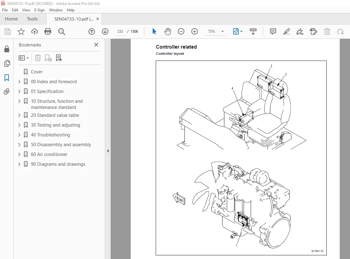
Controller related 233
801 Electrical system, Part 1 235
Machine monitor system 236
802 Electrical system, Part 2 257
Automatic shift control system 258
Retarder control system 290
Auto emergency steering system 302
Battery disconnector switch 304
Dump control lever 306
803 Electrical system, Part 3 311
Sensors, switches 312
KOMTRAX terminal system (If equipped) 320
20 Standard value table 323
100 Standard service value table 323
Standard value table for engine 324
Standard value table for chassis 325
30 Testing and adjusting 331
101 Testing and adjusting, Part 1 331
Precautions before work 333
Tools for testing, adjusting, and troubleshooting 334
Testing engine speed 337
Testing intake air pressure (boost pressure) 338
Testing exhaust temperature 339
Testing exhaust gas color 341
Adjusting valve clearance 342
Testing compression pressure 344
Testing blow-by pressure 346
Testing engine oil pressure 347
Testing EGR valve and bypass valve drive oil pressure 348
Handling of fuel system devices 349
Testing fuel pressure 350
Handling of reduced cylinder mode operation 351
Testing fuel return and leak amount 352
Bleeding air from fuel circuit 355
Testing the fuel circuit for leakage 356
Testing and adjusting alternator belt tension 357
Adjusting the body mount 358
102 Testing and adjusting, Part 2 361
Testing torque converter stall speed 363
Testing power train oil pressure 364
Adjusting transmission speed sensor 372
Testing and adjusting brake oil pressure 374
Testing of accumulator nitrogen gas pressure and procedure for charging accumulator with nitrogen gas 377
Testing brake performance 385
Releasing remaining pressure in brake circuit 386
Bleeding air from brake circuit 387
Testing wear of wheel brake disc 388
Testing wear of parking brake pad 389
Method for emergency release of parking brake 391
Testing and adjusting steering circuit oil pressure 392
Testing and adjusting suspension cylinder 394
Method of tilting cab up 398
Testing and adjusting dump circuit oil pressure 400
Adjusting body positioner sensor 403
Procedure for adjusting length of spring in body heating spherical joint 404
Adjustment of tilt lock lever of steering wheel 405
Handling engine controller high voltage circuit 406
Adjusting transmission controller 406
Method for emergency escape at electrical system failure 407
103 Testing and adjusting, Part 3 413
Setting and adjusting various equipments 414
Special function of machine monitor (EMMS) 426
How to start operation of KOMTRAX terminal 463
Lamp display of KOMTRAX terminal 468
Pm Clinic check sheet 471
40 Troubleshooting 475
100 Failure code table and fuse locations 475
Failure codes table 476
Fuse locations 483
200 General information on troubleshooting 489
Precautions before work 490
Points to remember when performing troubleshooting 491
How to proceed in troubleshooting 493
Check before troubleshooting 495
Classification and procedures of troubleshooting 496
Information in troubleshooting table 500
Troubleshooting method for disconnecting wiring harness of pressure sensor system 502
Connection table for connector pin numbers 505
T- branch box and T- branch adapter table 542
301 Troubleshooting by failure code, Part 1 547
Failure code [1500L0] Double engagement 549
Failure code [15B0NX] Transmission oil filter: Clogged 550
Failure code [15F0KM] R o F shifting abuse 1 552
Failure code [15F0MB] R o F shifting abuse 2 552
Failure code [15F7KM] Transmission forward clutch abuse 553
Failure code [15G0MW] Trouble in reverse clutch system (Slip) 554
Failure code [15G7KM] Transmission reverse clutch abuse 556
Failure code [15H0MW] Trouble in Hi clutch system (Slip) 558
Failure code [15J0MW] Trouble in Lo clutch system (Slip) 560
Failure code [15K0MW] Trouble in 1st clutch system (Slip) 562
Failure code [15L0MW] Trouble in 2nd clutch system (Slip) 564
Failure code [15M0MW] Trouble in 3rd clutch system (Slip) 566
Failure code [15SBL1] Trouble in reverse clutch pressure control valve 568
Failure code [15SBMA] Trouble in reverse clutch pressure control valve 571
Failure code [15SCL1] Trouble in Hi clutch pressure control valve 572
Failure code [15SCMA] Trouble in Hi clutch pressure control valve 575
Failure code [15SDL1] Trouble in Lo clutch pressure control valve 576
Failure code [15SDMA] Trouble in Lo clutch pressure control valve 579
302 Troubleshooting by failure code, Part 2 581
Failure code [15SEL1] Trouble in 1st clutch pressure control valve 583
Failure code [15SEMA] Trouble in 1st clutch pressure control valve 586
Failure code [15SFL1] Trouble in 2nd clutch pressure control valve 587
Failure code [15SFMA] Trouble in 2nd clutch pressure control valve 590
Failure code [15SGL1] Trouble in 3rd clutch pressure control valve 591
Failure code [15SGMA] Trouble in 3rd clutch pressure control valve 594
Failure code [15SJMA] Trouble in lockup clutch pressure control valve 596
Failure code [15SKMA] Trouble in interaxle differential lock clutch pressure control valve 598
Failure code [2C4MNX] Clogging of retarder cooling oil filter 600
Failure code [2F00KM] Dragging of parking brake 602
Failure code [2G42ZG] Lowering of accumulator oil pressure (front) 604
Failure code [2G43ZG] Lowering of accumulator oil pressure (rear) 604
Failure code [989A00] Operation of engine overrun prevention system 605
Failure code [989D00] Rear section tipping over alarm (Raising operation on slope) 605
Failure code [A570NX] Clogging of engine oil filter 606
Failure code [AA10NX] Clogging of air cleaner 608
Failure code [AB00MA] Trouble in battery charge circuit 610
Failure code [B@BAZG] Lowering of engine oil pressure 611
Failure code [B@BAZK] Lowering of engine oil level 612
Failure code [B@BCNS] Overheating of engine 613
Failure code [B@BCZK] Lowering of coolant level 614
Failure code [B@BFZK] Lowering of fuel level 616
Failure code [B@C6NS] Overheating of brake cooling oil (front) 617
Failure code [B@C8NS] Overheating of brake cooling oil (center) 617
Failure code [B@CENS] Overheating of torque converter oil 618
Failure code [B@HAZK] Hydraulic oil level low 619
Failure code [B@JANS] Overheating of steering oil 620
303 Troubleshooting by failure code, Part 3 623
Failure code [CA111] Abnormality in engine controller 626
Failure code [CA115] Engine Ne or Bkup speed sensor error 628
Failure code [CA122] Charge (boost) pressure sensor high error 630
Failure code [CA123] Charge (boost) pressure sensor low error 632
Failure code [CA131] Throttle sensor high error 634
Failure code [CA132] Throttle sensor low error 636
Failure code [CA135] Engine oil pressure sensor high error 638
Failure code [CA141] Engine oil pressure sensor low error 640
Failure code [CA144] Coolant temperature sensor high error 642
Failure code [CA145] Coolant temperature sensor low error 644
Failure code [CA153] Charge (boost) temperature sensor high error 646
Failure code [CA154] Charge (boost) temperature sensor low error 648
Failure code [CA187] Sensor power supply 2 low error 650
Failure code [CA221] Atmospheric pressure sensor high error 652
Failure code [CA222] Atmospheric pressure sensor low error 654
Failure code [CA227] Sensor power supply 2 high error 656
Failure code [CA234] Engine overspeed 657
Failure code [CA238] Ne speed sensor power supply error 658
Failure code [CA263] Fuel Temperature Sensor High Error 660
Failure code [CA265] Fuel Temperature Sensor Low Error 662
Failure code [CA271] PCV1 Short circuit 664
Failure code [CA272] PCV1 Disconnection 665
Failure code [CA273] PCV2 Short circuit 666
Failure code [CA274] PCV2 Disconnection 667
Failure code [CA322] Injector #1 open/short error 668
Failure code [CA323] Injector #5 open/short error 670
Failure code [CA324] Injector #3 open/short error 672
Failure code [CA325] Injector #6 open/short error 674
Failure code [CA331] Injector #2 open/short error 676
Failure code [CA332] Injector #4 open/short error 678
Failure code [CA342] Calibration code inconsistency 680
Failure code [CA351] Injectors drive circuit error 681
Failure code [CA352] Sensor power supply 1 low error 682
Failure code [CA386] Sensor power supply 1 high error 684
304 Troubleshooting by failure code, Part 4 687
Failure code [CA431] Idle validation switch error 690
Failure code [CA432] Idle validation action error 693
Failure code [CA441] Battery voltage low error 696
Failure code [CA442] Battery voltage high error 697
Failure code [CA449] Common rail pressure high error 2 698
Failure code [CA451] Common rail pressure sensor high error 700
Failure code [CA452] Common rail pressure sensor low error 702
Failure code [CA553] Common rail pressure high error 1 704
Failure code [CA554] Common rail pressure sensor in range error 705
Failure code [CA559] Supply pump low pressure 1 706
Failure code [CA689] Engine Ne speed sensor error 710
Failure code [CA731] Engine Bkup speed sensor phase error 712
Failure code [CA757] All continuous data lost error 713
Failure code [CA778] Engine Bkup speed sensor error 714
Failure code [CA1117] Loss of partial engine controller data 716
Failure code [CA1228] EGR valve servo error 1 717
Failure code [CA1625] EGR valve servo error 2 718
Failure code [CA1626] Bypass valve solenoid current high error 720
Failure code [CA1627] Bypass valve solenoid current low error 722
Failure code [CA1628] Bypass Valve Servo Error 1 724
Failure code [CA1629] Bypass Valve Servo Error 2 725
Failure code [CA1631] Bypass valve lift sensor high error 726
Failure code [CA1632] Bypass valve lift sensor low error 728
Failure code [CA1633] KOMNET datalink timeout error 730
Failure code [CA1642] EGR inlet pressure sensor low error 732
Failure code [CA1653] EGR inlet pressure sensor high error 734
Failure code [CA2185] Throttle sensor supply voltage high error 736
Failure code [CA2186] Throttle sensor power supply low error 738
Failure code [CA2249] Supply pump pressure very low error 2 740
Failure code [CA2271] EGR valve lift sensor high error 742
Failure code [CA2272] EGR valve lift sensor low error 744
Failure code [CA2351] EGR valve solenoid operation short circuit 746
Failure code [CA2352] EGR valve solenoid operation disconnect 748
Failure code [CA2555] Intake air heater relay open circuit error 750
Failure code [CA2556] Intake air heater relay short circuit error 752
305 Troubleshooting by failure code, Part 5 755
Failure code [DAF9KM] Wrong connection of connector 757
Failure code [DAFRKR] Trouble in CAN communication (machine monitor) 758
Failure code [DAQ0KK] Lowering of source voltage 759
Failure code [DAQ0KT] Trouble in non-volatile memory 761
Failure code [DAQ2KK] Trouble in solenoid power supply system 763
Failure code [DAQ9KQ] Disagreement of model selection (Transmission controller) 765
Failure code [DAQRKR] Trouble in CAN communication (Transmission controller) 767
Failure code [DAQRMA] Disagreement of option setting (Transmission controller) 771
Failure code [DB12KK] Trouble in solenoid power supply system 773
Failure code [DB13KK] Lowering of battery direct voltage 775
Failure code [DB19KQ] Disagreement of model selection (Retarder controller) 777
Failure code [DB1RKR] Trouble in CAN communication (Retarder controller) 779
Failure code [DB2RKR] Trouble in CAN communication (Engine controller) 783
Failure code [DD1ML4] Disagreement of accelerator-linked retarder switch signal 789
Failure code [DDTHKA] Trouble in Hi clutch flow sensor valve 791
Failure code [DDTJKA] Trouble in Lo clutch flow sensor valve 793
Failure code [DDTKKA] Trouble in 1st clutch flow sensor valve 795
Failure code [DDTLKA] Trouble in 2nd clutch flow sensor valve 797
Failure code [DDTMKA] Trouble in 3rd clutch flow sensor valve 799
Failure code [DDTNKA] Trouble in reverse clutch flow sensor valve 801
Failure code [DF10KA] Input of no lever signals 803
Failure code [DF10KB] Input of multiple lever signals 807
Failure code [DGF1KX] Transmission oil temperature out of range 811
Failure code [DGR3KZ] Ground fault in brake oil temperature sensor (center) 813
Failure code [DGR3L8] Disconnection in brake oil temperature sensor (center) 815
Failure code [DGR4KZ] Ground fault in brake oil temperature sensor (front) 817
Failure code [DGR4L8] Disconnection in brake oil temperature sensor (front) 819
Failure code [DGR6KX] Steering oil temperature out of range 821
306 Troubleshooting by failure code, Part 6 825
Failure code [DGT1KX] Short circuit in torque converter oil temperature sensor system 828
Failure code [DHT5KX] Disconnection, ground fault, or short circuit in torque converter oil pressure sensor system 830
Failure code [DHT5L6] Trouble in torque converter oil pressure sensor 832
Failure code [DHU2KX] Trouble in accumulator oil pressure sensor (front) system 834
Failure code [DHU3KX] Trouble in accumulator oil pressure sensor (rear) system 836
Failure code [DJF1KA] Disconnection in fuel level sensor system 838
Failure code [DK51L5] Trouble in manual retarder potentiometer and RVS 840
Failure code [DK52KX] Trouble in dump lever potentiometer 1 842
Failure code [DK53L8] Trouble in dump lever potentiometer 2 844
Failure code [DK54KX] Trouble in dump positioner sensor 846
Failure code [DKH0KX] Pitch angle sensor signal out of range 848
Failure code [DLF1KA] Disconnection in transmission input shaft speed sensor system 850
Failure code [DLF1LC] Trouble in transmission input shaft speed sensor 852
Failure code [DLF2KA] Trouble in transmission intermediate shaft speed sensor 854
Failure code [DLF2LC] Disconnection in transmission intermediate shaft speed sensor system 856
Failure code [DLF4KA] Disconnection in transmission differential speed sensor system 858
Failure code [DLT3KA] Disconnection in transmission output shaft speed sensor system 860
Failure code [DV00KB] Short circuit in buzzer output circuit 862
Failure code [DW72KZ] Trouble (Disconnection or ground fault) in kick-out solenoid output system 864
Failure code [DW73KZ] Trouble in hoist switching valve output system 866
Failure code [DW78KZ] Trouble in rear wheel BCV command output system 868
Failure code [DX11K4] Trouble in rear wheel proportional solenoid pressure reducing valve 1 870
Failure code [DX11KA] Disconnection in output circuit of rear wheel proportional solenoid pressure reducing valve 872
Failure code [DX11KB] Ground fault in output circuit of rear wheel proportional solenoid pressure reducing valve 874
Failure code [DX11KY] Hot short in output circuit of rear wheel proportional solenoid pressure reducing valve 876
Failure code [DX11MA] Trouble in rear wheel proportional solenoid pressure reducing valve 2 878
Failure code [DX12K4] Trouble in front wheel proportional solenoid pressure reducing valve 1 880
Failure code [DX12KA] Disconnection in output circuit of front wheel proportional solenoid pressure reducing valve 882
Failure code [DX12KB] Ground fault in output circuit of front wheel proportional solenoid pressure reducing valve 884
Failure code [DX12KY] Hot short in output circuit of front wheel proportional solenoid pressure reducing valve 886
Failure code [DX12MA] Trouble in front wheel proportional solenoid pressure reducing valve 2 888
307 Troubleshooting by failure code, Part 7 891
Failure code [DX13KA] Disconnection in output circuit of dump EPC valve 894
Failure code [DX13KB] Ground fault in output circuit of dump EPC valve 896
Failure code [DX13KY] Hot short in output circuit of dump EPC valve 898
Failure code [DXH0KA] Disconnection in output circuit of interaxle differential lock clutch solenoid 900
Failure code [DXH0KB] Ground fault in output circuit of interaxle differential lock clutch solenoid 902
Failure code [DXH0KY] Hot short in output circuit of interaxle differential lock clutch solenoid 904
Failure code [DXH1KA] Disconnection in output circuit of lockup clutch solenoid 906
Failure code [DXH1KB] Ground fault in output circuit of lockup clutch solenoid 908
Failure code [DXH1KY] Hot short in output circuit of lockup clutch solenoid 910
Failure code [DXH2KA] Disconnection in output circuit of Hi clutch solenoid 912
Failure code [DXH2KB] Ground fault in output circuit of Hi clutch solenoid 914
Failure code [DXH2KY] Hot short in output circuit of Hi clutch solenoid 916
Failure code [DXH3KA] Disconnection in output circuit of Lo clutch solenoid 920
Failure code [DXH3KB] Ground fault in output circuit of Lo clutch solenoid 922
Failure code [DXH3KY] Hot short in output circuit of Lo clutch solenoid 924
Failure code [DXH4KA] Disconnection in output circuit of 1st clutch solenoid 928
Failure code [DXH4KB] Ground fault in output circuit of 1st clutch solenoid 930
Failure code [DXH4KY] Hot short in output circuit of 1st clutch solenoid 932
308 Troubleshooting by failure code, Part 8 937
Failure code [DXH5KA] Disconnection in output circuit of 2nd clutch solenoid 938
Failure code [DXH5KB] Ground fault in output circuit of 2nd clutch ECMV solenoid valve 940
Failure code [DXH5KY] Hot short in output circuit of 2nd clutch ECMV solenoid valve 942
Failure code [DXH6KA] Disconnection in output circuit of 3rd clutch solenoid 946
Failure code [DXH6KB] Ground fault in output circuit of 3rd clutch ECMV solenoid valve 948
Failure code [DXH6KY] Hot short in output circuit of 3rd clutch ECMV solenoid valve 950
Failure code [DXH7KA] Disconnection in output circuit of reverse clutch solenoid 954
Failure code [DXH7KB] Ground fault in output circuit of reverse clutch ECMV solenoid valve 956
Failure code [DXH7KY] Hot short in output circuit of reverse clutch ECMV solenoid valve 958
400 Troubleshooting of electrical system
(E-mode) 963
Information in troubleshooting table 965
E-1 Engine does not start (Starting motor does not turn) 966
E-2 Auto preheater does not operate 970
E-3 When starting switch is turned ON, machine monitor displays nothing 974
E-4 When starting switch is turned OFF, machine monitor cannot be operated 976
E-5 Alarm buzzer does not sound 978
E-6 Machine monitor does not normally display gauges, caution lamps, and character display section 980
E-7 Display of character display section cannot be changed 981
E-8 Power mode selection function does not operate normally 984
E-9 AISS function does not operate normally 986
E-10 Right and left differential lock function does not operate normally (Differential lock-up specification) 988
E-11 Interaxle differential lock-up function does not operate normally 992
E-12 Display of seat belt caution lamp is abnormal 994
E-13 Turn signal lamps and pilot lamps do not operate normally 996
E-14 Night lighting is abnormal 1001
E-15 Backup lamp and backup buzzer operate abnormally 1007
E-16 Emergency steering system does not operate 1011
E-17 Dump lever does not operate normally 1016
500 Troubleshooting of hydraulic and mechanical system (H-mode) 1019
Contents of troubleshooting table 1021
H-1 Machine does not start 1022
H-2 Machine does not travel smoothly (machine jerks) 1024
H-4 Excessive shock when starting or shifting 1025
H-5 Transmission does not shift up 1026
H-6 Machine lacks power or speed when traveling 1028
H-7 Time lag is excessive when starting or shifting gear 1030
H-8 Torque converter oil temperature is high 1031
H-9 Torque converter oil pressure is low 1032
H-10 Front brake is ineffective 1033
H-11 Center brake is ineffective 1034
H-12 Steering wheel is heavy 1035
H-13 Steering wheel does not work 1036
H-14 Steering wheel vibrates 1037
H-15 Dump body lifting speed is slow 1038
H-16 Dump body does not work 1039
H-17 Hydraulic drift of dump body is large 1040
600 Troubleshooting of engine (S-mode) 1043
How to use a troubleshooting chart 1045
S-1 Engine is hard to start 1048
S-2 Engine does not start 1050
S-3 Engine does not pick up smoothly 1054
S-4 Engine stops during operations 1055
S-5 Engine does not rotate smoothly 1056
S-6 Engine lacks output (or lacks power) 1057
S-7 Exhaust gas color is black (incomplete combustion) 1058
S-8 Oil consumption is excessive (or exhaust gas color is blue) 1060
S-9 Oil gets contaminated prematurely 1061
S-10 Fuel consumption is excessive 1062
S-11 Oil is in coolant (or coolant spurts back or coolant level goes down) 1063
S-12 Oil pressure drops 1064
S-13 Oil level rises (coolant or fuel mixes) 1066
S-14 Coolant temperature rises too high (overheat) 1068
S-15 Abnormal noise comes out 1069
S-16 Vibration is excessive 1070
50 Disassembly and assembly 1073
100 General information on disassembly and assembly 1073
Precautions before work 1074
How to read this manual 1075
Coating materials list 1077
Special tool list 1080
Sketches of special tools 1084
200 Engine and cooling system 1099
HM250-2 1099
Removal and installation of fuel supply pump assembly 1100
Removal and installation of fuel injector assembly 1106
Removal and installation of engine front oil seal 1112
Removal and installation of engine rear oil seal 1114
Removal and installation of cylinder head assembly 1118
Removal and installation of engine assembly 1130
Removal and installation of radiator assembly 1139
Removal and installation of cooling assembly 1142
Removal and installation of aftercooler assembly 1145
Removal and installation of output shaft assembly 1147
Disassembly and assembly of output shaft assembly 1152
301 Power train, Part 1 1157
Removal and installation of transmission and front differential assembly 1158
Disconnection and connection of front differential assembly and transmission assembly 1164
Disassembly and assembly of front differential assembly 1166
Disassembly and assembly of torque converter assembly 1181
302 Power train, Part 2 1189
Disassembly and assembly of transmission assembly 1190
303 Power train, Part 3 1233
Removal and installation of center differential assembly 1234
Disassembly and assembly of center differential assembly 1238
Removal and installation of rear differential assembly 1255
Disassembly and assembly of rear differential assembly 1258
304 Power train, Part 4 1273
Removal and installation of front final drive and brake assembly 1274
Disassembly and assembly of front final drive and brake assembly 1276
Removal and installation of center final drive and brake assembly 1290
Disassembly and assembly of center final drive and brake assembly 1292
305 Power train, Part 5 1303
Disassembly and assembly of rear final drive assembly 1304
Removal and installation of center axle assembly 1311
Removal and installation of rear axle assembly 1314
400 Undercarriage and frame 1317
Removal and installation of front suspension cylinder assembly 1318
Removal and installation of rear suspension cylinder assembly 1320
Disassembly and assembly of front and rear suspension cylinder assembly 1321
Removal and installation of equalizer bar 1323
Removal and installation of hitch frame assembly 1325
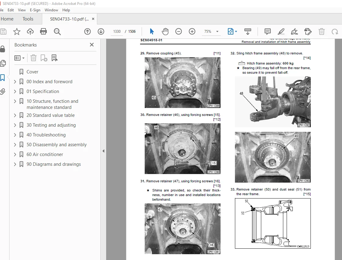
Disassembly and assembly of hitch frame assembly 1335
500 Hydraulic system 1343
Removal and installation of flow amp valve 1344
Removal and installation of hoist valve assembly 1347
Disassembly and assembly of hydraulic cylinder assembly 1351
SEN04919-01 1343
HM250-2 1343
Machine model Serial number 1343
Removal and installation of flow amp valve 2 1343
Removal and installation of hoist valve assembly 5 1343
Disassembly and assembly of hydraulic cylinder assembly 9 1343
600 Body 1359
Removal and installation of body assembly 1360
SEN04920-01 1359
HM250-2 1359
Machine model Serial number 1359
Removal and installation of body assembly 2 1359
700 Cab and its attachments 1363
Method of tilting cab up 1364
Removal and installation of operator’s cab glass (Stuck glass) 1373
Disassembly and assembly of operator’s seat assembly 1380
Removal and installation of air conditioner unit assembly 1390
Removal and installation of cab assembly 1366
800 Electrical system 1399
Removal and installation of engine controller 1400
Removal and installation of retarder controller 1401
Removal and installation of transmission 1402
Removal and installation of KOMTRAX terminal assembly 1403
60 Air conditioner 1405
100 Structure, function, testing, adjusting, and troubleshooting 1405
Precautions before work 1407
Structure and function 1408
Air conditioner component 1408
Configuration and function of refrigerating cycle 1409
Outline of refrigerating cycle 1410
Air conditioner unit 1412
Function of major components in the air conditioner unit 1413
Blower and intake unit 1415
Compressor 1417
Receiver drier 1419
Air conditioner control panel 1421
Testing, adjusting and troubleshooting 1423
Caution about refrigerant 1423
Troubleshooting procedure 1424
Block diagram and circuit diagram of control system 1425
Detail of air conditioner unit 1427
Arrangement of connector pins 1429
Part and connector locations 1430
Cab tilting 1434
Testing air leakage (ducts) 1435
Testing with self-diagnosisfunction (indication on controlpanel) 1438
Testing temperature control 1439
Testing vent (mode) changeover 1441
Testing Recirc/Fresh changeover 1442
Testing evaporator temperaturesensor 1444
Testing relays 1447
Troubleshooting chart 1 1448
Troubleshooting chart 2 1449
Troubleshooting for electrical system (E mode) 1452
E-1 Power supply system (Air conditioner does not operate) 1453
E-2 Compressor system (Air is not cooled) 1457
E-3 Blower motor system (No air comes out or air flow is abnormal) 1460
E-4 Temperature cannot be controlled 1463
E-5 Vent (mode) cannot be changed over 1465
E-6 Recirc/Fresh air cannot be changed over 1467
Troubleshooting with gauge pressure 1469
Connection of service tool 1471
Precautions for connecting airconditioner piping 1472
Handling of compressor oil 1473
1 Control of compressor oil 1473
2 Adding of compressor oil 1473
3 Compressor replacement 1474
4 Applying compressor oil for O-ring 1474
90 Diagrams and drawings 1477
100 Hydraulic diagrams and drawings 1477
Power train hydraulic circuit diagram 1479
Steering and hoist hydraulic circuit diagram 1481
Brake hydraulic circuit diagram 1483
Brake cooling hydraulic circuit diagram 1485
Steering and hoist hydraulic circuit diagram 1481
200 Electrical diagrams and drawings 1487
Electrical circuit diagram for inside cab (1/4) 1489
Electrical circuit diagram for inside cab (2/4) 1491
Electrical circuit diagram for inside cab (3/4) 1493
Electrical circuit diagram for inside cab (4/4) 1495
Electrical circuit diagram for outside cab (1/3) 1497
Electrical circuit diagram for outside cab (2/3) 1499
Electrical circuit diagram for outside cab (3/3) 1501
Connectors table and arrangement drawing 1503
DESCRIPTION:
Komatsu HM250-2 Dump Truck Shop Manual SEN04733-10 – PDF DOWNLOAD
SERIAL NUMBERS 2001 and up
How to read the shop manual
1. Composition of shop manual
This shop manual contains the necessary technical information for services performed in a workshop.
For ease of understanding, the manual is divided into the following sections.
00. Index and foreword
This section explains the shop manuals list, table of contents, safety, and basic information.
01. Specification
This section explains the specifications of the machine.
10. Structure, function and maintenance standard
This section explains the structure, function, and maintenance standard values of each component.
The structure and function sub-section explains the structure and function of each component. It
serves not only to give an understanding of the structure, but also serves as reference material for
troubleshooting. The maintenance standard sub-section explains the criteria and remedies for disassembly
and service.
20. Standard value table
This section explains the standard values for new machine and judgement criteria for testing,
adjusting, and troubleshooting. This standard value table is used to check the standard values in
testing and adjusting and to judge parts in troubleshooting.
30. Testing and adjusting
This section explains measuring instruments and measuring methods for testing and adjusting, and
method of adjusting each part. The standard values and judgement criteria for testing and adjusting
are explained in Testing and adjusting.
40. Troubleshooting
This section explains how to find out failed parts and how to repair them. The troubleshooting is
divided by failure modes. The “S mode” of the troubleshooting related to the engine may be also
explained in the Chassis volume and Engine volume. In this case, see the Chassis volume.
50. Disassembly and assembly
This section explains the special tools and procedures for removing, installing, disassembling, and
assembling each component, as well as precautions for them. In addition, tightening torque and
quantity and weight of coating material, oil, grease, and coolant necessary for the work are also
explained.
90. Diagrams and drawings (chassis volume)/Repair and replacement of parts (engine volume)
q Chassis volume
This section gives hydraulic circuit diagrams and electrical circuit diagrams.
q Engine volume
This section explains the method of reproducing, repairing, and replacing parts.
S.V 29/12/24


