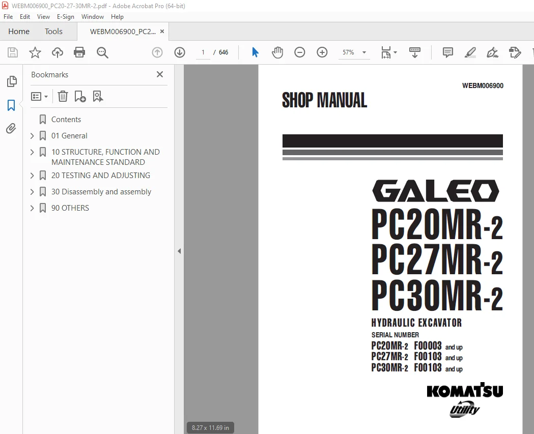
Komatsu GALEO PC20MR-2 PC27MR-2 PC30MR-2 Hydraulic Excavator Shop Manual PDF
$31.95
Komatsu GALEO PC20MR-2 PC27MR-2 PC30MR-2 Hydraulic Excavator Shop Manual WEBM006900 – PDF DOWNLOAD
SERIAL NUMBER
PC20MR-2 F00003 and up
PC27MR-2 F00103 and up
PC30MR-2 F00103 and up
Description
Komatsu GALEO PC20MR-2 PC27MR-2 PC30MR-2 Hydraulic Excavator Shop Manual WEBM006900 – PDF DOWNLOAD
FILE DETAILS:
Komatsu GALEO PC20MR-2 PC27MR-2 PC30MR-2 Hydraulic Excavator Shop Manual WEBM006900 – PDF DOWNLOAD
Language : English
Pages : 646
Downloadable : Yes
File Type : PDF
IMAGES PREVIEW OF THE MANUAL:
TABLE OF CONTENTS:
Komatsu GALEO PC20MR-2 PC27MR-2 PC30MR-2 Hydraulic Excavator Shop Manual WEBM006900 – PDF DOWNLOAD
SERIAL NUMBER
PC20MR-2 F00003 and up
PC27MR-2 F00103 and up
PC30MR-2 F00103 and up
Contents 4
01 General 9
Specification dimension drawing 10
Working range drawing 11
Specifications 12
Weight table 21
Lubricants, fuel and coolant specifications 25
10 STRUCTURE, FUNCTION AND MAINTENANCE STANDARD 27
PTO 28
Cooling system 30
Power train 34
Swing circle 35
Track frame 37
Swing machinery 39
Idler cushion 41
Idler 42
Hydraulic components layout drawing 53
Hydraulic tank 54
Track roller 44
Carrier roller 45
Sprocket 46
Track shoe 51
Center swivel joint 56
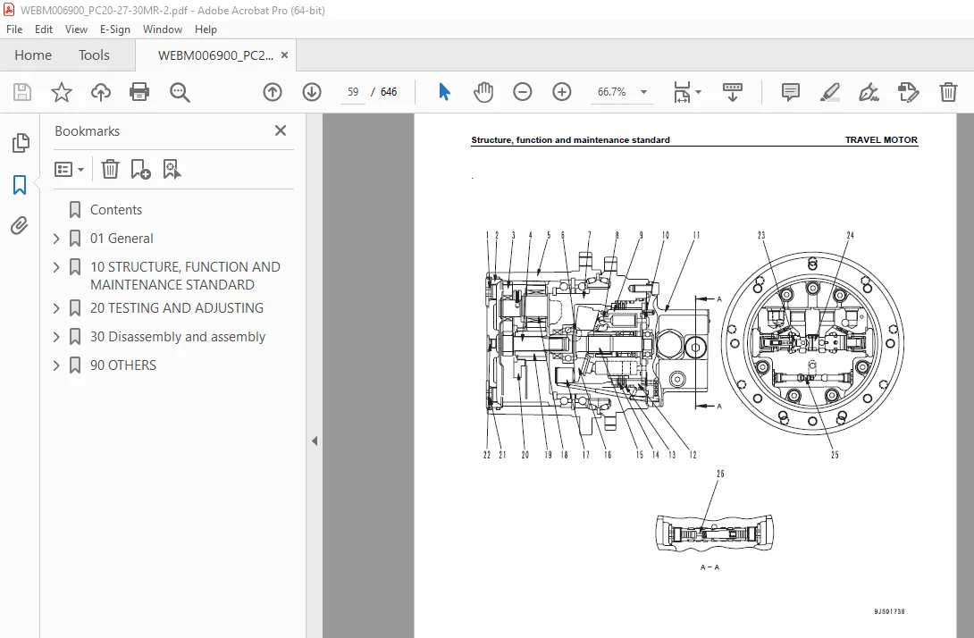
Travel motor 58
Travel motor 67
Hydraulic cylinder 75
Solenoid valve 80
Hydraulic pump 81
CONTROL VALVE 94
Control valve 106
Clss 130
Operation for each function and valve 133
Swing motor 155
Swing motor 165
Ppc valve 172
Work equipment 180
Dimensions of each part of work equipment 183
Floor 187
Engine control 188
Electric control system 190
Component parts of system 195
Monitor system 196
Monitor panel 197
Sensors 199
20 TESTING AND ADJUSTING 201
Standard value table for engine related parts 202
Standard value table for chassis related parts 205
Testing and adjusting 227
List of testing, adjusting, and troubleshooting tools 228
Measuring engine speed 230
Measurement of exhaust gas color 232
Adjusting valve clearance 233
Adjusting valve clearance 234
Measuring compression pressure 237
Measuring compression pressure 238
Measuring engine oil pressure 239
Testing and adjusting fuel injection timing 241
Testing and adjusting fuel injection timing 243
Bleeding air from fuel circuit 246
Testing and adjusting alternator belt tension 247
Testing and adjusting alternator belt tension 248
Adjusting fuel control lever linkage 249
Measurement of clearance in swing circle bearings 250
Testing wear of sprocket 251
Testing and adjusting track shoe tension 252
Testing and adjusting oil pressures in work equipment, travel, swing, and blade circuits 253
Measuring and adjusting oil pressures in work equipment, travel, boom swing, swing, and blade circuits 256
Measuring control circuit basic pressure 260
Testing and adjusting pump ls differential pressure 261
Measuring and adjusting ls differential pressure 263
Measuring solenoid valve output pressure 265
Measuring ppc valve output pressure 266
Adjusting play of work equipment and swing ppc valves 270
Measuring swing holding brake release pressure 271
Measuring swing holding brake release pressure 273
Testing and adjusting travel deviation 274
Measurement of oil leakage from cylinder 275
Releasing residual pressure from hydraulic circuit 277
Bleeding air from cylinder 278
Pressurizing hydraulic tank 279
Bleeding air from each part 280
How to open and close (tilt) floor 282
Inspection procedures for diode 284
Troubleshooting 285
Points to remember when troubleshooting 286
Sequence of events in troubleshooting 287
Points to remember when carrying out maintenance 288
Checks before troubleshooting 296
Classification and procedures of troubleshooting 297
Connectors list and stereogram 300
Classification and procedures of troubleshooting 308
Types and locations of connectors 311
Connector arrangement diagram 314
Connection table for connector pin numbers 318
T-adapter – boxes and t-adapter table 341
Troubleshooting of electrical system PC20MR-2 (Except monitor panel) (E mode) 345
Before starting e-mode troubleshooting 346
Information contained in troubleshooting table 348
E-1 Engine does not start 349
E-2 Engine does not stop 355
E-3 When safety lock lever is in FREE position, whole work equipment, travel, swing, and blade systems do not work 357
E-4 When safety lock lever is in LOCK position, whole work equipment, travel, swing, and blade systems work 360
E-5 Windshield wiper does not operate [Cab specification] 362
E-6 Windshield washer does not operate [Cab specification] 364
E-7 Heater does not operate 366
Troubleshooting of electrical system PC27MR-2 PC30MR-2 (Except monitor panel) (E mode) 371
Before starting e-mode troubleshooting 372
Information contained in troubleshooting table 373
E-1 Engine does not start 374
E-2 Engine does not stop 378
E-3 When work equipment lock (PPC basic pressure lock) lever is set in LOCK position, work equipment still moves 380
E-4 Windshield wiper does not operate 382
E-5 Windshield washer does not operate 384
E-6 Travel alarm does not sound 386
E-7 Heater does not operate 388
Troubleshooting of hydraulic and mechanical system (PC20MR-2) (H mode) 393
INFORMATION CONTAINED IN TROUBLESHOOTING TABLE 394
H-1 Speed or power of whole work equipment, travel, swing, and blade is low 395
H-2 Engine speed lowers extremely or engine stalls 398
H-3 Whole work equipment, travel system, swing system, and blade do not work 399
H-4 Abnormal sound comes out from around hydraulic pump 402
H-5 Fine control performance or response is low 402
H-6 Speed or power of boom is low 403
H-7 Speed or power of arm is low 404
H-8 Speed or power of bucket is low 405
H-9 Speed or power of boom swing is low 406
H-10 Work equipment does not move singly 406
H-11 Work equipment hydraulic drift is large 407
H-12 Time lag of work equipment is large 408
H-13 In compound operation of work equipment, speed of part loaded more is low 408
H-14 Machine deviates during travel 409
H-15 Travel speed or travel power is low 411
H-16 Machine is not steered well or steering power is low 411
H-17 Travel speed does not change 412
H-18 Travel motor does not work (one side only) 412
H-19 Speed or power of swing is low 413
H-20 Machine does not swing 415
H-21 Swing acceleration performance is low 417
H-22 Machine overruns when it stops swinging 418
H-23 Large shock is made when machine stops swinging 419
H-24 When upper structure stops swinging, it makes large sound 419
H-25 Hydraulic drift of swing is large 420
H-26 Speed or power of blade is low 421
H-27 Blade does not move 422
H-28 Hydraulic drift of blade is large 422
Troubleshooting of hydraulic and mechanical system (PC27MR-2 PC30MR-2) (H mode) 423
Information contained in troubleshooting table 424
H-1 Speed or power of whole work equipment, travel, swing, and blade is low 425
H-2 Engine speed lowers extremely or engine stalls 429
H-3 Whole work equipment, travel system, swing system, and blade do not work 430
H-4 Abnormal sound comes out from around hydraulic pump 434
H-5 Fine control performance or response is low 434
H-6 Speed or power of boom is low 435
H-7 Speed or power of arm is low 436
H-8 Speed or power of bucket is low 437
H-9 Speed or power of boom swing is low 438
H-10 Work equipment does not move singly 438
H-11 Work equipment hydraulic drift is lARge 439
H-12 Time lag of work equipment is large 440
H-13 In compound operation of work equipment, speed of part loaded more is low 440
H-14 Machine deviates during travel 441
H-15 Travel speed or travel power is low (while work equipment is normal) 442
H-16 Machine is not steered well or steering power is low 443
H-17 Travel speed does not change 443
H-18 Travel motor on only one side does not work 444
H-19 Speed or power of swing is low 445
H-20 Machine does not swing 447
H-21 Swing acceleration performance is low 449
H-22 Machine overruns when it stops swinging 450
H-23 Large shock is made when machine stops swinging 451
H-24 When upper structure stops swinging, it makes large sound 451
H-25 Hydraulic drift of swing is large 452
H-26 Speed or power of blade is low 453
H-27 Blade does not move 454
H-28 Hydraulic drift of blade is large 454
Troubleshooting of monitor panel system (PC20MR-2) (M mode) 455
Before starting M-mode troubleshooting 456
Information contained in troubleshooting table 458
M-1 When starting switch is turned ON, no monitor/gauge operates 460
M-2 When starting switch is turned ON, some monitors/gauges do not operate 462
M-3 Caution buzzer does not sound or does not stop sounding 463
M-4 While engine is running, engine oil pressure monitor flashes 465
M-5 While engine is running, charge level monitor flashes 466
M-6 Preheating system does not operate 468
M-7 Coolant temperature gauge does not indicate normally 471
M-8 Fuel level gauge does not indicate normally 474
M-9 Service meter does not operate while engine is running 476
M-10 Travel speed shifting system does not operate normally 477
M-11 Monitor panel night lamp and working lamp do not right up 480
Troubleshooting of monitor panel (PC27-30MR-2) system (M-mode) 485
Before starting M-mode troubleshooting 486
Information contained in troubleshooting table 487
M-1 When starting switch is turned ON, any item does not operate 489
M-2 When starting switch is turned ON, some items do not operate 490
M-3 Alarm buzzer is abnormal 491
M-4 Engine oil pressure caution is turned ON 493
M-5 Charge level caution is turned ON 494
M-6 Preheating system does not operate or preheater does not become hot 496
M-7 Coolant temperature gauge is abnormal 497
M-8 Fuel level gauge is abnormal 500
M-9 Service meter does not operate while engine is running 503
M-10 2nd travel speed is not selected 505
M-11 Working lamp does not light up 507
TROUBLESHOOTING OF ENGINE (PC20MR-2) (S-MODE) 511
Troubleshooting of engine (s-mode) 512
TROUBLESHOOTING OF ENGINE (PC27-30MR-2) (S-MODE) 519
Method of using troubleshooting charts 520
S-1 Starting performance is poor (Starting always takes time) 524
S-2 Engine does not start 526
S-3 Engine does not pick up smoothly (Follow-up is poor) 529
S-4 Engine stops during operations 530
S-5 Engine does not rotate smoothly (Hunting) 531
S-6 Engine lacks output or lacks power 532
S-7 Exhaust smoke is black (Incomplete combustion) 533
S-8 Oil consumption is excessive or exhaust smoke is blue 534
S-9 Oil becomes contaminated quickly 535
S-10 Fuel consumption is excessive 536
S-11 Oil is in cooling water, or water spurts back, or water level goes down 537
S-12 Oil pressure caution lamp lights up (Drop in oil pressure) 538
S-13 Oil level rises (Water, fuel in oil) 539
S-14 Water temperature becomes too high (Overheating) 540
S-15 Abnormal noise is made 541
S-16 Vibration is excessive 542
30 Disassembly and assembly 543
How to read this manual 544
Precautions when performing operation 546
Special tool list 548
Removal and installation of fuel injection pump assembly 552
Removal and installation of fuel injection pump assembly 554
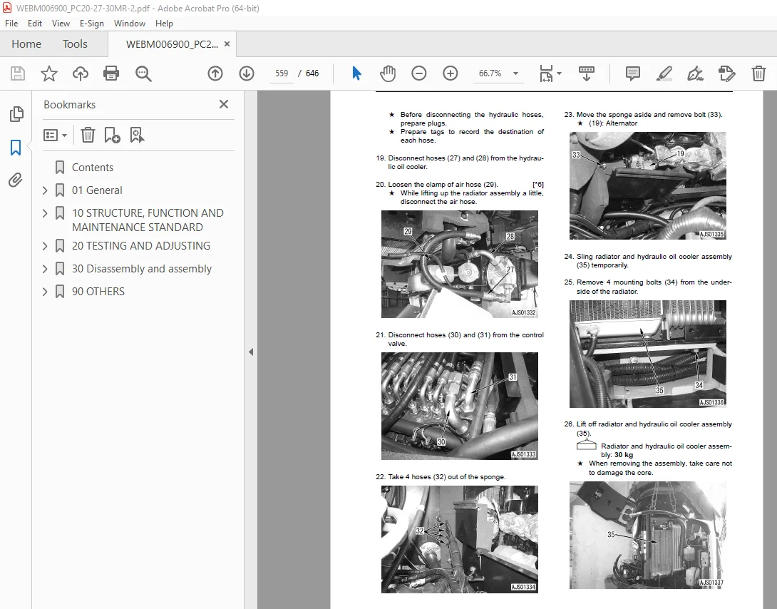
Removal and installation of radiator and hydraulic oil cooler assembly 556
Removal and installation of radiator and hydraulic oil cooler assembly 561
Removal and installation of engine and hydraulic pump assembly 565
Removal and installation of engine and hydraulic pump assembly 567
Removal and installation of track shoe assembly 570
Disassembly and assembly of idler assembly 571
Disassembly and assembly of recoil spring assembly 573
Disassembly and assembly of carrier roller assembly 576
Disassembly and assembly of track roller assembly 577
Removal and installation of center swivel joint assembly 578
Removal and installation of center swivel joint assembly 580
Disassembly and assembly of center swivel joint assembly 582
Removal and installation of floor frame assembly 584
Removal and installation of floor frame assembly 589
Removal and installation of swing motor and swing machinery assembly 593
Removal and installation of swing motor and swing machinery assembly 594
Disassembly and assembly of swing motor and swing machinery assembly 595
Removal and installation of work equipment assembly 601
Removal and installation of revolving frame assembly 603
Removal and installation of revolving frame assembly 605
Removal and installation of swing circle assembly 607
Disassembly and assembly of control valve assembly 608
Disassembly and assembly of hydraulic cylinder assembly 612
Disassembly and assembly of hydraulic cylinder assembly 616
Removal and installation of air conditioner unit assembly 620
Removal and installation of front window assembly 623
Removal and installation of operator’s cab glass (stuck glass) 624
90 OTHERS 633
Hydraulic circuit diagram (PC20MR-2) 635
Hydraulic circuit diagram (PC27MR-2) 637
Hydraulic circuit diagram (PC30MR-2) 639
Electrical circuit diagram (PC20MR-2) 641
Electrical circuit diagram (PC27-30MR-2) 643
S.V 30/12/24


