Komatsu Forklift Truck FH35-2 FH40-2 FH45-2 FH50-2 Service Manual SM164 PDF
$37.95
Komatsu Forklift Truck FH35-2 FH40-2 FH45-2 FH50-2 Service Manual SM164 – PDF DOWNLOAD
SERVICE MANUAL
FH-2 Series Forklift Truck
Serial No. 140001-
FH-2
FH35-2
FH40-2
FH45-2
FH50-2
Description
Komatsu Forklift Truck FH35-2 FH40-2 FH45-2 FH50-2 Service Manual SM164 – PDF DOWNLOAD
FILE DETAILS:
Komatsu Forklift Truck FH35-2 FH40-2 FH45-2 FH50-2 Service Manual SM164 – PDF DOWNLOAD
Language : English
Pages :1226
Downloadable : Yes
File Type : PDF
IMAGES PREVIEW OF THE MANUAL:
DESCRIPTION:
Komatsu Forklift Truck FH35-2 FH40-2 FH45-2 FH50-2 Service Manual SM164 – PDF DOWNLOAD
SERVICE MANUAL
FH-2 Series Forklift Truck
Serial No. 140001-
FH-2
FH35-2
FH40-2
FH45-2
FH50-2
General precautions
A machine handled incorrectly is dangerous. Before starting work, read and understand what is described in the Operation and Maintenance Manual.
- Read and understand the meaning of all the safety labels on the machine before performing any greasing or repairs (see safety label locations and explanation of precautions in Operation and Maintenance Manual).
- Tools and removed parts in the workshop should be well organized. Always keep tools and parts in their correct places. Always keep the work area clean and make sure that there is no dust, dirt, oil, or water on the floor. Smoke only in the designated areas. Never smoke while working.
- Keep all tools in good condition, learn the correct way to use them, and use the proper ones. Check the tools, machine, forklift truck, service car thoroughly before starting the work.
- Always wear safety shoes and helmet when performing any operation. Do not wear loose clothes, or clothes with buttons missing.
- Always wear protective eyeglasses when hammering parts, grinding parts with a grinder, any time when dust, metal or sparks can fly into the eyes.
- When performing any operation with multiple workers, always agree on the operating procedure before starting. Be clear in verbal communication, and observe hand signals.
- Hang an “UNDER REPAIR” warning tag in the operator’s compartment to use in case the lift truck stops working.
- Before starting work:
- Work and operation which require license or qualification should be performed by qualified workers.
- Welding repairs should be performed by trained and experienced welders. When performing welding work, always wear welding gloves, apron, welding goggles, cap and other clothes suited for welding work.
- Warm up before starting the work with exercise which increases alertness and the range of motion.
- Avoid prolonged work, and take a rest at times to keep in good condition. Rest at designated safe areas.
- Do not start the engine by pushing the lift truck. If the lift truck starts moving suddenly, an accident can occur.
- TABLE OF CONTENTS:
Komatsu Forklift Truck FH35-2 FH40-2 FH45-2 FH50-2 Service Manual SM164 – PDF DOWNLOAD
SERVICE MANUAL
FH-2 Series Forklift Truck
Serial No. 140001-
FH-2
FH35-2
FH40-2
FH45-2
FH50-2
CONTENTS 3
00 Foreword 19
Safety and basic information 21
Composition of the shop manual 21
Safety notice for operation 22
Safety points 22
General precautions 23
Precautions for preparatory work 23
Precautions during work 24
Precautions for slinging work and making signals 25
Precautions for slinging up 26
Precautions for slinging down 26
Precautions for using mobile crane 26
Precautions for using overhead traveling crane 26
Selecting wire ropes 27
Precautions for slinging lift truck onto the trailer 27
Precautions for jacking-up lift truck to check or replace a tire 28
Precautions for slinging lift truck when checking or replacing a tire 28
Precautions for inspection and inflation of the tire 28
Handling of tires 28
Precautions for disconnecting air conditioner piping 29
Precautions for installing air conditioner piping 29
Precautions to prevent fire 30
Fire caused by fuel, oil, coolant or window washer fluid 30
Fire caused by accumulation or attachment of flammable material 30
Fire coming from electric wiring 30
Fire caused by piping 30
Fire around the machine due to highly heated exhaust gas 30
Explosion caused by lighting equipment 30
Action if fire occurs 31
Precautions for handling hydraulic equipment 32
Select an appropriate workplace 32
Disassembly and maintenance work in the field 32
Sealing openings to prevent oil leaks 32
Preventing intrusion of foreign materials during refilling 32
Replacing high temperature hydraulic oil 32
Flushing operation 33
Cleaning operation 33
Precautions for disconnecting and connecting piping 34
Precautions for removal and disassembling work 34
Parts list for the disassembly of face seal type hoses and tubes 34
Parts list for the disconnection of the taper seal type hoses and tubes 35
Parts list for the disconnection of the split flange type hoses and tubes 36
Parts list for the removal of O-ring boss type joint 37
Parts list for the removal of taper pipe thread type joint 38
Precautions for installation and assembling work 39
Precautions when work is completed 40
Precautions for handling electrical equipment 41
Handling wiring harnesses and connectors 41
Main causes of failure in wiring harness 41
Precautions for handling fuel system equipment 43
Select an appropriate workplace 43
Seal the openings 43
Clean dirty parts 43
Precautions for replacing fuel filter cartridge 43
Precautions for handling intake system equipment 44
Select an appropriate workplace 44
Seal the openings 44
Practical use of KOMTRAX 45
Merit of using KOMTRAX 45
How to use KOMTRAX practically 45
How to operate KOMTRAX 45
Disconnect and connect push-pull type coupler 46
Type 1 push-pull type coupler 46
Type 2 push-pull type coupler 48
Type 3 push-pull type coupler 49
Precautions for disconnection and connection of connectors 50
Disconnecting connectors 50
Connecting connectors 51
Drying wiring harness 52
Handling controller 53
Precautions for troubleshooting electrical circuits 53
Connector coupling and decoupling 54
Deutsch connector 54
Connector with slide lock 55
Connector with pull lock 57
Connector with push lock 58
Connector with rotating housing 60
How to read electrical wire code 61
Type, symbol, and material (Table 1) 62
Dimensions (Table 2) 63
Color codes (Table 3) 65
Types of circuits and color codes 66
Explanation of terms for maintenance standard 67
Standard dimension and tolerance 67
Standard clearance and standard value 67
Standard interference 67
Repair limit and allowable value or allowable dimension 68
Allowable clearance 68
Allowable interference 68
Abbreviation list 69
List of abbreviations used in the text 69
List of abbreviations used in the circuit diagrams 75
Standard tightening torque tables 76
Tightening torque for bolts and nuts 76
Tightening torque for O-ring boss piping joints 80
Tightening torque for O-ring boss plugs 81
Tightening torque for hose (taper seal type and face seal type) 82
Tightening torque for face seal joints 83
Tightening torque for 102, 107, and 114 series engines 83
Tightening torque for 102, 107, and 114 series engines (joint bolts) 84
Tightening torque for tapered screws on 102,107, and 114 series engines 84
Conversion tables 85
01 General Information 95
Specification Drawing 97
Weight Table 99
Lubricants 100
Lubrication chart 100
Lubricant list 101
10 Structure and function 103
Engine and cooling system 105
Variable flow turbocharger 105
Piping drawing of EGR system 109
Circuit diagram of EGR system 111
EGR valve 112
EGR cooler 114
Layout drawing of KCCV 116
KCCV ventilator 118
CDR valve 119
KDOC muffler 122
Cooling system 124
Power train 126
Power train system diagram 127
PTO 128
HST piping diagram 130
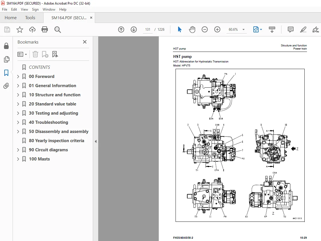
HST pump 131
HST charge pump 141
Charge safety valve 142
HST motor 143
Axle 153
Differential 154
Steering system 157
Control valve to power steering cylinder piping diagram 157
Orbitrol valve 158
Brake system 160
Undercarriage and frame 174
Rear axle 174
Frame 175
Hydraulic system 176
Control valve piping diagram (tank to control valve) 176
Hydraulic tank piping diagram 177
Control valve to tilt and lift cylinders piping diagram 178
Attachment piping diagram 179
Work equipment control lever linkage 180
Work equipment and steering pump 181
Control valve 188
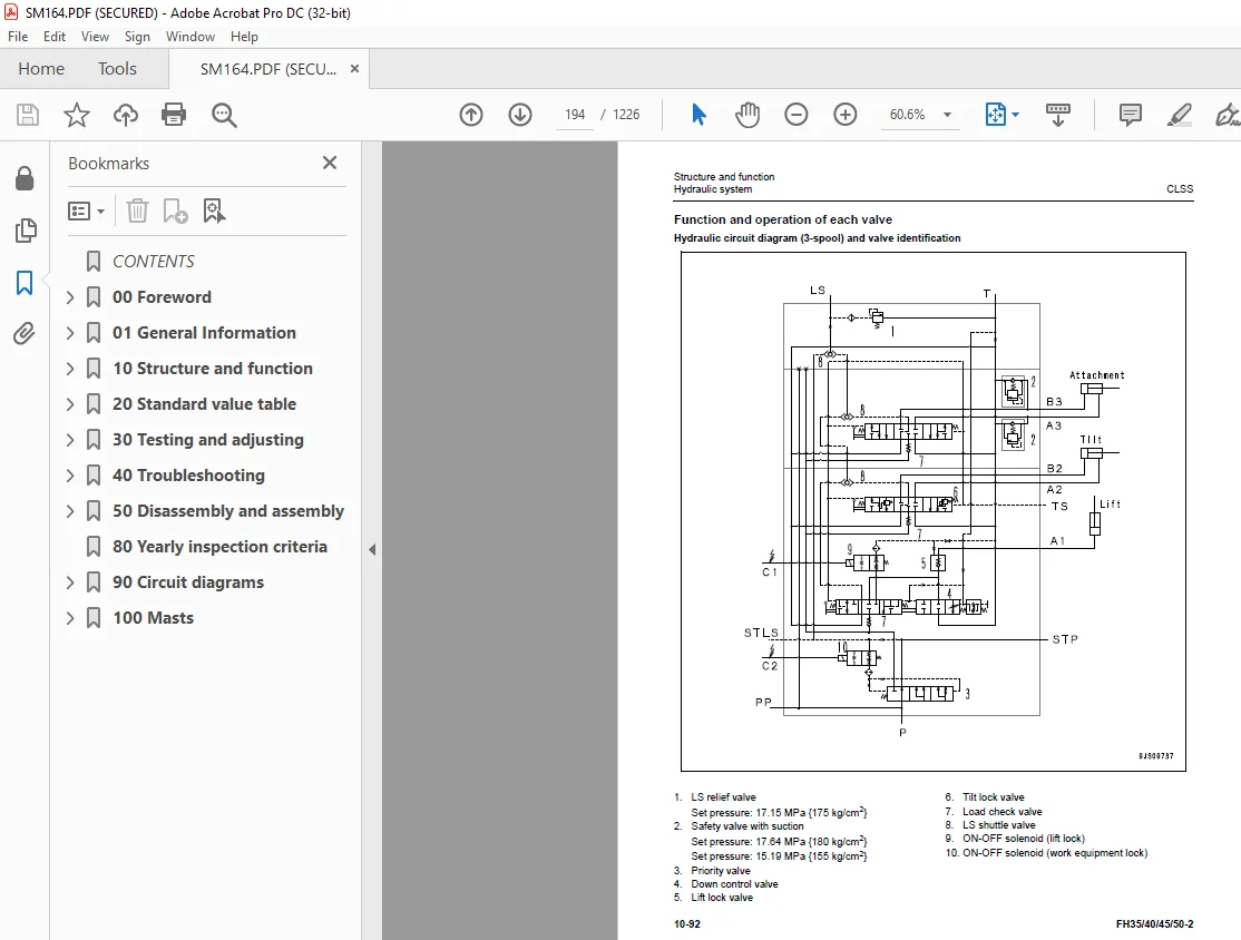
CLSS 192
Work equipment 208
Mast 208
Carriage 214
Fork 215
Electrical system 216
Electrical control system 216
HST controller 241
System component parts 244
Accelerator pedal sensor 251
EPACS controller 252
Monitor system 256
KOMTRAX system 258
Sensors 261
Combination switch 271
Seat switch, seat belt switch 272
Flasher 273
Relay box 274
20 Standard value table 277
Standard value table for engine: FH35-2 279
Performance 279
Air intake and exhaust system 279
Electric system 279
Main body 280
Fuel system 280
Lubrication system 281
Cooling system 281
Standard value table for engine: FH40-2 282
Performance 282
Air intake and exhaust system 282
Electric system 282
Main body 283
Fuel system 283
Lubrication system 284
Cooling system 284
Standard value table for engine: FH45-2 285
Performance 285
Air intake and exhaust system 285
Electric system 285
Main body 286
Fuel system 286
Lubrication system 287
Cooling system 287
Standard value table for engine: FH50-2 288
Performance 288
Air intake and exhaust system 288
Electric system 288
Main body 289
Fuel system 289
Lubrication system 290
Cooling system 290
Standard value table for machine: FH35-2 291
Engine speed 291
Pedal and linkage 291
Parking brake lever 291
Power train 292
Tire 292
Accumulator 292
Brake 293
Parking brake 293
Steering wheel 294
Work equipment 294
Standard value table for machine: FH40-2 295
Engine speed 295
Pedal and linkage 295
Parking brake lever 295
Power train 296
Tire 296
Accumulator 296
Brake 297
Parking brake 297
Steering wheel 298
Work equipment 298
Standard value table for machine: FH45-2 299
Engine speed 299
Pedal and linkage 299
Parking brake lever 299
Power train 300
Tire 300
Accumulator 300
Brake 301
Parking brake 301
Steering wheel 302
Work equipment 302
Standard value table for machine: FH50-2 303
Engine speed 303
Pedal and linkage 303
Parking brake lever 303
Power train 304
Tire 304
Accumulator 304
Brake 305
Parking brake 305
Steering wheel 306
Work equipment 306
30 Testing and adjusting 307
Related information on testing and adjusting 309
Tools for testing and adjusting 309
Engine and cooling system 313
Testing engine speed 313
Testing exhaust gas color 315
Testing and adjusting valve clearance 317
Testing compression pressure 319
Testing blowby pressure 322
Testing engine oil pressure 323
Testing fuel pressure 324
Testing fuel return and leakage volume 325
Bleeding air from fuel system 327
Testing leakage from fuel system 329
Replacing engine oil and engine oil filter 331
Replacing KCCV filter element 332
Replacing fuel filter 334
Draining water from fuel pre-filter 337
Bleeding air from fuel filter 338
Radiator cleaning 339
Testing air cleaner and replacing filter element 340
Handling cylinder cutout mode operation 343
Handling no-injection cranking operation 344
Writing compensation values at replacement of fuel injector and engine controller 345
Testing alternator belt 349
Power train 351
Testing HST oil pressure 351
Checking oil level and changing oil in differential case 353
Changing PTO oil and cleaning strainer 354
Steering system 355
Initial setting of orbitrol valve 355
Brake system 356
Bleeding air from brake circuit 356
Testing brake oil pressure 357
Checking accumulator charge pressure 358
Testing braking performance 359
Testing wear of service brake disc 360
Checking parking brake 361
Testing and adjusting brake pedal 362
Testing and adjusting brake pedal angle sensor linkage 363
Hydraulic system 364
Releasing remaining pressure in hydraulic piping 364
Inspection of hydraulic tank 365
Work equipment 367
Bleeding air from lift cylinder 367
Adjusting mast 369
Adjusting fork carriage 372
Adjustment of chain 374
Electrical system 375
Handling engine controller voltage circuit 375
Testing procedure for diode 376
Special functions of monitor panel 377
KOMTRAX terminal start-up procedure 422
When KOMTRAX terminal is replaced 422
Radio station establishment on lift truck side 422
Troubleshooting radio station establishment 425
40 Troubleshooting 427
Preparing for troubleshooting 429
Points to remember when troubleshooting 429
Troubleshooting process chart 430
Checks before troubleshooting 432
Getting a troubleshooting number 434
Table of failure symptoms and codes 435
Troubleshooting summary table 438
Locations of fuses 440
Connector list and layout 444
Connector pinout tables 452
T-box and T-adapter list 492
Troubleshooting by failure code 496
Failure codes table 496
[2G40ZG] Low) Accumulator Oil Pressure 502
[6091NX] HST Oil Filter: Clogging 503
[7REAKA] DISC OR SHORT_G) ACC input 1 504
[7REHKA] ACC input 2 506
[AB00KY] SHORT) Alternator 508
[AB00MA] Low) Battery Charge Voltage 510
[B@BAZG] Eng Oil press Low 512
[B@BCNS] Eng Water Overheat 513
[B@CRNS] Overheating HST Oil 514
[CA115] Eng Ne & Bkup Speed Sens Err 515
[CA122] Chg Air Press Sens High Err 516
[CA131] Throttle Sensor High Error 518
[CA132] Throttle Sensor Low Error 520
[CA144] Coolant Temp Sens High Error 523
[CA145] Coolant Temp Sens Low Error 525
[CA153] Chg Air Temp Sens High Error 527
[CA154] Chg Air Temp Sens Low Error 529
[CA187] Sens 2 Supply Volt Low Err 531
[CA221] Ambient Press Sens High Err 533
[CA222] Ambient Press Sens Low Error 535
[CA227] Sens 2 Supply Volt High Err 537
[CA234] Eng Overspeed 538
[CA238] Ne Speed Sens Sup V Low Err 539
[CA239] Ne Speed Sens Sup V High Err 541
[CA271] IMV/PCV1 Short Error 543
[CA272] IMV/PCV 1 Open Error 545
[CA322] Inj #1 (L#1) Open/Short Error 547
[CA324] Inj #3 (L#3) Open/Short Error 549
[CA331] Inj #2 (L#2) Open/Short Error 551
[CA332] Inj #4 (L#4) Open/Short Error 553
[CA343] ECM Critical Internal Failure 555
[CA351] Injector Drive Circuit Error 556
[CA352] Sens 1 Supply Volt Low Err 557
[CA356] MAF Sensor High Error 559
[CA357] MAF Sensor Low Error 561
[CA386] Sens 1 Supply Volt High Err 564
[CA428] Water in Fuel Sensor High Error 565
[CA429] Water in Fuel Sensor Low Error 567
[CA431] Idle Validation Sw Error 569
[CA432] Idle Validation Process Err 572
[CA435] Eng Oil Press SW Error 575
[CA441] Battery Voltage Low Error 577
[CA442] Battery Voltage High Error 579
[CA449] Rail Press Very High Error 580
[CA451] Rail Press Sensor High Error 581
[CA452] Rail Press Sensor Low Error 583
[CA466] KVGT Motor D Position Error 585
[CA515] Rail Press Sens Sup V Hi Err 587
[CA516] Rail Press Sens Sup V Lo Err 589
[CA553] Rail Press High Error 591
[CA555] Crankcase Press High Error 1 592
[CA556] Crankcase Press High Error 2 593
[CA559] Rail Press Low Error 594
[CA689] Eng Ne Speed Sensor Error 597
[CA691] Intake Air Temp Sens Hi Err 600
[CA692] Intake Air Temp Sens Low Err 602
[CA697] ECM Int Temp Sens High Error 604
[CA698] ECM Int Temp Sens Low Error 605
[CA731] Bkup Speed Sens Phase Error 606
[CA778] Eng Bkup Speed Sensor Error 607
[CA1117] Persistent Data Lost Error 610
[CA1695] Sens 5 Supply Volt High Err 611
[CA1696] Sens 5 Supply Volt Low Error 612
[CA1843] Crankcase Press Sens Hi Err 613
[CA1844] Crankcase Press Sens Low Err 615
[CA1896] EGR Valve Stuck Error 617
[CA1942] Crankcase Press Sens Err 618
[CA1961] EGR_Motor D IC Temp Err (H) 619
[CA2185] Throt Sens Sup Volt High Err 620
[CA2186] Throt Sens Sup Volt Low Err 621
[CA2249] Rail Press Very Low Error 623
[CA2272] EGR Valve Pos Sens Low Error 624
[CA2311] IMV Solenoid Error 626
[CA2349] EGR Valve Solenoid Open Err 627
[CA2353] EGR Valve Solenoid Short Err 629
[CA2357] EGR Valve Servo Error 631
[CA2555] Grid Htr Relay Error (Open) 632
[CA2556] Grid Htr Relay Error (Short) 634
[CA2765] Inj Trim Data error 636
[CA3419] MAF Sens Sup Volt High Error 637
[CA3421] MAF Sens Sup Volt Low Error 639
[CA3724] Motor Driver Power Low Error 641
[CA3918] KVGT Stuck Error 643
[CA3919] Driver IC Over Temp Err, KVGT 644
[CA3921] KVGT Servo Error 2 645
[CA3922] KVGT Motor Driver Open Err 646
[CA3923] KVGT Motor Driver Short Err 648
[D110KA] DISC OR SHORT) H/Con Relay 650
[D110KB] SHORT_G) Hst Con Relay 652
[D140KB] SHORT_G) Starter Relay 654
[D140KY] SHORT) Starter Relay 656
[D160KA] DISC) Back Lamp Relay 658
[D160KB] SHORT_G) Back Lamp Relay 660
[D160KY] SHORT) Back Lamp Relay 662
[D161KB] SHORT_G) Back Alarm Relay 664
[D161KY] SHORT) Back Alarm Relay 665
[D190KB] SHORT_G) ACC Power Relay 666
[D190KY] SHORT) ACC Power Relay 668
[D19SKB] SHORT_G) Forward Alarm Relay 669
[D19SKY] SHORT) Forward Alarm Relay 670
[D19TKB] SHORT_G)OverspeedAlarmRelay 671
[D19TKY] SHORT) Overspeed Alarm Relay 672
[D19UKA] DISC) Pump EPC Cut Relay 673
[D19UKB] SHORT_G) Pump EPC Cut Relay 675
[D19UKY] SHORT) Pump EPC Cut Relay 677
[D5ZTKA] DISC OR SHORT) EPC Earth RET 679
[D5ZKKA] DISC OR SHORT) Start Cut SIG 681
[D5ZKKB] SHORT_G) Start Cut SIG 682
[D811MC] ABNL) KOMTRAX 683
[D862KA] DISC) GPS Antenna 684
[D8ALKA] DISC) SYS-OPE Lamp (KMTX) 685
[D8ALKB] SHORT) SYS-OPE Lamp (KMTX) 686
[D8AQKR] ABNL) CAN COMM (KMTX) 687
[D8AQK4] ABNL) CAN COMM 2 (KMTX) 688
[DAF0KT] ABNL) EEPROM (MON) 690
[DAF0MB] ABNL) Monitor ROM 691
[DAF0MC] ABNL) Monitor 692
[DAF3KK] LOW) Power Moni 693
[DAFGMC] ABNL) GPS Module 695
[DAFLKA] DISC) Operating Lamp Line 696
[DAFLKB] SHORT) Operating Lamp Line 697
[DAFQKR] ABNL) CAN COMM (MON) 698
[DAJ000] ABNL) HST Con Memory 699
[DAJ0KK] LOW) HST/C Power Supply Volt 700
[DAJ0KT] ABNL) HST Con Memory 702
[DAJ0MC] RESET) Controller (HST) 703
[DAJ2KK] ABNL) HST/C Output Power 704
[DAJ5KX] SHORT_G OR SHORT) H/C Power 1 706
[DAJ9KQ] ABNL) Model Selection Line 708
[DAJJKB] SHORT_G) H/C Operating States 709
[DAJLKA] DISC) Operating Lamp Line 710
[DAJLKY] SHORT) Operating Lamp Line 711
[DAJRMA] ABNL) Model Selection Line 712
[DAJQKR] ABNL) CAN COMM (HST/C) 713
[DB2QKR] ABNL) CAN COMM (ENG/C) 716
[DB2RKR] ABNL) CAN COMMR (H/C~ENG/C) 719
[DDDTKA] DISC) Seat SW1 722
[DDDTKB] SHORT_G) Seat SW1 724
[DDDUKA] DISC) Seat SW2 726
[DDDUKB] SHORT_G) Seat SW2 728
[DDDVKA] ABNL) Seat SW 730
[DDDVKM] OPE-ERROR) Seat SW 732
[DDK6KA] DISC) Direction Lever 735
[DDK6KY] SHORT) Direction Lever 738
[DGS1KA] DISC) HST Temperature 740
[DGS1KB] SHORT_G) HST Temperature 742
[DH2FKA] DISC OR SHORT_G) Brake P SNSR 744
[DH2FKY] SHORT) Brake Press Sensor 746
[DHHBKA] DISC OR SHORT_G) HST PA SNSR 748
[DHHBKY] SHORT) HST PA Press Sensor 750
[DHHCKA] DISC OR SHORT_G) HST PB SNSR 752
[DHHCKY] SHORT) HST PB Press Sensor 754
[DHPCKA] DISC OR SHORT_G) Lift P SNSR 756
[DHPCKY] SHORT) Lift Press Sensor 758
[DJF1KA] DISC OR SHORT) Fuel Sensor 760
[DJF1L8] MISMATCH) Fuel Sensor 761
[DK70KA] DISC OR SHORT_G) Brake Pedal 763
[DK70KY] SHORT) Brake Pedal 765
[DLT4KA] DISC OR SHORT) Vehicle Speed A 767
[DLT4KA+DLT6KA] DISC 769
[DLT4LC] ABNL) Vehicle Speed Signal 772
[DLT4MA] ABNL) Vehicle Speed Sensor 773
[DLT4KA] DISC OR SHORT) Vehicle Speed B 774
[DV00KB] SHORT_G) Alarm Buzzer 776
[DV00KY] SHORT) Alarm Buzzer 778
[DV01KB] SHORT_G) Back Buzzer 779
[DV01KY] SHORT) Back Buzzer 780
[DW9MKA] DISC) LIFT LOCK SOL 781
[DW9MKB] SHORT_G) LIFT LOCK SOL 783
[DW9MKY] SHORT) LIFT LOCK SOL 785
[DW9NKA] DISC) WORK EQUIP LOCK SOL 786
[DW9NKB] SHORT_G) WORK EQUIP LOCK SOL 788
[DW9NKY] SHORT) WORK EQUIP LOCK SOL 790
[DXATKA] DISC) HST Forward EPC SOL 792
[DXATKB] SHORT_G) HST Forward EPC SOL 794
[DXATKY] SHORT) HST Forward EPC SOL 796
[DXAUKA] DISC) HST Back EPC SOL 798
[DXAUKB] SHORT_G) HST Back EPC SOL 800
[DXAUKY] SHORT) HST Back EPC SOL 802
[DXAVKA] DISC) HST Motor EPC SOL 804
[DXAVKB] SHORT_G) HST Motor EPC SOL 806
[DXAVKY] SHORT) HST Motor EPC SOL 808
[F7FQKR] ABNL) CAN COMM (IDKey) 810
EPACS controller system 812
Electrical system (E-mode) 820
Hydraulic and mechanical system (H-mode) 861
Basic engine (S-mode) 908
50 Disassembly and assembly 935
General information 937
Removal and installation 937
Disassembly and assembly 938
Coating materials list 939
Adhesive 939
Liquid gasket 940
Molybdenum disulfide lubricant 941
Seizure prevention compound 942
Grease 943
Primer 944
Adhesive 945
Caulking material 946
Special tools list 947
Engine and cooling system 949
Removal and installation of supply pump assembly 949
Removal and installation of injector assembly 953
Removal and installation of cylinder head assembly 957
Removal and installation of radiator assembly 966
Removal and installation of alternator belt 968
Removal and installation of auto- tensioner 969
Removal and installation of aftercooler assembly 970
Removal and installation of oil cooler assembly 973
Removal and installation of engine and pump assembly 974
Removal and installation of EGR valve assembly 980
Removal and installation of EGR cooler assembly 981
Removal and installation of KCCV crankcase pressure sensor assembly 983
Removal and installation of KCCV assembly 984
Removal and installation of air cleaner assembly 985
Removal and installation of KDOC muffler assembly 987
Removal and installation of starting motor assembly 989
Power train 991
Removal and installation of front axle and HST motor assembly 991
Disassembly and assembly of front axle assembly 994
Removal and installation of PTO assembly 995
Disassembly and assembly of PTO assembly 996
Disassembly and assembly of differential assembly 999
Disassembly and assembly of axle housing assembly1011
Disassembly and assembly of parking brake assembly1018
Disassembly and assembly of rear axle assembly1019
Disassembly and assembly of power steering cylinder assembly1022
Disassembly and assembly of brake pedal assembly1024
Undercarriage and frame1025
Removal and installation of counterweight assembly FH35, FH401025
Removal and installation of counterweight assembly FH45, FH501027
Removal and installation of head guard assembly1029
Removal and installation of hood assembly1036
Hydraulic system1038
Removal and installation of HST pump assembly1038
Removal and installation of HST motor assembly1041
Removal and installation of work equipment and steering pump assembly1042
Removal and installation of control valve assembly1044
Disassembly and assembly of Orbitrol valve assembly1046
Removal and installation of lift cylinder assembly1051
Disassembly and assembly of lift cylinder assembly1054
Disassembly and assembly of tilt cylinder assembly1055
Cab and its attachments1060
Removal and installation of operator’s seat assembly1060
Removal and installation of seat belt1061
Work equipment1062
Removal and installation of mast assembly1062
Disassembly and assembly of mast assembly1064
Electrical system1068
Removal and installation of engine controller assembly1068
Removal and installation of HST controller assembly1069
Removal and installation of KOMTRAX terminal assembly1070
Disassembly and assembly of conditioner switch assembly1072
80 Yearly inspection criteria1073
90 Circuit diagrams1097
Hydraulic Circuit Diagram1099
Electric circuit diagram (1/9)1101
Electric circuit diagram (2/9)1103
Electric circuit diagram (3/9)1105
Electric circuit diagram (4/9)1107
Electric circuit diagram (5/9)1109
Electric circuit diagram (6/9)1111
Electric circuit diagram (7/9)1113
Electric circuit diagram (8/9)1115
Electric circuit diagram (9/9)1117
100 Masts1119
80D/100D/110D-MS 2-STAGE MASTS1121
INTRODUCTION1122
INSTALLATION INSTRUCTIONS1123
PERIODIC MAINTENANCE1128
TROUBLESHOOTING1129
SERVICE1130
80D/100D/110D-MT 3-STAGE MASTS1149
INTRODUCTION1150
INSTALLATION INSTRUCTIONS1151
PERIODIC MAINTENANCE1166
TROUBLESHOOTING1167
SERVICE1168
E-SERIES SIDESHIFTER1195
D-SERIES SIDESHIFTER1209
S.M 29/12/24