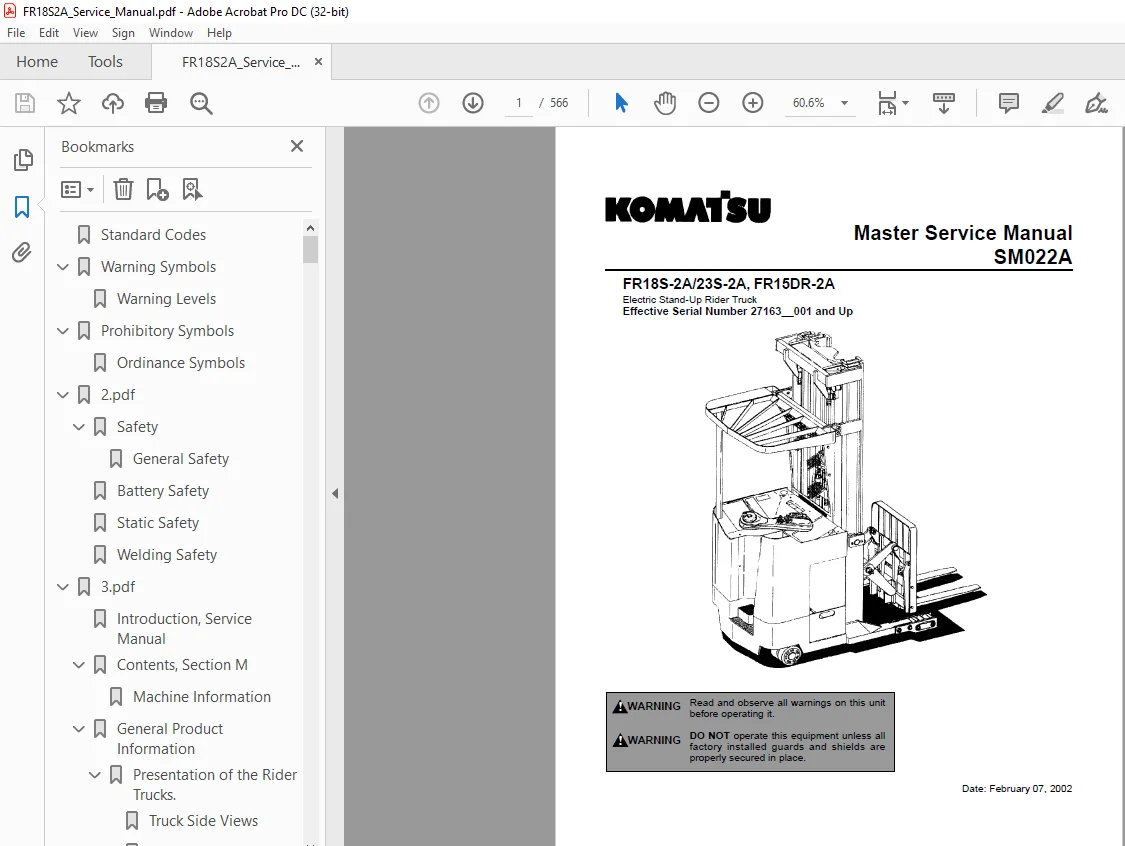
Komatsu Forklift FR18S-2A/23S-2A, FR15DR-2A Master Service Manual SM022A PDF
$30.95
Komatsu Forklift FR18S-2A/23S-2A, FR15DR-2A Master Service Manual SM022A – PDF DOWNLOAD
Electric Stand-Up Rider Truck
Effective Serial Number 27163__001 and Up
Description
Komatsu Forklift FR18S-2A/23S-2A, FR15DR-2A Master Service Manual SM022A – PDF DOWNLOAD
FILE DETAILS:
Komatsu Forklift FR18S-2A/23S-2A, FR15DR-2A Master Service Manual SM022A – PDF DOWNLOAD
Electric Stand-Up Rider Truck
Effective Serial Number 27163__001 and Up
Language :English
Pages :566
Downloadable : Yes
File Type : PDF
IMAGES PREVIEW OF THE MANUAL:
DESCRIPTION:
Komatsu Forklift FR18S-2A/23S-2A, FR15DR-2A Master Service Manual SM022A – PDF DOWNLOAD
Introduction, Service Manual
The information in this Service Manual covers models FR18S/23S-2A and FR15DR-2A. Federal and State laws require that operators be completely trained in the safe operation of trucks in accordance with OSHA regulation 1910.178. An Operator’s Manual is sent with every Komatsu forklift truck when it is manufactured. If the Operator’s Manual is missing from the truck, a new manual may be obtained by contacting
Komatsu Forklift U.S.A., Inc.
14481 Lochridge Blvd., Bldg. 2
Covington, Georgia 300014
(770) 788-3612
This Service Manual is not a training manual. The information contained in this service manual is intended as a guide to help trained, qualified, and authorized technicians safely service the truck. The Service Manual is divided into four separate sections, which cover needed information for servicing the truck types. The main subject for each of the sections are as described below.
TABLE OF CONTENTS:
Komatsu Forklift FR18S-2A/23S-2A, FR15DR-2A Master Service Manual SM022A – PDF DOWNLOAD
Standard Codes 3
Warning Symbols 5
Warning Levels 5
Prohibitory Symbols 6
Ordinance Symbols 6
2pdf 0
Safety 7
General Safety 7
Battery Safety 11
Static Safety 16
Welding Safety 17
3pdf 0
Introduction, Service Manual 19
Contents, Section M 20
Machine Information 20
General Product Information 21
Presentation of the Rider Trucks 21
Truck Side Views 21
Open Back Compartment 22
Intended Truck Application 22
Prohibited Truck Application 23
Truck Data 23
FR18S-2A Dimensions 24
FR23S-2A Dimensions 25
FR15DR-2A Dimensions 26
Data Plate 27
Main Components 28
Inch (SAE) and Metric Fasteners 31
Introduction 31
Nomenclature, Threads 32
Strength Identification 33
Conversion of Metric and English Units 41
4pdf 0
Technical Service Data 43
Ordering Spare Parts 47
Contents, Section P 48
Planned Maintenance 48
Introduction, Maintenance 49
Jacking Truck Off The Floor 50
Lubricants 52
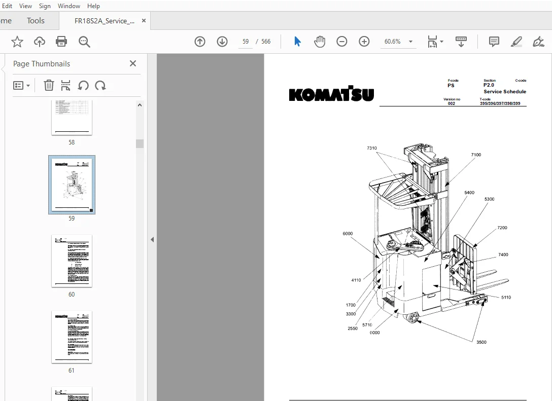
Service Schedule 55
Planned Maintenance Schedule 55
Planned Maintenance Procedures 60
Lubrication Chart 67
Oil and Grease Specifications 68
Approved Oils and Grease 68
Grease Location Points 69
Mast Adjustment Points 70
5pdf 0
Contents, Section S 71
Service Instructions 71
Troubleshooting Guidelines 72
General 72
Electrical 74
Hydraulic 79
Definitions 80
Chassis 82
General 82
Dash 83
Motor Compartment Door 84
Left-Hand Side Panel 85
Operator Compartment Panel 86
Main Card Access Panel 86
Battery Compartment 87
Battery Retainer Plates 88
Battery Rollers 88
6pdf 0
Driver Controls 89
Brake Pedal, FR18S-2A 90
Pedal Removal 91
Pedal Bearing Replacement 92
Pedal Adjustment 92
Brake Pedal, FR23S-2A/ FRD15DR-2A 93
Pedal Removal 94
Pedal Bearing Replacement 95
Pedal Adjustment 95
7pdf 0
Overhead Guard 96
7pdf 0
Overhead Guard 98
8pdf 0
Decals100
Decal with Protective Sheet100
Decal without Protective Sheet100
9pdf 0
Steering Motor103
Removal103
Installation103
Steering Motor Gear Replacement104
Fan Motor105
Upper Electrical Compartment Fan105
Operator Fan106
Motor Maintenance Schedule/Troubleshooting107
General Information107
Operating Conditions107
Troubleshooting108
Motor Repair115
Disassembly115
Motor Inspection117
Pump Motor123
Mounting Points123
Repair127
Drive Motor130
Mounting Points130
Repair133
Transmission135
Mounting Points135
Repair139
Disassemble141
Assembly145
Axle Sealing Ring154
Leakage156
Wheel Bolt158
91pdf 0
Electromagnetic Brake159
Removal159
Installation161
Adjustments162
Coil Check On Brake163
Electromagnetic Brake, Armature and Magnetic Coil163
Brake Friction Plate164
Drive Wheel165
Removal166
Installation166
Tire Pressing Procedure167
Non-Braking Caster Wheel, FR18S-2A169
Caster Pivot171
Thrust Bearing173
Caster Springs175
Caster Stops177
Non-Braking Caster Assembly, FR18S-2A178
Removal179
Installation179
Braking Caster Wheel, FR23S-2A/ FR15DR-2A180
Removal182
Braking Caster Assembly, FR23S-2A/ FR15DR-2A184
Removal186
Installation187
Load Wheels, Sizes 4 X 3, 5 X 4, and 5 X 3188
Removal190
Installation191
Load Wheels, Size 105 X 35192
Removal193
Installation193
Steering Arm / Wheel / Lever194
Control Pod196
Steering Wheel197
Steering Tach198
Steering Bearing199
Removal200
Installation200
92pdf 0
Electrical Functions201
General201
Start Up205
Steering Components209
Brake Release215
Direction Selection217
Travel Request, Forks First219
Travel Request, Forks Trailing223
Plug Braking228
12-Volt Power Supply232
735-Volt Power Supplies233
Limit Switches236
Height Indicator240
Drive Motor Brush Wear Indicator Switches242
Pump Motor Brush Indicator Switch243
Safety Check244
Shunt Power Cable246
Electrical Symbols253
93pdf 0
Electrical Schematics (Serial Numbers 27163__000 – 28105__000)255
Circuit Diagram 1(11)255
Circuit Diagram 2(11)256
Circuit Diagram 3(11)257
Circuit Diagram 4(11)258
Circuit Diagram 5(11)259
Circuit Diagram 6(11)260
Circuit Diagram 7(11)261
Circuit Diagram 8(11)262
Circuit Diagram 9(11)263
Circuit Diagram 10(11)264
Circuit Diagram 11(11)265
94pdf 0
Electrical Schematics (Serial Numbers 28105__001-28126__000)266
Circuit Diagram 1(12)266
Circuit Diagram 2(12)267
Circuit Diagram 3(12)268
Circuit Diagram 4(12)269
Circuit Diagram 5(12)270
Circuit Diagram 6(12)271
Circuit Diagram 7(12)272
Circuit Diagram 8(12)273
Circuit Diagram 9(12)274
Circuit Diagram 10(12)275
Circuit Diagram 11(12)276
Circuit Diagram 12(12)277
95pdf 0
Electrical Schematics (Serial Numbers 28126__001 – 31285__000)278
Circuit Diagram 1(12)278
Circuit Diagram 2(12)279
Circuit Diagram 3(12)280
Circuit Diagram 4(12)281
Circuit Diagram 5(12)282
Circuit Diagram 6(12)283
Circuit Diagram 7(12)284
Circuit Diagram 8(12)285
Circuit Diagram 9(12)286
Circuit Diagram 10(12)287
Circuit Diagram 11(12)288
Circuit Diagram 12(12)289
96pdf 0
Electrical Schematics (Serial numbers 31285__001-Up)290
Circuit Diagram 1(12)290
Circuit Diagram 2(12)291
Circuit Diagram 3(12)292
Circuit Diagram 4(12)293
Circuit Diagram 5(12)294
Circuit Diagram 6(12)295
Circuit Diagram 7(12)296
Circuit Diagram 8(12)297
Circuit Diagram 9(12)298
Circuit Diagram 10(12)299
Circuit Diagram 11(12)300
Circuit Diagram 12(12)301
97pdf 0
Battery302
Removal302
Installation302
Battery Maintenance303
Storage305
Battery History Record305
Light Assemblies306
Overhead Guard Lights (Option)306
Warning Lights (Option)307
Working Lights (Option)308
Travel Alarm (Option)309
Operator Fan (Option)310
Horn312
Removal312
Installation312
Start/Stop Switches313
General313
Key Switch (S17)313
Emergency Disconnect Switch315
Battery Connector317
Location317
Inspection317
Installation318
Mast Switch (S31)319
General319
98pdf 0
Control Cable and Harness323
Fuses323
Wiring324
Contactors326
General326
Direction Contactors327
Lift Bypass Contactor (FR23S-2A/FR15DR-2A)329
Main Contactor331
Transistor Panel (Drive)333
Motor Connections334
Transistor Panel (Lift)335
Circuit Check, Drive Only337
Micro Switches338
General338
Lift Limit Override Switch (S33) Optional339
Optional Light and Fan Switches (S96, S97 and S99)340
Main Electronic Card341
Connectivity to Truck341
Transistor Controller Replacement342
Removal346
Installation346
Display352
Time353
Effect on Truck353
Running time354
RV2 Adjustment Procedure354
Adjustment Procedures for Setting Brake Switch and Brake Transducer355
Battery Discharge Indicator Parameter Adjustment356
A5 Jumper Harness Kit Installation (Serial numbers 2812600000 – below)362
Warning\Caution Codes365
Error Codes367
Programming Parameter373
Switches and Sensors383
General383
Platform (Right Foot) Switch (S108)383
Staging Switch (S45)385
Wheel Direction Sensor387
Steer Proximity Sensors A and B (S66 and S67)389
Drive Motor Speed (S64)/Direction Sensors (S125)391
99pdf 0
Hydraulic System393
Operation393
Supply395
Lifting396
Lowering397
Reach399
Retract401
Reach Relief (FR18S-2A Only)402
Reach Impact (FR18S-2A Only)403
Tilt Up405
Tilt Down407
Side Shifting Right409
Side Shifting Left411
FR18S-2A Hydraulic Schematic414
FR23S-2A Hydraulic Schematic415
FR15DR-2A Hydraulic Schematic416
Hydraulic Fluid417
Hydraulic Fluid Selection417
Changing Hydraulic System Fluid417
System Draining418
Refilling System419
Bleeding Hydraulic System420
Hydraulic Tank422
Removal423
Installation424
Hydraulic Filter Assembly425
Hydraulic Filter426
Hydraulic Filter Adapter427
Hydraulic Pump428
Removal428
Repair428
Control Valve429
Removal429
Installation429
Control Valve Assembly434
Repair436
991pdf 0
Staging Cylinder, Three Stage Mast440
Bearing Removal441
Disassembly442
Assembly442
Installation442
Freelift Cylinder, Three Stage Mast443
Removal445
Disassembly446
Assembly446
Installation446
Reach Cylinder Assembly447
Removal449
Disassembly450
Inspection451
Assembly452
Installation453
Tilt Cylinder Assembly, FR18S-2A454
Removal455
Disassembly456
Inspection457
Assembly458
Installation459
Tilt Cylinder Assembly, FR23S-2A/FR15DR-2A460
Removal462
Disassembly463
Inspection464
Assembly465
Installation466
992pdf 0
Mast, 3 Stage467
Shimming Carriage with Mast on Truck471
Three Stage Mast473
Lift Chain478
Lifting Gear (Crosshead)486
Lifting Gear Repair488
Sideshifter, FR18S/23S-2A, FR15DR-2A490
Mounting Instructions492
Operation and Maintenance493
Sideshifter, FR18S/23S-2A, FR15DR-2A495
Mounting Instructions497
Operation498
Maintenance498
Troubleshooting502
Single Reach, FR18S-2A503
Maintenance509
Reach Repair514
Carriage Bumpers518
Fork Carriage Pivot Pins520
Carriage Roller Bearings520
Single Reach, FR23S-2A521
Maintenance521
Reach Repair529
Fork Carriage Pivot Pins533
Carriage Roller Bearings534
Double Reach Mechanism, FR15DR-2A535
Theory of Operation537
Maintenance537
Troubleshooting537
Repair537
Rebuild537
Forks538
Removal540
Inspection540
Installation541
Load Indicator FR18S-2A542
Load Indicator FR23S-2A/FR1 5DR-2A544
Pulse Sensor546
Height Indicator and Preset Selector548
General549
Operation549
Preset Height550
Display551
Display Symbols Description552
Programming553
Load Backrest562
Removal565
Installation565
S.M 25/1/25