Komatsu DUMP TRUCK HD465-7R Shop Manual SEN06285-03 – PDF DOWNLOAD
$34.95
Komatsu DUMP TRUCK HD465-7R Shop Manual SEN06285-03 – PDF DOWNLOAD’
SERIAL NUMBERS 16132 and up
Description
Komatsu DUMP TRUCK HD465-7R Shop Manual SEN06285-03 – PDF DOWNLOAD
FILE DETAILS:
Komatsu DUMP TRUCK HD465-7R Shop Manual SEN06285-03 – PDF DOWNLOAD
Language : English
Pages :1650
Downloadable : Yes
File Type : PDF
IMAGES PREVIEW OF THE MANUAL:
DESCRIPTION:
Komatsu DUMP TRUCK HD465-7R Shop Manual SEN06285-03 – PDF DOWNLOAD
SERIAL NUMBERS 16132 and up
SERIAL NUMBERS 90001 and up
How to Read the Shop Manual
• Some of the attachments and options described in this shop manual may not be available in some areas. If
they are required, consult your Komatsu distributor.
• The materials and specifications are subject to change without notice.
• Shop Manuals are available for “machine part” and “engine part”. For the engine unit, see the shop manual
for the machine which has the same engine model.
• Actual machine may differ from the images which are contained in this manual. A typical model is shown in
the illustrations of this shop manual.
• The caution lamps, pilot lamps, and symbols of the switches on the machine monitor can be different in
accordance with the machine.
• For details of the symbols shown on the machine monitor, see Structure and Operation, “Caution
Lamps Shown on Machine Monitor” and “Pilot Lamps Shown on Machine Monitor”.
• For details of the switches of the machine monitor, see Testing and Adjusting, “Set and Operate Machine
Monitor”.
• For details of the switches, see the “Operation and Maintenance Manual”.
• All “AdBlue/DEF” shown on the machine monitor is referred to as “DEF” in the shop manual. Some machine
monitors installed to the product show “DEF” as “AdBlue/DEF” in the service mode. Thus, be sure to recognize
that “DEF” and “AdBlue/DEF” are the same when you read the shop manual.
REMARK
The illustrations in the shop manual reproduce the display of the machine monitor. They are not always the
same as the terminology in the shop manual.
Composition of the Shop Manual
This shop manual contains technical information necessary to perform services in workshops. It is divided into
the following chapters for the ease of use.
00 Index and Foreword
This section describes the index, foreword, safety, and basic information.
01 Specification
This section describes the specifications of the machine.
10 Structure and Function
This section describes the structure and operation of each component with respect to each system. “Structure
and Function” is helpful in not only understanding the structure of each component but performing troubleshooting.
20 Standard Value Table
This section describes the standard values for new machine and failure criteria for testing and adjusting, and
troubleshooting. Use the standard values table to check the standard values for testing and adjusting, and judge
troubles in troubleshooting.
30 Testing and Adjusting
This section describes the measuring tools and measuring methods for testing and adjusting as well as the adjusting
method of each part. The standard values and repair limit for TESTING AND ADJUSTING are described
in “Standard Value Table”.
40 Troubleshooting
This section describes troubleshooting of failure part and its remedy method on the occurrence of the failure.
Descriptions of troubleshooting are sorted by failure mode.
This section describes the special tools, work procedures, and safety precautions necessary for removal, installation,
disassembly, and assembly of the components and parts. In addition, tightening torques, quantity, and
weight of the coating materials, lubricants, and coolant necessary to these works are shown.
60 Maintenance Standard
This section describes the maintenance standard value of each component. The maintenance standard shows
the criteria and remedies for disassembly and assembly.
80 Others
This section describes the structure and function, testing and adjusting, and troubleshooting for all of the other
components or equipment which cannot be separately classified in the appendix.
90 Circuit Diagrams
This section describes hydraulic circuit diagrams and electrical circuit diagrams.
Symbols
Important safety and quality portions are marked with the following symbols so that shop manual is used effectively.
TABLE OF CONTENTS:
Komatsu DUMP TRUCK HD465-7R Shop Manual SEN06285-03 – PDF DOWNLOAD
SERIAL NUMBERS 16132 and up
Cover 1
00 Index and foreword 0
Index 3
Composition of shop manual 4
Table of contents 6
Foreword and general information 21
Safety notice 22
How to read the shop manual 27
Explanation of terms for maintenance standard 29
Handling of electric equipment and hydraulic component 31
Handling of connectors newly used for engines 40
How to read electric wire code 43
Precautions when carrying out operation 46
Method of disassembling and connecting push-pull type coupler 49
Standard tightening torque table 52
Conversion table 56
01 Specification 0
Specification and technical data 63
Specification drawing 64
Specifications 65
Weight table 68
Fuel, coolant and lubricants 69
10 Structure, function and maintenance standard 0
Engine and cooling system 73
Radiator, torque converter oil cooler, after cooler, work equipment oil cooler, fuel cooler 74
Fuel system 76
Brake oil cooler 77
Output shaft 78
Power train, Part 1 81
Power train skeleton 82
Drive shaft 84
Torque converter and transmission hydraulic piping 86
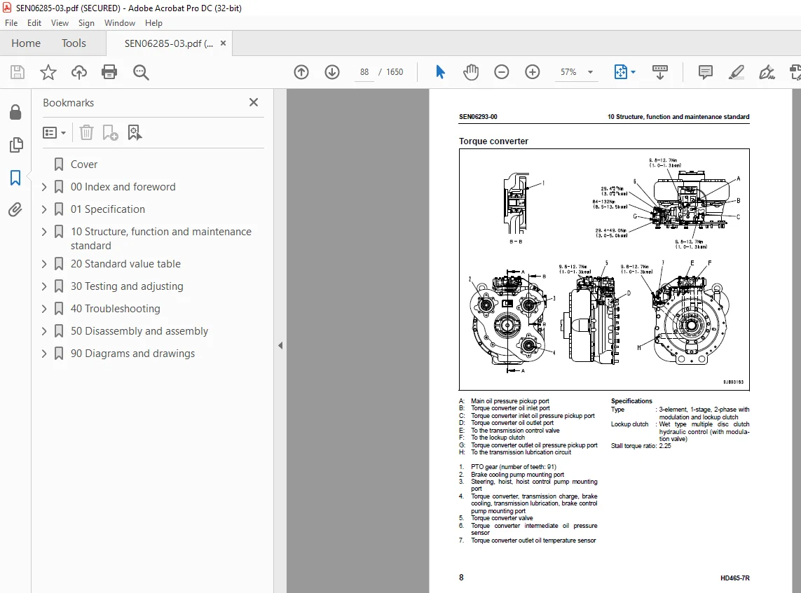
Torque converter 88
Torque converter valve 95
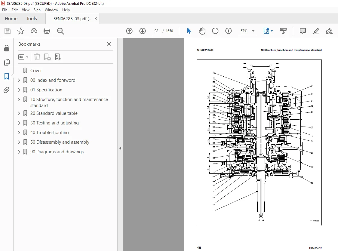
Transmission 97
Transmission control valve 113
ECMV 114
Power train, Part 2 123
Axle 124
Differential 126
Final drive 127
Wheels 128
Steering system 131
Steering column 132
Steering linkage 133
Brake system 137
Brake piping 138
Brake valve 140
Secondary brake valve 143
Relay valve 144
Front brake off valve 145
Accumulator charge valve 146
Accumulator 150
Slack adjuster 151
Brake 153
Parking brake solenoid valve 157
Undercarriage and frame 159
Suspension 160
Suspension cylinder 162
Rear axle support 168
Hydraulic system 171
Steering and hoist hydraulic piping 172
Dump body control 174
Hydraulic tank 175
Steering valve 176
Crossover relief valve 180
Steering cylinder 181
Steering control valve 182
Hoist valve 188
EPC valve 194
Hoist cylinder 195
Hydraulic pump 196
Work equipment (Body) 201
Auto greasing system 202
Cab and its attachments 225
Air conditioner 226
Rear view monitor 232
Electrical system, Part 1 241
Machine monitor system 242
Electrical system, Part 2 303
Automatic shift control system 304
Transmission controller 308
External power supply heater 322
Automatic emergency steering system 324
Automatic suspension system 328
Retarder control system 331
Battery disconnect switch 342
Dump control lever 346
Electrical system, Part 3 351
Payload meter II (Card type) 352
Electrical system, Part 4 383
VHMS controller related 384
ASR system (If equipped) 408
Sensors, switches 415
20 Standard value table 0
Standard service value table 435
Standard value table for engine 436
Standard value table for machine 438
30 Testing and adjusting 0
Testing and adjusting, Part 1 449
Tools for testing, adjusting, and troubleshooting 451
Sketch of special tool 454
Testing engine speed 455
Testing air supply pressure (boost pressure) 456
Testing exhaust temperature 457
Testing exhaust gas color 459
Testing engine oil pressure 467
Handling of fuel system devices 468
Releasing residual pressure from fuel system 468
Testing of fuel pressure 469
Cylinder cut-out mode operation 470
No-injection cranking 470
Testing of fuel return rate and fuel leakage 471
Bleeding air from fuel circuit 473
Testing the fuel circuit for leakage 474
Adjustment of valve clearance 461
Testing of compression pressure 463
Testing blow-by pressure 466
Replacing and adjusting of fan belt 475
Replacing and adjusting of alternator and air conditioner compressor belt 476
Testing and adjusting, Part 2 479
Testing torque converter stallspeed 481
Testing power train oil pressure 482
Adjusting transmission speed sensor 489
Testing and adjusting brake oilpressure 490
Testing of accumulator nitrogengas pressure and procedure forcharging accumulator with nitrogengas 493
Testing brake performance 501
Releasing remaining pressure inbrake circuit 502
Bleeding air from brake circuit 503
Testing wear of front brake pad 504
Testing wear of rear brake disc 505
Method of releasing parking brakein an emergency 506
Testing and adjusting frontsuspension cylinder 507
Testing and adjusting rearsuspension cylinder 511
Testing and adjusting frontsuspension cylinder(Automatic suspension specification) 515
Testing and adjusting hydraulicpressure in steering, hoist circuit1 516
Testing and adjusting oil pressurein dump EPC circuit 519
Air bleeding from steeringcylinder 520
Procedure for raising dump bodyin emergency 521
Procedure for lowering dumpbody in emergency 522
Adjusting body positioner sensor1 524
Resetting method for dump bodyseating control 525
Adjustment of tilt lock lever ofsteering wheel 526
Handling of voltage circuit ofengine controller 527
Adjusting transmissioncontroller 527
Method for emergency escape at electrical system failure 528
Testing and adjusting, Part 3 533
Setting and adjusting of devices 534
Special functions of machine monitor (EMMS) 547
Testing and adjusting, Part 4 571
Special functions of machine monitor (EMMS) 572
Testing and adjusting, Part 5 613
Request for opening ORBCOMM terminal 614
VHMS controller initial setting procedure 616
Using method of KOMTRAX functions of ORBCOMM terminal 636
Precautions for replacing VHMS controller 639
Pm Clinic check sheet 645
Initial setting of payload meter 648
Setting of payload meter built in VHMS 649
Setting of card-type payload meter (PLM-) after installation or replacement 657
40 Troubleshooting 0
Failure code table and fuse locations 665
Failure codes table 666
Fuse locations 677
General information on troubleshooting 683
Points to remember when troubleshooting 684
Sequence of events in troubleshooting 685
Check before troubleshooting 686
Classification and procedures for troubleshooting 687
Contents of troubleshooting table 688
Troubleshooting method for disconnecting wiring harness of pressure sensor system 690
Connection table for connector pin numbers 693
T- branch box and T- branch adapter table 729
Troubleshooting by failure code, Part 1 733
Failure code [1500L0] Dual engagement 735
Failure code [15B0NX] Transmission oil filter: Clogging 736
Failure code [15F0KM] R → F shifting abuse 1: Mistake in operation 738
Failure code [15F0MB] R → F shifting abuse 2: Mistake in operation 738
Failure code [15F7KM] Forward clutch disk abuse: Mistake in operation or setting 739
Failure code [15G0MW] R clutch: Slipping 740
Failure code [15G7KM] Reverse clutch disk abuse: Mistake in operation or setting 742
Failure code [15H0MW] Hi clutch: Slipping 744
Failure code [15J0MW] Lo clutch: Slipping 746
Failure code [15K0MW] 1st clutch: Slipping 748
Failure code [15L0MW] 2nd clutch: Slipping 750
Failure code [15M0MW] 3rd clutch: Slipping 752
Failure code [15N0MW] 4th clutch: Slipping 754
Failure code [15SBL1] R clutch solenoid: Fill signal is ON when command current is OFF 756
Failure code [15SBMA] R clutch solenoid: Malfunction 758
Failure code [15SCL1] Hi clutch solenoid: Fill signal is ON when command current is OFF 759
Failure code [15SCMA] Hi clutch solenoid: Malfunction 762
Failure code [15SDL1] Lo clutch solenoid: Fill signal is ON when command current is OFF 763
Failure code [15SDMA] Lo clutch solenoid: Malfunction 766
Failure code [15SEL1] 1st clutch solenoid: Fill signal is ON when command current is OFF 767
Failure code [15SEMA] 1st clutch solenoid: Malfunction 770
Troubleshooting by failure code, Part 2 773
Failure code [15SFL1] 2nd clutch solenoid: Fill signal is ON when command current is OFF 776
Failure code [15SFMA] 2nd clutch solenoid: Malfunction 779
Failure code [15SGL1] 3rd clutch solenoid: Fill signal is ON when command current is OFF 780
Failure code [15SGMA] 3rd clutch solenoid: Malfunction 783
Failure code [15SHL1] 4th clutch solenoid: Fill signal is ON when command current is OFF 784
Failure code [15SHMA] 4th clutch solenoid: Malfunction 787
Failure code [15SJMA] Lockup clutch solenoid: Malfunction 788
Failure code [2C4MNX] Retarder cooling oil filter: Clogging 790
Failure code [2F00KM] Parking brake: Mistake in operation or setting 792
Failure code [2G42ZG] Accumulator: Oil pressure reduction (Front) 795
Failure code [2G43ZG] Accumulator: Oil pressure reduction (Rear) 795
Failure code [6014NX] Hydraulic oil filter: Clogging 796
Failure code [989A00] Engine over run prevention command signal: Operating 798
Failure code [989D00] Rear section tipping over alarm: Alarm is activated 798
Failure code [A570NX] Engine oil filter: Clogging 799
Failure code [AA10NX] Air cleaner element: Clogging 800
Failure code [AB00MA] Alternator: Malfunction 802
Failure code [B@BAZG] Abnormal lowering of engine oil pressure: Lowering of oil pressure 804
Failure code [B@BAZK] Engine oil: Level too low 805
Failure code [B@BCNS] Engine: Overheat 806
Failure code [B@BCZK] Lowering of radiator coolant: Lowering of level 808
Failure code [B@BFZK] Lowering of fuel level 810
Failure code [B@C7NS] Brake cooling oil: Overheating (Rear) 812
Failure code [B@CENS] Overheating of torque converter oil 814
Failure code [B@GAZK] Battery electrolyte level: Lowering of level 815
Failure code [B@JANS] Steering oil temperature: Overheat 816
Troubleshooting by failure code, Part 3 819
Failure code [CA111] Abnormality in engine controller 822
Failure code [CA115] Engine Ne or Bkup speed sensor error 824
Failure code [CA122] Charge (boost) pressure sensor high error 826
Failure code [CA123] Charge (boost) pressure sensor low error 828
Failure code [CA131] Throttle sensor high error 830
Failure code [CA132] Throttle sensor low error 833
Failure code [CA135] Engine oil pressure sensor high error 836
Failure code [CA141] Engine oil pressure sensor low error 838
Failure code [CA144] Coolant temperature sensor high error 840
Failure code [CA145] Coolant temperature sensor low error 842
Failure code [CA153] Charge (boost) temperature sensor high error 844
Failure code [CA154] Charge (boost) temperature sensor low error 846
Failure code [CA187] Sensor power supply 2 low error 848
Failure code [CA212] Engine oil temperature sensor high error 850
Failure code [CA213] Engine oil temperature sensor low error 852
Failure code [CA221] Atmospheric pressure sensor high error 854
Failure code [CA222] Atmospheric pressure sensor low error 856
Failure code [CA227] Sensor power supply 2 high error 858
Failure code [CA234] Engine overspeed 859
Failure code [CA238] Ne speed sensor power supply error 860
Failure code [CA263] Fuel Temp Sensor High Error 862
Failure code [CA265] Fuel Temp Sensor Low Error 864
Failure code [CA271] PCV1 Short circuit 866
Failure code [CA272] PCV1 Disconnection 867
Failure code [CA273] PCV2 Short circuit 868
Failure code [CA274] PCV2 Disconnection 869
Failure code [CA322] Injector #1 open/short error 870
Failure code [CA323] Injector #5 open/short error 872
Failure code [CA324] Injector #3 open/short error 874
Failure code [CA325] Injector #6 open/short error 876
Failure code [CA331] Injector #2 open/short error 878
Failure code [CA332] Injector #4 open/short error 880
Failure code [CA342] Calibration code inconsistency 882
Failure code [CA351] Injectors drive circuit error 883
Failure code [CA352] Sensor power supply 1 low error 884
Failure code [CA386] Sensor power supply 1 high error 886
Troubleshooting by failure code, Part 4 889
Failure code [CA431] Idle validation switch error 891
Failure code [CA432] Idle validation action error 894
Failure code [CA441] Battery voltage low error 897
Failure code [CA442] Battery voltage high error 898
Failure code [CA449] Common rail pressure high error 2 899
Failure code [CA451] Rail Press Sensor High Error 900
Failure code [CA452] Rail Press Sensor Low Error 902
Failure code [CA553] Common rail pressure high error 1 904
Failure code [CA554] Common rail pressure sensor in range error 905
Failure code [CA559] Supply pump pressure very low error 1 906
Failure code [CA689] Engine Ne speed sensor error 910
Failure code [CA731] Engine Bkup speed sensor phase error 912
Failure code [CA757] All continuous data lost error 913
Failure code [CA778] Engine Bkup speed sensor error 914
Failure code [CA1633] KOMNET datalink timeout error 916
Failure code [CA2185] Throttle sensor power supply voltage high error 918
Failure code [CA2186] Throttle sensor power supply voltage low error 920
Failure code [CA2249] Supply pump pressure very low error 2 922
Failure code [CA2555] Intake air heater relay open circuit error 924
Failure code [CA2556] Intake air heater relay short circuit error 926
Troubleshooting by failure code, Part 5 929
Failure code [D19HKB] Stop lamp relay output system: Short circuit 931
Failure code [D5ZKKZ] Front brake cut-off solenoid valve: Disconnection, short circuit or short circuit to power supply line 932
Failure code [DAF9KM] Wrong connection of connector 934
Failure code [DAFRKR] Abnormal CAN communication (machine monitor): Abnormal communication 935
Failure code [DAQ0KK] Transmission controller direct power supply: Lowering of power supply voltage 936
Failure code [DAQ0KT] Transmission controller nonvolatile memory: Abnormality in controller 938
Failure code [DAQ2KK] Transmission controller solenoid power supply: Power supply voltage too low 940
Failure code [DAQ9KQ] Transmission controller: Disagreement of model selection 942
Failure code [DAQRKR] Abnormality in CAN communication (Transmission) 943
Failure code [DAQRMA] Transmission controller option setting: Malfunction 948
Failure code [DAQV00] Neutral coast caution 949
Failure code [DAQW00] Neutral over speed caution 950
Failure code [DB10KT] Retarder controller nonvolatile memory: Abnormality in controller 951
Failure code [DB12KK] Retarder controller solenoid power supply: Power supply system trouble 952
Failure code [DB13KK] Retarder controller battery direct power supply: Power supply voltage too low 954
Failure code [DB19KQ] Disagreement of model selection (Retarder controller) 956
Failure code [DB1RKR] CAN communication (retarder controller): Communication disabled 957
Failure code [DB1RMA] Disagreement of option setting (Retarder controller) 961
Failure code [DB2RKR] CAN communication (engine controller): Communication disabled 962
Failure code [DBB0KK] or VHMS_LED display: “n9” → “01” 968
Failure code [DBB0KQ] or VHMS_LED display: “nF” → “11” 970
Failure code [DBB3KK] or VHMS_LED display: “n9” → “05” 972
Failure code [DBB5KP] or VHMS_LED display: “n9” → “04” 974
Failure code [DBB6KP] or VHMS_LED display: “n9” → “02” 976
Failure code [DBB7KP] or VHMS_LED display: “n9” → “03” 978
Failure code [DBBQKR] or VHMS_LED display: “n8” → “02” 979
Failure code [DBBRKR] Abnormality in CAN communication (VHMS) 979
Failure code [DBC2KK] ABS controller solenoid power supply: Power supply system trouble 980
Failure code [DBC3KK] ABS controller battery direct power supply: Power supply voltage too low 982
Failure code [DBC9KQ] Disagreement of model selection (ABS controller) 984
Failure code [DBCRKR] Abnormality in CAN communication (ABS) 985
Failure code [DBCRMA] Disagreement of option setting (ABS controller) 989
Failure code [DDD7KX] Trouble in travel speed setting switch system: Out of input signal range 990
Failure code [DDD8KA] ARSC system switch system: Disconnection (If equipped) 992
Failure code [DDD8KB] ARSC system switch system: Short circuit (If equipped) 994
Failure code [DDD9KA] ABS system switch system: Disconnection 996
Failure code [DDD9KB] ABS system switch system: Short circuit 998
Failure code [DDDAKA] ASR system switch: Disconnection1000
Failure code [DDDAKB] ASR system switch: Short circuit1002
Failure code [DDP6L4] Service brake pressure switch trouble (Rear)1004
Failure code [DDTHKA] Hi clutch fill switch: Disconnection1006
Failure code [DDTJKA] Lo clutch fill switch: Disconnection1008
Failure code [DDTKKA] 1st clutch fill switch: Disconnection1010
Failure code [DDTLKA] 2nd clutch fill switch: Disconnection1012
Failure code [DDTMKA] (3rd clutch fill switch: Disconnection)1014
Failure code [DDTNKA] R clutch fill switch: Disconnection1016
Failure code [DDTPKA] 4th clutch fill switch: Disconnection1018
Failure code [DF10KA] Gear shift lever: Disconnection1020
Failure code [DF10KB] Gear shift lever: Short circuit1023
Failure code [DGE5KX] or VHMS_LED display: “n4” → “01”1028
Failure code [DGF1KX] Transmission oil temperature sensor: Out of input signal range1030
Failure code [DGR2KZ] Retarder oil temperature sensor system trouble : Ground fault (Rear wheel)1032
Failure code [DGR6KX] Steering oil temperature sensor: Input signal out of range1034
Failure code [DGT1KX] Torque converter oil temperature sensor: Out of input signal range1036
Troubleshooting by failure code, Part 61039
Failure code [DGT4KA] or VHMS_LED display: “n3” -> “12” Exhaust gastemperature sensor (F): Disconnection1041
Failure code [DGT4KB] or VHMS_LED display: “n3” -> “11” Exhaust gastemperature sensor (F): Short circuit1044
Failure code [DGT5KA] or VHMS_LED display: “n3” -> “22” Exhaust gastemperature sensor (R): Disconnection1047
Failure code [DGT5KB] or VHMS_LED display: “n3” -> “21” Exhaust gastemperature sensor (R): Short circuit1050
Failure code [DHE5KB] or VHMS_LED display: “n3” -> “32” Blow-bypressure sensor: Short circuit1053
Failure code [DHE5KY] or VHMS_LED display: “n3” -> “31” Blow-by pressure sensor: Short circuit with power supply line1056
Failure code [DHP4KY] or VHMS_LED display: “n5” -> “44” Short circuit in suspension pressure sensor system (Front right)1058
Failure code [DHP4KZ] or VHMS_LED display: “n5” -> “43” Disconnectionor ground fault in suspension pressure sensor system(Front right)11060
Failure code [DHP5KY] or VHMS_LED display: “n5” -> “54” Short circuit in suspension pressure sensor system (Front left)1062
Failure code [DHP5KZ] or VHMS_LED display: “n5” -> “53” Disconnectionor ground fault in suspension pressure sensor system(Front left)1064
Failure code [DHP6KA] Suspension pressure sensor system: Disconnection (Right rear)1066
Failure code [DHP6KX] Failure in suspension pressure sensor system trouble: Out of input signal range (Right rear)1067
Failure code [DHP6KY] or VHMS_LED display: “n5” -> “64” Suspensionpressure sensor system: Short circuit (Right rear)1070
Failure code [DHP6KZ] or VHMS_LED display: “n5” -> “63” Suspension pressure sensor system: Disconnection or ground fault (Right rear)1072
Failure code [DHP7KA] Suspension pressure sensor system: Disconnection (Left rear)1074
Failure code [DHP7KX] Failure in suspension pressure sensor system trouble: Out of input signal range (Left rear)1076
Failure code [DHP7KY] or VHMS_LED display: “n5” -> “74” Suspension pressure sensor system: Short circuit (Left rear)1078
Failure code [DHP7KZ] or VHMS_LED display: “n5” -> “73” Suspension pressure sensor system: Disconnection or ground fault (Left rear)1080
Failure code [DHT5KX] Torque converter oil pressure sensor: Out of input signal range1082
Failure code [DHT5L6] Torque converter oil pressure sensor: Disagreement of run and stop condition with signal1084
Failure code [DHU2KX] Front accumulator oil pressure sensor: Out of input signal range1086
Failure code [DHU3KX] Rear accumulator oil pressure sensor: Out of input signal range1088
Failure code [DHU6KX] Trouble in ABS control valve pressure sensor (Front right)1090
Failure code [DHU7KX] Trouble in ABS control valve pressure sensor (Front left)1092
Failure code [DHU8KX] Trouble in ABS control valve pressure sensor (Front right)1094
Failure code [DHU9KX] Trouble in ABS control valve pressure sensor (Front right)1096
Failure code [DJF1KA] Fuel level sensor: Disconnection1098
Failure code [DK30KX] Steering angle potentiometer: Trouble (Disconnection)1100
Failure code [DK51L5] Retarder lever potentiometer: Potentiometer signal is inconsistent with swich signal1101
Failure code [DK52KX] Failure in hoist lever potentiometer 1: Out of input signal range1104
Failure code [DK53L8] Failure in hoist lever potentiometer 2: Disagreement of analog signal1106
Failure code [DK54KX] Body positioner sensor: Out of input signal range1108
Failure code [DKD0L6] Failure in steering speed sensor1110
Failure code [DKH0KX] Clinometer sensor signal out of range1112
Failure code [DKH1KX] or VHMS_LED display: “n4″->”33” Abnormality in clinometer sensor1114
Failure code [DLF1KA] Transmission input shaft speed sensor: Disconnection1116
Failure code [DLF1LC] Transmission input shaft speed sensor: Disagreement of revolution speed signal1118
Failure code [DLF2KA] Transmission intermediate shaft speed sensor: Disconnection1120
Failure code [DLF2LC] Transmission intermediate shaft speed sensor: Disagreement of revolution speed signal1122
Troubleshooting by failure code, Part 71125
Failure code [DLF8KA] (Wheel speed sensor: Disconnection (Right rear))1128
Failure code [DLF8L3] (Wheel speed sensor: Disconnection (Right rear))1130
Failure code [DLF8LC] (Wheel speed sensor: Trouble (Right rear))1132
Failure code [DLF8MA] (Wheel speed sensor: Disconnection (Right rear))1133
Failure code [DLF9KA] (Wheel speed sensor: Disconnection (Left rear))1134
Failure code [DLF9L3] (Wheel speed sensor: Trouble (Left rear))1136
Failure code [DLF9LC] (Wheel speed sensor: Trouble (Left rear))1138
Failure code [DLF9MA] (Wheel speed sensor: Disconnection (Left rear))1139
Failure code [DLT3KA] (Transmission output shaft speed sensor: Disconnection)1140
Failure code [DLT3LC] (Transmission output shaft speed sensor: Disagreement of revolution speed signal)1142
Failure code [DLT4KA] (Transmission output shaft speed sensor: Disconnection)1144
Failure code [DLT4MA] (Transmission output shaft speed sensor: Malfunction)1146
Failure code [DV00KB] (Buzzer output: Short circuit)1148
Failure code [DW2AKA] (Main pressure variable valve output: Disconnection)1150
Failure code [DW2AKB] (Main pressure variable valve output circuit: Ground fault)1152
Failure code [DW2AKY] (Main pressure variable valve output circuit: Hot short)1154
Failure code [DW2AL1] (Main pressure variable valve: Defective reset) 1156
Failure code [DW2ALH] (Main pressure variable valve: Malfunction)1158
Failure code [DW35KZ] (Failure in output system of auto suspension solenoid 1: Disconnection or short circuit)1160
Failure code [DW36KZ] (Failure in output system of auto suspension solenoid 2: Disconnection or short circuit) (If equipped)1162
Failure code [DW72KZ] (Kick-out solenoid output system trouble: Disconnection or short circuit)1164
Failure code [DW73KZ] (Failure in hoist select valve output system: Disconnection or short circuit)1166
Failure code [DW78KZ] (Brake cooling valve (BCV) (rear wheel) output system trouble: Disconnection or short circuit)1168
Failure code [DWNBK4] (ASR shut-off valve: Trouble (Valve keeps operating))1170
Failure code [DWNBKA] (ASR shut-off valve output circuit: Disconnection)1172
Failure code [DWNBKB] (ASR shut-off valve output circuit: Ground fault)1174
Failure code [DWNBKY] (ASR shut-off valve output circuit: Short circuit)1176
Failure code [DWNBMA] (ASR shut-off valve: Trouble (Valve does not operate))1177
Troubleshooting by failure code, Part 81179
Failure code [DX11K4] (Rear brake proportional pressure reducing solenoid valve: Out of control)1182
Failure code [DX11KA] (Rear brake proportional pressure reducing solenoid valve output circuit: Disconnection)1184
Failure code [DX11KB] (Rear brake proportional pressure reducing solenoid valve: Short circuit)1185
Failure code [DX11KY] (Rear brake proportional pressure reducing solenoid valve: Short circuit to power source line)1186
Failure code [DX11MA] (Rear brake proportional pressure reducing solenoid valve: Malfunction)1187
Failure code [DX13KA] (Output circuit of hoist EPC valve: Disconnection)1188
Failure code [DX13KB] (Output circuit of hoist EPC valve: Short circuit)1190
Failure code [DX13KY] (Output circuit of hoist EPC valve: Short circuit with power source line)1192
Failure code [DX17K4] (ASR proportional pressure reducing solenoid valve (right): Trouble (Valve keeps operating))1194
Failure code [DX17KA] (ASR proportional pressure reducing solenoid valve (right) output circuit: Disconnection)1196
Failure code [DX17KB] (ASR proportional pressure reducing solenoid valve (right) output circuit: Ground fault)1198
Failure code [DX17KY] (ASR proportional pressure reducing solenoid valve (right) output circuit: Short circuit)1200
Failure code [DX17MA] (ASR proportional pressure reducing solenoid valve (right): Trouble (Valve does not operate))1200
Failure code [DX18K4] (ASR proportional pressure reducing solenoid valve (left): Trouble (Valve keeps operating))1202
Failure code [DX18KA] (ASR proportional pressure reducing solenoid valve (left) output circuit: Disconnection)1204
Failure code [DX18KB] (ASR proportional pressure reducing solenoi dvalve (left) output circuit: Ground fault)1206
Failure code [DX18KY] (ASR proportional pressure reducing solenoid valve (left) output circuit: Short circuit)1208
Failure code [DX18MA] (ASR proportional pressure reducing solenoid valve (left): Trouble (Valve does not operate))1208
Failure code [DX21KA] Disconnection in ABS control valve output circuit (Front right)1209
Failure code [DX21KB] Ground fault in ABS control valve output circuit (Front right)1210
Failure code [DX21KY] Hot short in ABS control valve output circuit (Front right)1211
Failure code [DX21MA] Defective ABS control valve (Front right)1212
Failure code [DX22KA] Disconnection in ABS control valve output circuit (Front left)1213
Failure code [DX22KB] Ground fault in ABS control valve output circuit (Front left)1214
Failure code [DX22KY] Hot short in ABS control valve output circuit (Front left)1215
Failure code [DX22MA] Defective ABS control valve (Front left)1216
Failure code [DX23KA] Disconnection in ABS control valve output circuit (Rear right)1217
Failure code [DX23KB] Ground fault in ABS control valve output circuit (Rear right)1218
Failure code [DX23KY] Hot short in ABS control valve output circuit (Rear right)1219
Failure code [DX23MA] Defective ABS control valve (Rear right)1220
Failure code [DX24KA] Disconnection in ABS control valve output circuit (Rear left)1221
Failure code [DX24KB] Ground fault in ABS control valve output circuit (Rear left)1222
Failure code [DX24KY] Hot short in ABS control valve output circuit (Rear left)1223
Failure code [DX24MA] Defective ABS control valve (Rear left)1224
Failure code [DX25MA] Defective ABS front wheel system control valve1225
Failure code [DX26MA] Defective ABS rear wheel system control valve1225
Troubleshooting by failure code, Part 91227
Failure code [DXH1KA] Lockup clutch solenoid output circuit: Disconnection1230
Failure code [DXH1KB] Lockup clutch solenoid output circuit: Short circuit1232
Failure code [DXH1KY] Lockup clutch solenoid output circuit: Short circuit to power supply line1234
Failure code [DXH2KA] Hi clutch solenoid output circuit: Disconnection1236
Failure code [DXH2KB] Hi clutch solenoid output circuit: Short circuit1238
Failure code [DXH2KY] Hi clutch solenoid output circuit: Short circuit to power supply line1240
Failure code [DXH3KA] Lo clutch solenoid output circuit: Disconnection1244
Failure code [DXH3KB] Lo clutch solenoid output circuit: Short circuit1246
Failure code [DXH3KY] Lo clutch solenoid output circuit: Short circuit in power supply line1248
Failure code [DXH4KA] 1st clutch solenoid output circuit: Disconnection1252
Failure code [DXH4KB] 1st clutch solenoid output circuit: Short circuit1254
Failure code [DXH4KY] 1st clutch solenoid output circuit: Short circuit to power supply line1256
Failure code [DXH5KA] 2nd clutch solenoid output circuit: Disconnection1260
Failure code [DXH5KB] 2nd clutch solenoid output circuit: Short circuit1262
Failure code [DXH5KY] 2nd clutch solenoid output circuit: Short circuit in power supply line1264
Failure code [DXH6KA] 3rd clutch solenoid output circuit: Disconnection1268
Failure code [DXH6KB] 3rd clutch solenoid output circuit: Short circuit1270
Failure code [DXH6KY] 3rd clutch solenoid output circuit: Short circuit to power supply line1272
Failure code [DXH7KA] R clutch solenoid output circuit: Disconnection1276
Failure code [DXH7KB] R clutch solenoid output circuit: Short circuit1278
Failure code [DXH7KY] R clutch solenoid output circuit: Short circuit to power supply line1280
Failure code [DXHHKA] 4th clutch solenoid output circuit: Disconnection1282
Failure code [DXHHKB] 4th clutch solenoid output circuit: Short circuit1284
Failure code [DXHHKY] 4th clutch solenoid output circuit: Short circuit to power supply line1286
Failure code [F@BBZL] or VHMS_LED display: “n3″->”38” Blow-by pressure: High error1289
Failure code [F@BYNR] or VHMS_LED display: “n3″->”62” Exhaust gast emperature (F): Abnormal heat1290
Failure code [F@BYNS] or VHMS_LED display: “n3″->”61” Exhaust gas temperature (F): Overheat1292
Failure code [F@BZNR] or VHMS_LED display: “n3″->”72” Exhaust gas temperature (R): Abnormal heat1294
Failure code [F@BZNS] or VHMS_LED display: “n3″->”71” Exhaust gas temperature (R): Overheat1296
Troubleshooting of electrical system (E-mode)1299
Before troubleshooting of electric system1301
Contents of troubleshooting table1302
E-1 Engine does not start1303
E-2 Automatic preheating does not operate1306
E-3 Machine monitor does not display all, when starting switch is turned ON1310
E-4 Machine monitor does not operate when starting switch is OFF1312
E-5 Alarm buzzer does not sound1314
E-6 Alarm buzzer does not stop sounding1316
E-7 Gauges of machine monitor, caution lamps or character display section do not display properly1318
E-8 A selection of the display in character display section cannot be changed1319
E-9 Power mode selecting function does not operate properly1322
E-10 AISS function does not operate properly1323
E-11 Seat belt caution lamp does not display properly1324
E-12 Turn signal lamp or turning lamp (hazard lamp) do not work properly1325
E-13 Night illumination (lighting) does not work properly1328
E-14 Emergency steering does not operate1340
E-15 Hoist lever does not operate normally1345
E-16 Electric priming pump does not operate or does not stop automatically1347
Troubleshooting of hydraulic and mechanical system (H-mode)1351
Contents of troubleshooting table1353
H-1 Machine does not start1354
H-2 Machine does not travel smoothly (hunting)1356
H-2 Machine does not travel smoothly (hunting)1356
H-3 Lockup cannot be cancelled1356
H-4 Excessive shock when starting or shifting excessive1357
H-5 Transmission does not shift up1358
H-6 Machine lacks power or speed when traveling1360
H-7 Time lag is excessive when starting or shifting gear1364
H-8 Torque converter oil temperature is high1366
H-9 Torque converter oil pressure is low1367
H-10 Front brake is ineffective1368
H-11 Rear brake is ineffective1369
H-12 Steering wheel is heavy1370
H-13 Steering wheel does not work1371
H-14 Steering wheel vibrates1372
H-15 Dump body lifting speed is slow1373
H-16 Dump body does not work1374
H-17 Excessive hydraulic drift of dump body1375
Troubleshooting of engine (S-mode)1377
Method of using troubleshooting chart1380
S-1 Starting performance of engine is poor1384
S-2 Engine does not start1385
S-3 Engine does not pick up smoothly1388
S-4 Engine stops during operation1389
S-5 Engine does not rotate smoothly1390
S-6 Engine lack output (or lacks power)1391
S-7 Exhaust gas is black (incomplete combustion)1392
S-8 Oil consumption is excessive (or exhaust gas is blue)1394
S-9 Oil becomes dirty quickly1395
S-10 Fuel consumption is excessive1396
S-11 Oil is in coolant (or coolant spurts back or coolant level goes down)1397
S-12 Oil pressure drops1398
S-13 Oil level rises (Entry of coolant or fuel)1399
S-14 Coolant temperature becomes too high (Overheating)1400
S-15 Abnormal noise is made1401
S-16 Vibration is excessive1402
50 Disassembly and assembly 0
General information on disassembly and assembly1405
How to read this manual1406
Coating materials list1408
Special tool list1411
Sketches of special tools1415
Engine and cooling system1423
Removal and installation of engine assembly1424
Removal and installation of radiator assembly1431
Removal and installation of output shaft assembly1435
Disassembly and assembly of output shaft assembly1436
Removal and installation of fuel supply pump assembly1439
Removal and installation of fuel injector assembly1442
Removal and installation of brake and power train oil cooler assembly1446
Power train, Part 11449
Removal and installation of torque converter and transmission assembly1450
Separation and coupling of transmission assembly and torque converter assembly1453
Disassembly and assembly of torque converter and control valve assembly1462
Disassembly and assembly of torque converter assembly1464
Disassembly and assembly of transmission assembly1477
Removal and installation of transmission control valve assembly (ECMV assembly)1510
Disassembly and assembly of transmission control valve assembly (ECMV assembly)1511
Power train, Part 21517
Removal and installation of differential assembly1518
Disassembly and assembly of differential assembly1520
Removal and installation of final drive carrier assembly1532
Disassembly and assembly of final drive carrier assembly1533
Disassembly and assembly of front wheel hub assembly1534
Steering system1541
Disassembly and assembly of steering cylinder assembly1542
Brake system1547
Removal and installation of front brake caliper pads1548
Removal and installation of front brake calipers assembly1549
Disassembly and assembly of front brake calipers assembly1550
Removal and installation of final drive and rear brake assembly1552
Removal and installation of final drive, rear brake, and parking brake assembly1555
Disassembly and assembly of final drive, rear brake, and parking brake assembly1556
Undercarriage and frame1569
Removal and installation of front wheel assembly1570
Removal and installation of rear wheel assembly1571
Removal and installation of front suspension cylinder assembly1573
Disassembly and assembly of front suspension cylinder assembly (Cylinder with buffer ring)1575
Removal and installation of rear suspension cylinder assembly1578
Disassembly and assembly of rear suspension cylinder assembly (Cylinder with buffer ring)1579
Hydraulic system1583
Disassembly and assembly of hoist cylinder assembly1584
Body1589
Removal and installation of body assembly1590
Cab and its attachments1595
Disassembly and assembly of operator’s seat assembly1596
Removal and installation of air conditioner unit assembly1605
Electrical system1609
Removal and installation of engine controller assembly1610
Removal and installation of transmission controller assembly1611
Removal and installation of retarder controller assembly1612
90 Diagrams and drawings 0
Hydraulic diagrams and drawings1615
Power train hydraulic circuit diagram1616
Steering and hoist hydraulic circuit diagram1617
Brake hydraulic circuit diagram1621
Electrical diagrams and drawings1627
Electrical circuit diagram inside cab (1/3)1629
Electrical circuit diagram inside cab (2/3)1631
Electrical circuit diagram inside cab (3/3)1633
Electrical circuit diagram outside cab (1/3)1635
Electrical circuit diagram outside cab (2/3)1637
Electrical circuit diagram outside cab (3/3)1639
Electrical circuit diagram for VHMS1641
Electrical circuit diagram for ASR (If equipped)1643
Air conditioner electrical circuit diagram1645
Connectors table and arrangement drawing1647
S.M 28/12/24


