Komatsu D65EX-17 D65PX-17 D65WX-17 Bulldozer Shop Manual SEN05536-17 PDF
$43.95
Komatsu D65EX-17 D65PX-17 D65WX-17 Bulldozer Shop Manual SEN05536-17 – PDF DOWNLOAD
SERIAL NUMBERS
D65EX- 1001 and up
D65PX- 1001 and up
D65WX-1001 and up
Description
Komatsu D65EX-17 D65PX-17 D65WX-17 Bulldozer Shop Manual SEN05536-17 – PDF DOWNLOAD
FILE DETAILS:
Komatsu D65EX-17 D65PX-17 D65WX-17 Bulldozer Shop Manual SEN05536-17 – PDF DOWNLOAD
Language : English
Pages : 2468
Downloadable : Yes
File Type : PDF
IMAGES PREVIEW OF THE MANUAL:
TABLE OF CONTENTS:
Komatsu D65EX-17 D65PX-17 D65WX-17 Bulldozer Shop Manual SEN05536-17 – PDF DOWNLOAD
SERIAL NUMBERS
D65EX- 1001 and up
D65PX- 1001 and up
D65WX-1001 and up
Cover 1
00 Index and foreword 3
Index 4
Foreword, safety and general information 17
Important safety notice 17
How to read the shop manual 22
Explanation of terms for maintenance standard 24
Handling equipment of fuel system devices 26
Handling of intake system parts 27
Handling of hydraulic equipment 28
Method of disconnecting and connecting of push-pull type coupler 30
Handling of electrical equipment 33
How to read electric wire code 41
Precautions when performing operation 44
Standard tightening torque table 49
List of abbreviation 55
Conversion table 60
01 Specification 65
Table of contents 66
Specifications 67
Specification drawing 67
Specifications 70
Weight table 94
Table of fuel, coolant and lubricants 102
10 Structure and function 103
Table of contents 104
Engine and cooling system 106
Engine related parts 106
Damper 108
Cooling system 110
Cooling fan pump 112
Cooling fan motor 126
Power train 134
Power train 134
HSS system 137
Overall drawing of power train unit 139
Power train mount 141
Power train hydraulic piping drawing 142
Transmission, steering, and brake control 144
Universal joint 146
Torque converter and PTO 147
Transmission 153
Transmission control valve 166
Forward and reverse clutch ECMV and gear shift clutch ECMV 168
Lockup clutch ECMV 175
Main relief valve and torque converter relief valve 179
Transmission lubricating oil relief valve 182
Bevel gear shaft, HSS, and brake 183
Brake valve 204
Final drive 208
Undercarriage and frame 212
Main frame 212
Suspension 214
Track frame and idler cushion 216
Hydraulic system 218
Hydraulic component layout 218
Work equipment control 222
Hydraulic tank 224
CLSS 226
Scavenging pump 230
Steering lubricating oil pump and power train pump 231
HSS pump 232
HSS motor 252
Control valve 261
Blade PPC valve 288
Ripper PPC valve 296
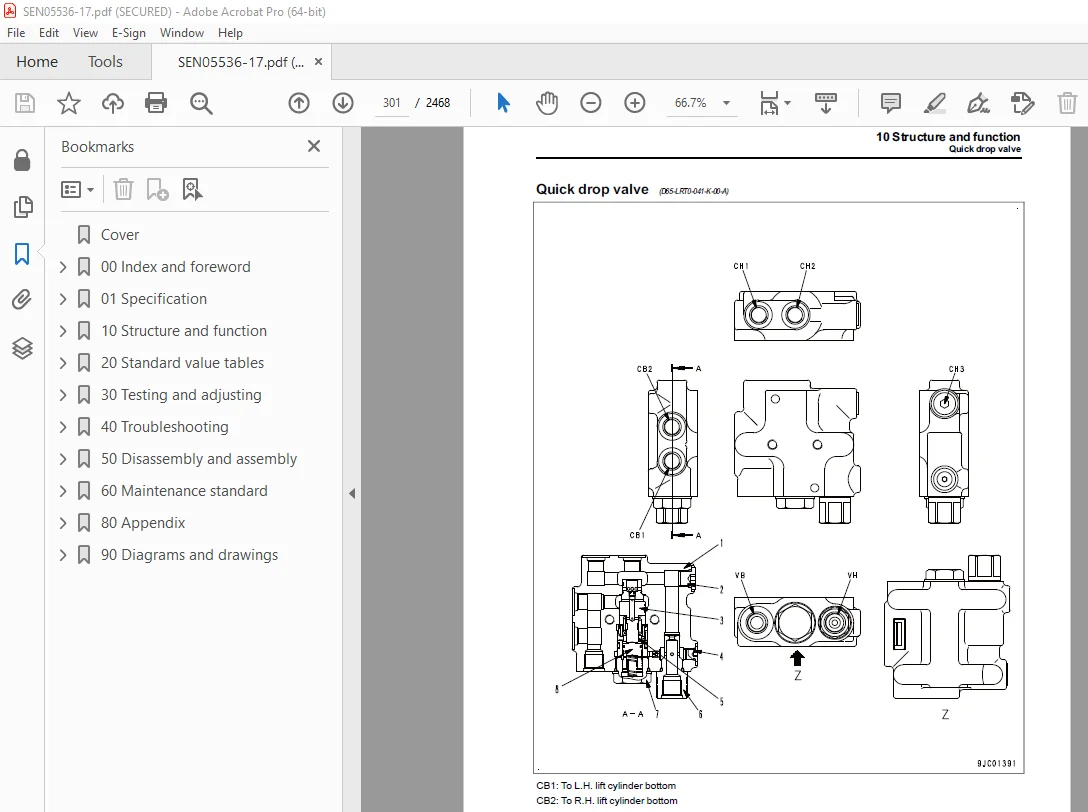
Quick drop valve 301
Work equipment lock solenoid valve 304
Pitch selector solenoid valve 309
Angle control EPC valve 310
Hydraulic oil cooler bypass valve 315
PPC accumulator 316
Work equipment 317
Work equipment 317
Ripper 320
Piston valve 321
Cab and its attachments 323
ROPS cab 323
Cab mount 325
Electrical system 326
Engine control system 326
Cooling system control system 329
Palm command control system 331
Machine monitor system 335
KOMTRAX system 355
System component parts 358
Sensor 373
20 Standard value tables 389
Table of contents 390
Standard service value table 391
Standard value table for engine 391
Standard value table for machine 393
30 Testing and adjusting 417
Table of contents 418
Related information on testing and adjusting 420
Tools for testing, adjusting, and troubleshooting 420
Engine and cooling system 424
Testing engine speed 424
Measuring boost pressure 426
Measuring exhaust gas temperature 427
Measuring exhaust gas color 429
Test mass air flow and temperature sensor 431
Measuring and adjusting valve clearance 433
Measuring compression pressure 435
Measuring blowby pressure 437
Measuring engine oil pressure 439
Measuring EGR valve and KVGT oil pressure 440
Releasing remaining pressure from fuel system 441
Measuring fuel pressure 442
Measuring fuel delivery, return rate and leakage 449
Handling cylinder cutout mode operation 453
Handling no-injection cranking operation 454
Bleeding air from fuel system 455
Testing fuel circuit for leakage 456
Testing and adjusting air conditioner compressor belt tension 457
Check alternator belt, replace 458
Check auto-tensioner, replace 460
Adjusting fuel dial and decelerator pedal 462
Writing compensation amount for soot accumulation caused by ash on engine controller 464
Power train 466
Measuring power train oil pressure 466
Adjusting transmission output shaft speed sensor (replacement procedure) 471
Simple test procedure for brake performance 472
Adjusting brake pedal 473
Adjusting parking brake lever 475
Retrieval of disabled machine using brake release device 477
Undercarriage and frame 480
Adjusting idler clearance 480
Checking sprocket wear 481
Testing and adjusting track tension 482
Hydraulic system 483
Releasing remaining pressure in work equipment cylinder 483
Measuring and adjusting work equipment and HSS oil pressure 484
Measuring source pressure of control circuit 487
Measuring PPC valve output pressure 488
Adjusting play of work equipment PPC valve 491
Isolating the parts causing hydraulic drift in blade and ripper 493
Measure internal oil leakage of work equipment cylinder 494
Checking fan speed 495
Measuring fan circuit oil pressure 496
Bleeding air from hydraulic circuit 497
Work equipment 499
Adjusting work equipment lock lever 499
Adjustment of straight tilt dozer 500
Cab and its attachments 502
Adjusting operator’s cab 502
Adjusting play of blade center ball 505
Electrical system 506
Special functions of machine monitor 506
Handling voltage circuit of engine controller 568
Adjustment method when controller has been replaced 569
Testing diodes 571
Pm clinic 572
Pm Clinic service 572
Pm Clinic check sheet 578
40 Troubleshooting 589
Table of contents 590
Related information on troubleshooting 597
Troubleshooting points 597
Sequence of events in troubleshooting 599
Check before troubleshooting 601
Inspection procedure before troubleshooting 603
Preparation for troubleshooting of electrical system 623
Classification and procedures for troubleshooting 627
Classification and procedures for troubleshooting numbers 629
Information in troubleshooting table 632
Troubleshooting method for open circuit in wiring harness of pressure sensor system 634
Connector/electrical wiring connection table 636
Layout of connector 699
Connector contact identification 706
T-branch box and T-branch adapter table 745
Fuse locations table 750
Precautions for KDPF (KCSF and KDOC) Cleaning and Replacement 753
Preparation of dummy temperature sensor (for KDOC and KDPF temperature sensors) 756
Preparation of short circuit electrical connector (for failure codes [CA1883] and [CA3135]) 757
Failure codes table 758
Troubleshooting by failure code (Display of code) 769
Failure code [1500L0] 769
Failure code [15SAL1] 770
Failure code [15SALH] 772
Failure code [15SBL1] 774
Failure code [15SBLH] 776
Failure code [15SEL1] 778
Failure code [15SELH] 780
Failure code [15SFL1] 782
Failure code [15SFLH] 784
Failure code [15SGL1] 786
Failure code [15SGLH] 788
Failure code [15SJL1] 790
Failure code [15SJLH] 792
Failure code [1800MW] 794
Failure code [879AKA] 796
Failure code [879AKB] 797
Failure code [879BKA] 798
Failure code [879BKB] 799
Failure code [879CKA] 800
Failure code [879CKB] 801
Failure code [879DKZ] 802
Failure code [879EMC] 803
Failure code [879FMC] 804
Failure code [879GKX] 805
Failure code [989L00] 806
Failure code [989M00] 807
Failure code [989N00] 808
Failure code [A1U0N3] 809
Failure code [A1U0N4] 812
Failure code [AA10NX] 815
Failure code [AB00KE] 817
Failure code [B@BAZG] 819
Failure code [B@BCNS] 820
Failure code [B@CENS] 821
Failure code [B@HANS] 822
Failure code [CA115] 823
Failure code [CA122] 824
Failure code [CA123] 827
Failure code [CA131] 830
Failure code [CA132] 833
Failure code [CA144] 836
Failure code [CA145] 839
Failure code [CA153] 842
Failure code [CA154] 845
Failure code [CA187] 848
Failure code [CA221] 851
Failure code [CA222] 855
Failure code [CA227] 858
Failure code [CA234] 859
Failure code [CA238] 861
Failure code [CA239] 863
Failure code [CA271] 865
Failure code [CA272] 868
Failure code [CA281] 871
Failure code [CA295] 872
Failure code [CA322] 873
Failure code [CA323] 876
Failure code [CA324] 879
Failure code [CA325] 882
Failure code [CA331] 885
Failure code [CA332] 888
Failure code [CA343] 891
Failure code [CA351] 892
Failure code [CA352] 893
Failure code [CA356] 895
Failure code [CA357] 898
Failure code [CA386] 902
Failure code [CA428] 903
Failure code [CA429] 905
Failure code [CA435] 908
Failure code [CA441] 910
Failure code [CA442] 913
Failure code [CA449] 914
Failure code [CA451] 918
Failure code [CA452] 921
Failure code [CA488] 924
Failure code [CA515] 925
Failure code [CA516] 927
Failure code [CA553] 930
Failure code [CA555] 931
Failure code [CA556] 932
Failure code [CA559] 934
Failure code [CA595] 939
Failure code [CA687] 940
Failure code [CA689] 943
Failure code [CA691] 949
Failure code [CA692] 952
Failure code [CA697] 955
Failure code [CA698] 956
Failure code [CA731] 957
Failure code [CA778] 960
Failure code [CA1117] 966
Failure code [CA1664] 967
Failure code [CA1691] 971
Failure code [CA1695] 975
Failure code [CA1696] 977
Failure code [CA1843] 979
Failure code [CA1844] 982
Failure code [CA1879] 985
Failure code [CA1881] 988
Failure code [CA1883] 991
Failure code [CA1921] 997
Failure code [CA1922] 1000
Failure code [CA1942] 1007
Failure code [CA1993] 1009
Failure code [CA2185] 1013
Failure code [CA2186] 1015
Failure code [CA2249] 1017
Failure code [CA2265] 1018
Failure code [CA2266] 1021
Failure code [CA2271] 1024
Failure code [CA2272] 1028
Failure code [CA2288] 1033
Failure code [CA2311] 1034
Failure code [CA2349] 1035
Failure code [CA2353] 1039
Failure code [CA2357] 1042
Failure code [CA2373] 1045
Failure code [CA2374] 1048
Failure code [CA2375] 1051
Failure code [CA2376] 1054
Failure code [CA2381] 1057
Failure code [CA2382] 1060
Failure code [CA2383] 1064
Failure code [CA2386] 1068
Failure code [CA2387] 1071
Failure code [CA2554] 1076
Failure code [CA2555] 1080
Failure code [CA2556] 1083
Failure code [CA2637] 1086
Failure code [CA2639] 1090
Failure code [CA2961] 1093
Failure code [CA2973] 1094
Failure code [CA3133] 1095
Failure code [CA3134] 1098
Failure code [CA3135] 1101
Failure code [CA3251] 1107
Failure code [CA3253] 1112
Failure code [CA3254] 1116
Failure code [CA3255] 1121
Failure code [CA3256] 1126
Failure code [CA3311] 1131
Failure code [CA3312] 1136
Failure code [CA3313] 1141
Failure code [CA3314] 1146
Failure code [CA3315] 1152
Failure code [CA3316] 1160
Failure code [CA3317] 1165
Failure code [CA3318] 1171
Failure code [CA3319] 1179
Failure code [CA3321] 1185
Failure code [CA3322] 1190
Failure code [CA3419] 1198
Failure code [CA3421] 1200
Failure code [CA3741] 1203
Failure code [D130KA] 1204
Failure code [D130KB] 1207
Failure code [D19DKA] 1210
Failure code [D19DKB] 1213
Failure code [D19JKZ] 1215
Failure code [D811MC] 1219
Failure code [D862KA] 1220
Failure code [D8ALKA] 1221
Failure code [D8ALKB] 1223
Failure code [D8AQKR] 1225
Failure code [DAF0MB] 1227
Failure code [DAF0MC] 1228
Failure code [DAF8KB] 1229
Failure code [DAF9KQ] 1231
Failure code [DAFGMC] 1232
Failure code [DAFLKA] 1233
Failure code [DAFLKB] 1235
Failure code [DAFQKR] 1237
Failure code [DAZ9KQ] 1238
Failure code [DAZQKR] 1239
Failure code [DB2QKR] 1246
Failure code [DB2RKR] 1253
Failure code [DBE0KT] 1260
Failure code [DBE1KK] 1261
Failure code [DBE2KK] 1265
Failure code [DBE5KK] 1269
Failure code [DBE6KK] 1272
Failure code [DBE7KK] 1274
Failure code [DBE9KQ] 1276
Failure code [DBELKA] 1277
Failure code [DBELKB] 1279
Failure code [DBEQKR] 1281
Failure code [DBERKR] 1283
Failure code [DD12KA] 1285
Failure code [DD12KB] 1287
Failure code [DD13KA] 1289
Failure code [DD13KB] 1291
Failure code [DD14KA] 1293
Failure code [DD14KB] 1295
Failure code [DDKFL4] 1297
Failure code [DDKGL4] 1300
Failure code [DDKHKA] 1303
Failure code [DDKHKB] 1305
Failure code [DDN7KA] 1307
Failure code [DDN7KB] 1309
Failure code [DDNLKA] 1311
Failure code [DDNLKB] 1313
Failure code [DGS1KA] 1315
Failure code [DGS1KX] 1316
Failure code [DGT1KA] 1319
Failure code [DGT1KX] 1320
Failure code [DH21KA] 1323
Failure code [DH21KB] 1326
Failure code [DHA4KA] 1329
Failure code [DHTDKA] 1331
Failure code [DHTDKB] 1334
Failure code [DK10KA] 1337
Failure code [DK10KB] 1340
Failure code [DK30KA] 1343
Failure code [DK30KB] 1347
Failure code [DK30KX] 1350
Failure code [DK30KZ] 1351
Failure code [DK30L8] 1352
Failure code [DK31KA] 1353
Failure code [DK31KB] 1357
Failure code [DK40KA] 1360
Failure code [DK40KB] 1363
Failure code [DK55KX] 1366
Failure code [DK55KZ] 1367
Failure code [DK55L8] 1368
Failure code [DK56KA] 1369
Failure code [DK56KB] 1373
Failure code [DK57KA] 1376
Failure code [DK57KB] 1380
Failure code [DKH1KA] 1383
Failure code [DKH1KB] 1386
Failure code [DLM3KA] 1389
Failure code [DLM3MB] 1391
Failure code [DLT3KA] 1392
Failure code [DLT3KB] 1395
Failure code [DR21KX] 1397
Failure code [DR31KX] 1398
Failure code [DV20KB] 1399
Failure code [DW5AKA] 1401
Failure code [DW5AKB] 1403
Failure code [DW5AKY] 1405
Failure code [DW7BKA] 1408
Failure code [DW7BKB] 1410
Failure code [DWN1KA] 1412
Failure code [DWN1KB] 1414
Failure code [DWN1KY] 1416
Failure code [DWN2KA] 1419
Failure code [DWN2KB] 1421
Failure code [DWN2KY] 1423
Failure code [DWN5KA] 1426
Failure code [DWN5KB] 1428
Failure code [DWN5KY] 1430
Failure code [DXA2KA] 1433
Failure code [DXA2KB] 1435
Failure code [DXA2KY] 1437
Failure code [DXH1KA] 1440
Failure code [DXH1KB] 1442
Failure code [DXH1KY] 1444
Failure code [DXH4KA] 1447
Failure code [DXH4KB] 1449
Failure code [DXH4KY] 1451
Failure code [DXH5KA] 1454
Failure code [DXH5KB] 1456
Failure code [DXH5KY] 1458
Failure code [DXH6KA] 1461
Failure code [DXH6KB] 1463
Failure code [DXH6KY] 1465
Failure code [DXH7KA] 1468
Failure code [DXH7KB] 1470
Failure code [DXH7KY] 1472
Failure code [DXH8KA] 1475
Failure code [DXH8KB] 1477
Failure code [DXH8KY] 1479
Failure code [DXJ4KA] 1482
Failure code [DXJ4KB] 1484
Failure code [DXJCKA] 1486
Failure code [DXJCKB] 1488
Failure code [DXJCKY] 1490
Failure code [DXJDKA] 1492
Failure code [DXJDKB] 1494
Failure code [DXJDKY] 1496
Troubleshooting of electrical system (E-mode) 1498
E-1 Engine does not start (Engine does not crank) 1498
E-2 Manual preheating does not work 1504
E-3 Automatic preheating does not work 1507
E-4 While preheating is working, preheating monitor does not light up 1509
E-5 When starting switch is turned to ON position, machine monitor displays nothing 1511
E-6 When starting switch is turned to ON position (with engine stopped), basic check monitor lights up 1514
E-7 Air cleaner clogging monitor lights up in yellow while engine is running 1515
E-8 Charge level monitor lights up in red while engine is running 1516
E-9 Engine coolant temperature monitor lights up while engine is running 1518
E-10 Engine oil pressure monitor lights up in red while engine is running 1519
E-11 Power train oil temperature monitor lights up while engine is running 1520
E-12 Hydraulic oil temperature monitor lights up while engine is running 1521
E-13 Engine coolant temperature gauge does not indicate correct temparature 1522
E-14 Fuel level gauge does not indicate correct level 1523
E-15 Power train oil temperature gauge does not indicate correct temperature 1525
E-16 Hydraulic oil temperature gauge does not indicate correct temperature 1526
E-17 Operation mode does not change 1527
E-18 Gearshift mode does not change 1528
E-19 Operating customize switch does not display customize screen 1529
E-20 Modifying setting on customize screen does not change setting of machine 1530
E-21 Reverse slow mode does not function properly 1531
E-22 Alarm buzzer does not sound or does not stop sounding 1532
E-23 While starting switch is in OFF position, service meter is not displayed 1533
E-24 Service mode cannot be selected 1534
E-25 Horn does not sound 1535
E-26 Horn does not stop sounding 1536
E-27 Backup alarm does not sound 1537
E-28 Backup alarm does not stop sounding 1539
E-29 Headlamp does not light up 1540
E-30 Rear lamp does not light up 1543
E-31 No wiper operates continuously or intermittently 1545
E-32 Front wiper does not operate (Failure in both continuous and intermittent operations) 1548
E-33 Rear wiper does not operate (Failure in both continuous and intermittent operations) 1551
E-34 Left door wiper does not operate (Failure of both continuous and intermittent operations) 1554
E-35 Right door wiper does not operate (Failure of both continuous and intermittent operations) 1557
E-36 KOMTRAX system does not operate properly 1560
Troubleshooting of hydraulic and mechanical system (H-mode) 1562
Information described in troubleshooting table (H-mode) 1562
System diagram of hydraulic and mechanical system 1563
List of Failure Mode and Cause 1565
H-1 Machine lacks power (insufficient drawbar pull) 1568
H-2 Machine cannot travel (at 2nd or 3rd speed) 1570
H-3 Machine does not start at all gear speeds 1571
H-4 Machine travels only in one direction, either forward or in reverse 1572
H-5 Large time lag at gear shifting or directional selection 1573
H-6 Machine cannot be steered (machine does not turn left or right) 1574
H-7 Steering speed or power is insufficient 1575
H-8 Brake does not operate 1576
H-9 Torque converter does not lock up 1577
H-10 Power train oil overheats 1578
H-11 Unusual noise is heard from around HSS and work equipment pump or HSS motor 1579
H-12 All work equipment operates slowly 1580
H-13 All work equipment does not operate 1581
H-14 Blade lift speed or power is low 1582
H-15 Blade tilt speed or power is low 1583
H-16 Blade angle speed or power is low 1584
H-17 Ripper lift speed or power is low 1585
H-18 Hydraulic drift of lifted blade is large 1586
H-19 Hydraulic drift of tilted blade is large 1587
H-20 Hydraulic drift of lifted ripper is large 1588
H-21 Fan speed is abnormal (high, low, or no rotation) 1589
H-22 Unusual noise is heard from around fan 1591
Troubleshooting of engine (S-mode) 1592
Information mentioned in troubleshooting table (S mode) 1592
S-1 Engine does not crank when starting switch is turned to START position 1593
S-2 The engine cranks but exhaust smoke does not come out 1594
S-3 Fuel is being injected but engine does not start (incomplete combustion: engine cranks but does not start) 1595
S-4 Startability is poor 1596
S-5 Engine does not pick up smoothly 1598
S-6 Engine stops during operation 1600
S-7 Engine runs rough or is unstable 1602
S-8 Engine lacks power 1603
S-9 KDPF gets clogged in a short time 1605
S-10 Engine oil consumption is excessive 1607
S-11 Engine oil becomes contaminated early 1608
S-12 Fuel consumption is excessive 1609
S-13 Oil is in coolant (or coolant spurts or coolant level goes down) 1610
S-14 Oil pressure drops 1611
S-15 Fuel mixes into engine oil 1612
S-16 Water mixes into engine oil (milky) 1613
S-17 Coolant temperature rises too high (overheating) 1614
S-18 Unusual noise is heard 1615
S-19 Vibration is excessive 1616
S-20 Air cannot be bled from fuel circuit 1617
S-21 Frequent active regeneration 1618
S-22 Active regeneration takes time 1619
S-23 White smoke is exhausted during active regeneration 1620
50 Disassembly and assembly 1621
Table of contents 1622
Related information on disassembly and assembly 1624
How to read this manual 1624
Coating materials list 1626
Special tool list 1630
Sketches of special tools 1641
Engine and cooling system 1656
Removal and installation of fuel supply pump assembly 1656
Removal and installation of fuel injector assembly 1666
Removal and installation of cylinder head assembly 1687
Removal and installation of radiator assembly 1718
Removal and installation of aftercooler assembly 1730
Removal and installation of hydraulic oil cooler assembly 1736
Removal and installation of power train oil cooler assembly 1741
Removal and installation of cooling fan drive assembly 1748
Removal and installation of cooling fan motor assembly 1753
Removal and installation of engine assembly 1756
Removal and installation of damper assembly 1779
Removal and installation of engine front oil seal 1785
Removal and installation of engine rear oil seal 1792
Removal and installation of engine hood assembly 1805
Removal and installation of fuel tank assembly 1810
Removal and installation of KDPF cover 1815
Removal and installation of KDPF assembly 1818
Disassembly and assembly of KDPF 1826
Removal and installation of KCCV assembly 1836
Removal and installation of air cleaner assembly 1839
Power train 1842
Removal and installation of power train unit assembly 1842
Disconnecting and connecting of power train unit assembly 1853
Disassembly and assembly of PTO 1859
Disassembly and assembly of torque converter 1865
Disassembly and assembly of TORQFLOW transmission 1878
Disassembly and assembly of HSS 1908
Removal and installation of final drive assembly 1932
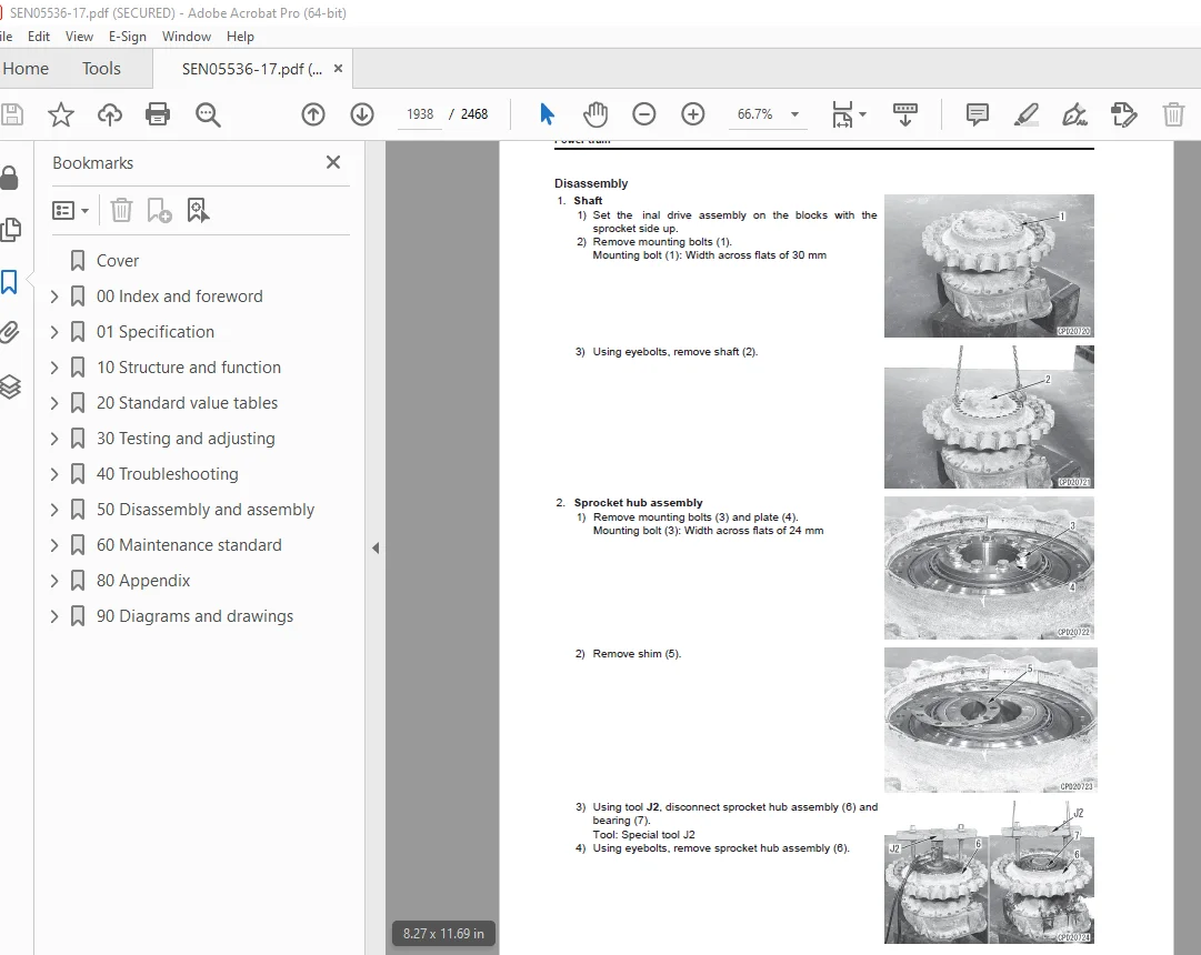
Disassembly and assembly of final drive 1937
Undercarriage and frame 1954
Removal and installation of track frame assembly 1954
Removal and installation of idler assembly 1959
Disassembly and assembly of idler 1962
Removal and installation of recoil spring assembly 1968
Disassembly and assembly of recoil spring 1971
Removal and installation of track roller assembly 1976
Disassembly and assembly of track roller 1980
Removal and installation of carrier roller assembly 1986
Disassembly and assembly of carrier roller 1989
Separation and connection of track shoe assembly (normal track shoes) 1993
Separation and connection of track shoe assembly (PLUS type track shoes) 1998
Overall disassembly and assembly of track shoe (standard type track shoe) 2000
Overall disassembly and assembly of track shoe (PLUS type track shoe) 2014
Disassembly and assembly of one link in field (standard type track shoe) 2027
Disassembly and assembly of one link in field (PLUS type track shoe) 2036
Removal and installation of pivot shaft assembly 2044
Removal and installation of equalizer bar assembly 2047
Disassembly and assembly of equalizer bar side bushing 2052
Hydraulic system 2054
Removal and installation of hydraulic tank assembly 2054
Removal and installation of control valve assembly 2062
Disassembly and assembly of control valve 2078
Disassembly and assembly of blade PPC valve 2080
Disassembly and assembly of ripper PPC valve 2082
Removal and installation of HSS pump and cooling fan pump assembly 2084
Removal and installation of steering lubrication pump and power train pump assembly 2089
Removal and installation of scavenging pump assembly 2094
Removal and installation of HSS motor assembly 2097
Disassembly and assembly of hydraulic cylinder 2102
Work equipment 2110
Removal and installation of blade assembly (ST-TPP dozer) 2110
Removal and installation of blade assembly (PAT dozer) 2116
Removal and installation of ripper assembly 2122
Cab and its attachments 2128
Removal and installation of ROPS cab assembly 2128
Removal and installation of operator’s cab glass (adhered window glass) 2145
Removal and installation of operator’s seat assembly 2152
Removal and installation of seat belt assembly 2155
Removal and installation of air conditioner unit assembly 2158
Removal and installation of air conditioner compressor assembly 2171
Electrical system 2175
Removal and installation of machine monitor assembly 2175
Removal and installation of engine controller assembly 2180
Removal and installation of power train controller assembly 2183
Removal and installation of mass air flow and temperature sensor 2186
Removal and installation of KOMTRAX terminal 2189
60 Maintenance standard 2195
Table of contents 2196
Engine and cooling system 2197
Engine mount 2197
Damper 2198
Cooling system 2200
Cooling fan pump 2201
Cooling fan motor 2204
Power train 2206
Power train mount 2206
Universal joint 2208
Torque converter and PTO 2209
Transmission 2212
Transmission control valve 2216
Forward and reverse clutch ECMV and gear shift clutch ECMV 2217
Lockup clutch ECMV 2218
Main relief valve and torque converter relief valve 2219
Transmission lubricating oil relief valve 2220
Bevel gear shaft, HSS, and brake 2221
Brake valve 2226
Final drive 2227
Sprocket 2230
Undercarriage and frame 2234
Main frame 2234
Suspension 2236
Track frame and idler cushion 2238
Idler 2240
Track roller 2242
Carrier roller 2246
Track shoe 2248
Hydraulic system 2253
Hydraulic tank 2253
Scavenging pump 2254
Steering lubricating oil pump and power train pump 2255
HSS pump 2256
HSS motor 2258
Control valve 2260
Blade PPC valve 2267
Ripper PPC valve 2269
Quick drop valve 2271
Work equipment lock solenoid valve 2273
Angle control EPC valve 2276
Work equipment 2277
Work equipment 2277
Cutting edge and end bit 2284
Ripper 2286
Lift cylinder 2287
Tilt cylinder 2288
Pitch cylinder 2289
Angle cylinder 2290
Ripper cylinder 2291
Cab and its attachments 2292
Cab mount 2292
80 Appendix 2293
Table of contents 2294
Air conditioner components 2295
Precautions for refrigerant 2295
Air conditioner component 2296
Configuration and function of refrigeration cycle 2299
Outline of refrigeration cycle 2300
Air conditioner unit 2302
Dual pressure switch 2309
Air conditioner controller 2310
Compressor 2311
Condenser 2312
Receiver drier 2313
Sunlight sensor 2314
Outside air temperature sensor 2315
Procedure for testing and troubleshooting 2316
Circuit diagram and arrangement of connector pins 2318
System diagram 2320
Input and output signals of the air conditioner controller 2321
Layout of air conditioner related parts and connectors 2323
Testing air leakage (duct) 2332
Testing with self-diagnosis function 2335
How to open the electrical system abnormality record screen in service mode of the machine monitor 2336
Testing vent (mode) changeover 2338
Testing FRESH/RECIRC air changeover 2339
Testing sunlight sensor 2340
Testing (dual) pressure switch for refrigerant 2341
Testing relays 2342
Troubleshooting chart 1 2343
Troubleshooting chart 2 2344
Information in troubleshooting table 2347
Failure code list related to air conditioner 2348
Failure code [879AKA] A/C Inner Sensor Open Circuit 2349
Failure code [879AKB] A/C Inner Sensor Short Circuit 2350
Failure code [879BKA] A/C Outer sensor Open Circuit 2351
Failure code [879BKB] A/C Outer sensor Short Circuit 2353
Failure code [879CKA] Ventilating Sensor Open Circuit 2355
Failure code [879CKB] Ventilating Sensor Short Circuit 2356
Failure code [879DKZ] Sunlight sensor Open or Short Circuit 2357
Failure code [879EMC] Ventilation Damper Abnormality 2359
Failure code [879FMC] Air Mix Damper Abnormality 2360
Failure code [879GKX] Refrigerant Abnormality 2361
A-1 Troubleshooting for power supply system (Air conditioner does not operate) 2362
A-2 Troubleshooting for compressor system (Air is not cooled) 2364
A-3 Troubleshooting for blower motor system (Air does not come out or air flow is abnormal) 2367
A-4 Troubleshooting for FRESH/RECIRC air changeover 2369
Troubleshooting with gauge pressure 2371
Connection of service tool 2374
Precautions for disconnecting and connecting air conditioner piping 2376
Handling of compressor oil 2378
90 Diagrams and drawings 2381
Table of contents 2382
Hydraulic circuit diagram 2383
Symbols in hydraulic circuit diagram 2383
Power train hydraulic circuit diagram(1/3) 2387
Hydraulic circuit diagram(1/3) 2389
Electric circuit diagram 2401
Symbols in electric circuit diagram 2401
Electrical circuit diagram (1/13) 2405
Electric circuit diagram for air conditioner unit 2431
Wiring harness diagram 2433
DESCRIPTION:
Komatsu D65EX-17 D65PX-17 D65WX-17 Bulldozer Shop Manual SEN05536-17 – PDF DOWNLOAD
SERIAL NUMBERS
D65EX- 1001 and up
D65PX- 1001 and up
D65WX-1001 and up
Composition of shop manual:
• This shop manual describes the technical information required for the services performed in a workshop.
The shop manual is divided into the following chapters for the convenience of use.
00. Index and foreword
• This section includes the index, foreword, safety and basic information.
01. Specification
• This section explains the specifications of the machine.
10. Structure and function
• This section explains the structure and function of the machine. The section of “Structure and function”
serves not only to give an understanding for the structure of each component, but also serves as
reference material for troubleshooting.
20. Standard value table
• The standard values for a new machine and trouble shooting are indicated. This standard value table is
used for testing and adjusting, and determining a failure at troubleshooting.
30. Testing and adjusting
• This section describes the measuring tools and how to measure, and how to adjust various parts. As for
the standard value and failure criterion, see the standard value table.
40. Troubleshooting
• This section describes the troubleshooting in a suspected area when a failure occurs and the remedy for
the failure. Troubleshooting is described by each failure mode.
50. Disassembly and assembly
• This section explains the procedures for removing, installing, disassembling, and assembling each part or
component and the special tools for the works as well as precautions for doing them safely. In addition,
tightening torque, and quantity and weight of coating material, oil, grease, and coolant required for the
works are also explained.
60. Maintenance standard
• This section describes the maintenance standard values for each component. This section gives the
criterion values for each component and required remedy at disassembly or maintenance.
80. Appendix
• The structure and function, testing and adjusting, and troubleshooting for all of the other components or
equipment which can not be separately classified are explained together in the appendix.
90. Diagrams and drawings
• This section gives hydraulic circuit diagrams and electrical circuit diagrams.
S.V 31/12/24


