Komatsu D65EX-16 D65PX-16 D65WX-16 Bulldozer Shop Manual SEN04887-14 PDF
$37.95
Komatsu D65EX-16 D65PX-16 D65WX-16 Bulldozer Shop Manual SEN04887-14 – PDF DOWNLOAD
SERIAL NUMBERS
D65EX- 80001 and up
D65PX- 80001 and up
D65WX-80001 and up
Description
Komatsu D65EX-16 D65PX-16 D65WX-16 Bulldozer Shop Manual SEN04887-14 – PDF DOWNLOAD
FILE DETAILS:
Komatsu D65EX-16 D65PX-16 D65WX-16 Bulldozer Shop Manual SEN04887-14 – PDF DOWNLOAD
Language : English
Pages : 1580
Downloadable : Yes
File Type : PDF
IMAGES PREVIEW OF THE MANUAL:
TABLE OF CONTENTS:
Komatsu D65EX-16 D65PX-16 D65WX-16 Bulldozer Shop Manual SEN04887-14 – PDF DOWNLOAD
Cover 1
00 Index and foreword 0
100 Index 3
Composition of shop manual 4
Table of contents 6
200 Foreword and general information 17
Safety notice 18
How to read the shop manual 23
Explanation of terms for maintenance standard 25
Handling of electric equipment and hydraulic component 27
Handling of connectors newly used for engines 36
How to read electric wire code 39
Precautions when carrying out operation 42
Method of disassembling and connecting push-pull type coupler 45
Standard tightening torque table 48
Conversion table 52
01 General 0
100 Specification and technical data 59
Specification dimension drawing 60
Specifications 66
Weight table 78
Table of fuel, coolant and lubricants 82
10 Structure, function and maintenance standard 0
100 Engine and cooling system 85
Engine mount 87
Cooling system 88
Cooling fan pump 90
Cooling fan motor 104
Coolant preheater (subextremely cold weather spec ) 110
201 Power train, Part 1 115
Power train 116
HSS system 118
Overall view of power train unit 120
Power train hydraulic piping diagram 124
Transmission, steering and brake control 126
Damper 128
Universal joint 130
Torque converter and PTO 131
Transmission 138
Transmission control valve 156
ECMV 160
Main relief and torque converter relief valve 168
Main relief and torque converter relief valve (subextremely cold weather spec ) 170
Transmission lubrication relief valve 172
202 Power train, Part 2 175
Bevel gear shaft, HSS and brake 176
Brake valve 198
Final drive 204
Final drive (Planetary gear installed inside of sprocket type) 210
300 Undercarriage and frame 217
Main frame 218
Suspension 220
Track frame and idler cushion 230
Idler 234
Idler (Without idler support automatic thrust adjustment) 236
Track roller 236
Carrier roller 242
Sprocket 244
Track shoe 248
401 Hydraulic system, Part 1 255
Work equipment hydraulic system layout drawing 256
Work equipment control 260
Hydraulic tank and filter 262
Scavenging pump 264
Power train and steering lubrication pump 265
HSS pump 266
HSS motor 285
402 Hydraulic system, Part 2 295
Control valve 296
CLSS 305
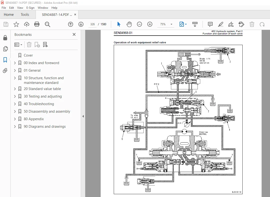
Function and operation of each valve 308
403 Hydraulic system, Part 3 333
PPC valve (blade lift, blade tilt) 334
PPC valve (ripper) 340
Electric lever (steering) 344
Quick drop valve 348
Work equipment lock solenoid valve 350
Pitch selector solenoid valve 354
Hydraulic oil cooler bypass valve 355
Accumulator 356
500 Work equipment 359
Blade 360
Cutting edge and end bit 368
Ripper (Multi shank) 370
Ripper (Single shank) 371
Hydraulic cylinder 372
Piston valve 376
600 Cab and its attachme 379
Cab mount 380
Cab 381
Subextremely cold spec cab (subextremely cold weather spec ) 382
600 Cab and its attachmentsFRP canopy mountFRP canopy mount 383
FRP canopy 384
700 Electrical system 387
Monitor system 388
Engine control system 404
Cooling system control system 407
Electronic steering control system 409
KOMTRAX system 412
KOMTRAX terminal (for GPRS) 414
System components 415
Sensor 423
20 Standard value table 0
100 Standard service value table 431
Standard service value table for engine 432
Standard service value table for chassis 434
30 Testing and adjusting 0
101 Testing and adjusting, Part 1 447
Tools for testing, adjusting, and troubleshooting 448
Testing engine speed 451
Testing intake air pressure (boost pressure) 453
Testing exhaust temperature 455
Testing exhaust gas color 457
Adjusting valve clearance 458
Testing compression pressure 460
Testing blow-by pressure 464
Testing engine oil pressure 465
Handling of fuel system devices 466
Releasing residual pressure from fuel system 466
Testing fuel pressure 467
Testing fuel return and leak amount 472
Bleeding air from fuel circuit 474
Testing fuel circuit for leakage 475
Handling of reduced cylinder mode operation 476
Handling of no injection cranking operation 476
Testing and adjusting air conditioner compressor belt tension 477
Replacing alternator belt 478
Adjusting fuel control dial and decelerator pedal 479
Handling controller high-voltage circuit 480
102 Testing and adjusting, Part 2 483
Testing power train oil pressure 485
Adjusting transmission output shaft speed sensor (replacement procedure) 490
Simple test procedure for brake performance 491
Adjusting brake pedal 492
Adjusting parking brake lever 494
Emergency escape method when power train has trouble 496
Adjusting clearance of idler 499
Inspecting wear of sprocket 500
Inspecting wear of sprocket 501
Testing and adjusting track shoe tension 502
Testing and adjusting work equipment and HSS oil pressure 503
Testing control circuit basic pressure 506
Testing PPC valve output pressure 507
Adjusting work equipment PPC valve play 509
Testing internal leakage of work equipment cylinder 513
Bleeding air from work equipment cylinder 514
Releasing residual pressure from work equipment cylinder 514
Checking parts which caused hydraulic drift of blade or ripper 515
Adjusting work equipment lock lever 516
Adjusting work equipment lock lever (FRP canopy specification) 517
Testing fan speed 519
Testing fan circuit oil pressure 520
Bleeding air from fan pump 521
Bleeding air from HSS pump 522
Adjusting straight tiltdozer 523
Adjusting play of blade center ball1 525
Adjusting operator’s cab 526
103 Testing and adjusting, Part 3 531
Special functions of machine monitor (EMMS) 532
104 Testing and adjusting, Part 4 589
Handling of voltage circuit of engine controller 590
Adjustment method when controller has been replaced 591
Preparation work for troubleshooting of electrical 593
Inspection procedure of diode 597
Pm-Clinic service 598
40 Troubleshooting 0
100 Failure code table and fuse locations 613
Failure codes table 614
Fuse locations 619
200 General information on troubleshooting 623
Points to remember when troubleshooting 624
How to proceed troubleshooting 625
Checks before troubleshooting 626
Classification and procedures for troubleshooting 628
Symptom supposed to be failure and troubleshooting No 632
Information contained in troubleshooting table 634
Troubleshooting method for disconnecting wiring harness of pressure sensor system 636
Connector list and stereogram 638
Connection table for connector pin numbers 652
T- branch box and T- branch adapter table 688
301 Troubleshooting by failure code (Display of code), Part 1 693
Failure code [1500L0] Transmission clutch: Abnormal 695
Failure code [15SAL1] Forward clutch: Fill high 696
Failure code [15SALH] Forward clutch: Fill low 698
Failure code [15SBL1] Reverse clutch: Fill high 700
Failure code [15SBLH] Reverse clutch: Fill low 702
Failure code [15SEL1] Speed 1st clutch: Fill high 704
Failure code [15SELH] Speed 1st clutch: Fill low 706
Failure code [15SFL1] Speed 2nd clutch: Fill high 708
Failure code [15SFLH] Speed 2nd clutch: Fill low 710
Failure code [15SGL1] Speed 3rd clutch: Fill high 712
Failure code [15SGLH] Speed 3rd clutch: Fill low 714
Failure code [15SJL1] L/U: Fill high 716
Failure code [15SJLH] L/U: Fill low 718
Failure code [AB00MA] Battery Charge Abnormal 720
Failure code [B@BAZG] Eng Oil Press Low 722
Failure code [B@BCNS] Eng Water Overheat 722
Failure code [B@CENS] T/C Oil Overheat 723
Failure code [B@HANS] Hyd Oil Overheat 723
302 Troubleshooting by failure code (Display of code), Part 2 725
Failure code [CA111] ECM Critical Internal Failure 727
Failure code [CA115] Eng Ne and Bkup Speed Sens Error 727
Failure code [CA122] Chg Air Press Sensor High Error 728
Failure code [CA123] Chg Air Press Sensor Low Error 730
Failure code [CA131] Throttle Sensor High Error 732
Failure code [CA132] Throttle Sensor Low Error 734
Failure code [CA144] Coolant Temp Sens High Error 736
Failure code [CA145] Coolant Temp Sens Low Error 738
Failure code [CA153] Chg Air Temp Sensor High Error 740
Failure code [CA154] Chg Air Temp Sensor Low Error 742
Failure code [CA155] Chg Air Temp High Speed Derate 744
Failure code [CA187] Sens Supply 2 Volt Low Error 746
Failure code [CA221] Ambient Press Sens High Error 748
Failure code [CA222] Ambient Press Sens Low Error 750
Failure code [CA227] Sens Supply 2 Volt High Error 752
Failure code [CA234] Eng Overspeed 752
Failure code [CA238] Ne Speed Sens Supply Volt Error 753
Failure code [CA271] IMV/PCV1 Short Error 754
Failure code [CA272] IMV/PCV1 Open Error 756
Failure code [CA281] Abnormal supply pump pressure balance 758
Failure code [CA322] Inj #1(L#1) Open/Short Error 760
Failure code [CA323] Inj #5(L#5) Open/Short Error 762
Failure code [CA324] Inj #3(L#3) Open/Short Error 764
Failure code [CA325] Inj #6(L#6) Open/Short Error 766
Failure code [CA331] Inj #2(L#2) Open/Short Error 768
Failure code [CA332] Inj #4(L#4) Open/Short Error 770
303 Troubleshooting by failure code (Display of code), Part 3 773
Failure code [CA342] Calibration Code Incompatibility 775
Failure code [CA351] Injectors Drive Circuit Error 775
Failure code [CA352] Sens Supply 1 Volt Low Error 776
Failure code [CA386] Sens Supply 1 Volt High Error 778
Failure code [CA428] Water in Fuel Sensor High Error 780
Failure code [CA429] Water in Fuel Sensor Low Error 782
Failure code [CA435] Eng Oil Press Sw Error 784
Failure code [CA441] Battery Voltage Low Error 786
Failure code [CA442] Battery Voltage High Error 788
Failure code [CA449] Rail Press Very High Error 790
Failure code [CA451] Rail Press Sensor High Error 792
Failure code [CA452] Rail Press Sensor Low Error 794
Failure code [CA488] Chg Air Temp High Torque Derate 796
Failure code [CA553] Rail Press High Error 797
Failure code [CA559] Rail Press Low Error 798
Failure code [CA689] Eng Ne Speed Sensor Error 800
Failure code [CA731] Eng Bkup Speed Sens Phase Error 804
Failure code [CA757] All Continuous Data Lost Error 805
Failure code [CA778] Eng Bkup Speed Sensor Error 806
Failure code [CA1633] KOMNET Datalink Timeout Error 809
Failure code [CA2185] Throt Sens Sup Volt High Error 810
Failure code [CA2186] Throt Sens Sup Volt Low Error 812
Failure code [CA2249] Rail Press Very Low Error 814
Failure code [CA2265] Fuel Feed Pump Open Error 816
Failure code [CA2266] Fuel Feed Pump Short Error 818
Failure code [CA2311] IMV Solenoid Error 819
Failure code [CA2555] Grid Htr Relay Volt High Error 820
Failure code [CA2556] Grid Htr Relay Volt Low Error 822
304 Troubleshooting by failure code (Display of code), Part 4 825
Failure code [D110KB] Battery relay drive: Short circuit 828
Failure code [D130KA] Neutral relay: Disconnection 830
Failure code [D130KB] Neutral relay: Short circuit 832
Failure code [D161KA] Back-up alarm relay: Disconnection 834
Failure code [D161KB] Back-up alarm relay: Short circuit 836
Failure code [D862KA] GPS Antenna Open Circuit 838
Failure code [DAFRKR] CAN Disconnection 839
Failure code [DAFRMC] CAN Discon (Monitor Detected) 840
Failure code [DB2RKR] CAN Disconnection 843
Failure code [DBE0KT] PT controller: Abnormality in controller 848
Failure code [DBE1KK] Battery direct Source voltage reduction 850
Failure code [DBE2KK] Solenoid Source voltage reduction 852
Failure code [DBE5KK] PT cont : Sensor voltage 5V (1) reduction 854
Failure code [DBE6KK] PT cont : Sensor voltage 24V reduction 856
Failure code [DBE7KK] PT cont : Sensor voltage 5V (2) reduction 858
Failure code [DBE9KQ] PT controller: Type select signal 860
Failure code [DD12KA] Shift up Sw: Disconnection 862
Failure code [DD12KB] Shift up Sw: Short circuit 864
Failure code [DD13KA] Shift down Sw: Disconnection 866
Failure code [DD13KB] Shift down Sw: Short circuit 868
Failure code [DD14KA] Parking lever Sw: Disconnection 870
Failure code [DD14KB] Parking lever Sw: Short circuit 872
305 Troubleshooting by failure code (Display of code), Part 5 875
Failure code [DDN7KA] WEQ Knob Sw (down): Disconnection 878
Failure code [DDN7KB] WEQ Knob Sw (down): Short circuit 880
Failure code [DDN8KA] WEQ Knob Sw (up): Disconnection 882
Failure code [DDN8KB] WEQ Knob Sw (up): Short circuit 884
Failure code [DDNLKA] Weq lock Sw: Disconnection 886
Failure code [DDNLKB] Weq lock Sw: Short circuit 888
Failure code [DGS1KX] Hyd oil temp sensor: Abnormal 890
Failure code [DGT1KA] T/C oil temp sensor: Disconnection 892
Failure code [DGT1KX] T/C oil temp sensor: Short circuit 894
Failure code [DH21KA] Weq pressure sensor: Disconnection 896
Failure code [DH21KB] Weq pressure sensor: Short circuit 898
Failure code [DHT5KA] T/C pressure sensor: Disconnection 900
Failure code [DHT5KB] T/C pressure sensor: Short circuit 902
Failure code [DK10KA] Fuel control Dial: Disconnection 904
Failure code [DK10KB] Fuel control Dial: Short circuit 906
Failure code [DK30KA] ST lever 1: Disconnection 908
Failure code [DK30KB] ST lever 1: Short circuit 910
Failure code [DK30KX] ST lever: Out of normal range 912
Failure code [DK30KZ] ST lever: Disconnection or short circuit 912
Failure code [DK30L8] ST lever: Signal mismatch 913
Failure code [DK31KA] ST lever 2: Disconnection 914
Failure code [DK31KB] ST lever 2: Short circuit 916
Failure code [DK40KA] Brake potentiometer: Disconnection 918
Failure code [DK40KB] Brake potentiometer: Short circuit 920
Failure code [DK55KX] FR lever: Out of normal range 922
Failure code [DK55KZ] FR lever: Disconnection or short circuit 922
Failure code [DK55L8] FR lever: Signal mismatch 923
Failure code [DK56KA] FR lever 1: Disconnection 924
Failure code [DK56KB] FR lever 1: Short circuit 926
Failure code [DK57KA] FR lever 2: Disconnection 928
Failure code [DK57KB] FR lever 2: Short circuit 930
306 Troubleshooting by failure code (Display of code), Part 6 933
Failure code [DKH1KA] Pitch angle sensor: Disconnection 936
Failure code [DKH1KB] Pitch angle sensor: Short circuit 938
Failure code [DLT3KA] T/M out-speed sensor: Disconnection 940
Failure code [DLT3KB] T/M out-speed sensor: Abnormal 941
Failure code [DW5AKA] Pitch selector Sol : Disconnection 942
Failure code [DW5AKB] Pitch selector Sol : Short circuit 943
Failure code [DW5AKY] Pitch selector Sol : Short circuit 944
Failure code [DW7BKA] Fan rev EPC: Disconnection 946
Failure code [DW7BKB] Fan rev EPC: Short circuit 947
Failure code [DWN1KA] Hss EPC1: Disconnection 948
Failure code [DWN1KB] Hss EPC1: Short circuit 949
Failure code [DWN1KY] Hss EPC1: Short circuit 950
Failure code [DWN2KA] Hss EPC2: Disconnection 951
Failure code [DWN2KB] Hss EPC2: Short circuit 952
Failure code [DWN2KY] Hss EPC2: Short circuit 953
Failure code [DWN5KA] Fan pump solenoid: Disconnection 954
Failure code [DWN5KB] Fan pump solenoid: Short circuit 955
Failure code [DWN5KY] Fan control solenoid: Short circuit 956
Failure code [DXA0KA] TVC Sol : Disconnection 958
Failure code [DXA0KB] TVC Sol : Short circuit 959
Failure code [DXA0KY] TVC Sol : Short circuit 960
Failure code [DXH1KA] Lock-up ECMV: Disconnection 961
Failure code [DXH1KB] Lock-up ECMV: Short circuit 962
Failure code [DXH1KY] Lock-up ECMV: Short circuit 964
Failure code [DXH4KA] 1st clutch ECMV: Disconnection 966
Failure code [DXH4KB] 1st clutch ECMV: Short circuit 967
Failure code [DXH4KY] 1st clutch ECMV: Short circuit 968
Failure code [DXH5KA] 2nd clutch ECMV: Disconnection 969
Failure code [DXH5KB] 2nd clutch ECMV: Short circuit 970
Failure code [DXH5KY] 2nd clutch ECMV: Short circuit 971
Failure code [DXH6KA] 3rd clutch ECMV: Disconnection 972
Failure code [DXH6KB] 3rd clutch ECMV: Short circuit 973
Failure code [DXH6KY] 3rd clutch ECMV: Short circuit 974
Failure code [DXH7KA] R clutch ECMV: Disconnection 975
Failure code [DXH7KB] R clutch ECMV: Short circuit 976
Failure code [DXH7KY] R clutch ECMV: Short circuit 978
Failure code [DXH8KA] F clutch ECMV: Disconnection 980
Failure code [DXH8KB] F clutch ECMV: Short circuit 981
Failure code [DXH8KY] F clutch ECMV: Short circuit 982
Failure code [DXJ4KA] Weq lock Sol : Disconnection 984
Failure code [DXJ4KB] Weq lock Sol : Short circuit 985
400 Troubleshooting of electrical system (E-mode) 987
Before troubleshooting of electrical system 989
Information in troubleshooting table 991
E-1 Engine does not start (starting motor does not turn) 993
E-2 Preheater does not operate 996
E-3 When starting switch is turned ON, machine monitor displays nothing 1002
E-4 When starting switch is turned ON (before starting engine), basic check item lights up 1004
E-5 Precaution item lights up while engine is running 1006
E-6 Emergency stop item lights up while engine is running 1008
E-7 Engine coolant temperature gauge does not indicate normally 1010
E-8 Fuel gauge does not indicate properly 1012
E-9 Power train oil temperature gauge (multi-gauge) does not indicate normally 1015
E-10 Hydraulic temperature gauge (multi-gauge) does not indicate normally 1016
E-11 Contents of display by machine monitor are different from applicable machine 1017
E-12 Machine monitor does not display some items 1017
E-13 Function switch does not work 1017
E-14 Operation mode does not change 1018
E-15 Gearshift mode does not change 1018
E-16 Customize function does not operate normally 1019
E-17 Customize memory function does not operate normally 1019
E-18 Alarm buzzer does not sound or does not stop 1020
E-19 When starting switch is turned OFF, service meter is not displayed 1020
E-20 Machine monitor cannot be set in service mode 1020
E-21 Horn does not sound or does not stop 1021
E-22 Back-up alarm does not sound or does not stop 1022
E-23 Head lamp or rear lamp does not light up 1024
E-24 Windshield wiper does not operate 1028
E-25 Window washer does not operate 1042
E-26 KOMTRAX system does not operate correctly 1047
500 Troubleshooting of hydraulic and mechanical system (H-mode) 1049
Failure mode and cause table 1050
Contents of troubleshooting table 1052
H-1 There is no travel power (no drawbar pull) 1053
H-2 Machine does not move (at 2nd or 3rd speed) 1054
H-3 Machine does not move at any gear speed 1055
H-4 Machine travels only in one direction, forward or in reverse 1056
H-5 When gear is shifted or travel direction is changed, large time lag is made 1057
H-6 Machine cannot be steered (Machine does not turn leftward or rightward) 1058
H-7 Steering speed or power is low 1058
H- 8 Brake does not work 1059
H-9 Overheat of power train oil 1060
H-10 Abnormal sound comes out from around HSS and work equipment pump or HSS motor 1061
H-11 All work equipment speeds are slow 1061
H-12 Work equipment does not move 1062
H-13 Blade lift speed is slow or lacks power 1062
H-14 Blade tilt speed is slow or lacks power 1063
H-15 Ripper lift speed is slow or lacks power 1063
H-16 Excessive hydraulic drift of blade lift 1064
H-17 Excessive hydraulic drift of blade tilt 1064
H-18 Excessive hydraulic drift of ripper lift 1065
600 Troubleshooting of engine (S-mode) 1067
Method of using troubleshooting charts 1069
S-1 Starting performance is poor 1072
S-2 Engine does not start 1073
S-3 Engine does not pick up smoothly 1076
S-4 Engine stops during operations 1077
S-5 Engine does not rotate smoothly 1078
S-6 Engine lacks output (or lacks power) 1079
S-7 Exhaust smoke is black (incomplete combustion) 1080
S-8 Oil consumption is excessive (or exhaust smoke is blue) 1081
S-9 Oil becomes contaminated quickly 1082
S-10 Fuel consumption is excessive 1083
S-11 Oil is in coolant (or coolant spurts back, or coolant level goes down) 1084
S-12 Oil pressure drops 1085
S-13 Oil level rises (water, fuel in oil) 1086
S-14 Coolant temperature becomes too high (overheating) 1087
S-15 Abnormal noise is made 1088
S-16 Vibration is excessive 1089
50 Disassembly and assembly 0
100 General information on disassembly and assembly 1091
How to read this manual 1092
Coating materials list 1094
Special tool list 1097
Sketches of special tools 1107
200 Engine and cooling system 1123
Removal and installation of fuel supply pump assembly 1124
Removal and installation of fuel injector assembly 1129
Removal and installation of cylinder head assembly 1139
Removal and installation of radiator assembly 1154
Removal and installation of aftercooler assembly 1157
Removal and installation of hydraulic oil cooler assembly 1159
Removal and installation of power train oil cooler assembly 1161
Removal and installation of cooling fan drive assembly 1164
Removal and installation of cooling fan motor assembly 1166
Removal and installation of main body of coolant preheater (subextremely cold weather spec) 1168
Removal and installation of coolant preheater fuel tank (Subextremely cold weather spec ) 1172
Removal and installation of coolant preheater exhaust duct (Subextremely cold weather spec ) 1174
Removal and installation of oil pan cover of coolant preheater (subextremely cold weather spec ) 1178
Removal and installation of damper assembly 1187
Removal and installation of engine front oil seal 1190
Removal and installation of engine rear oil seal 1194
Removal and installation of engine hood assembly 1202
Removal and installation of fuel tank assembly 1204
300 Power train 1207
Removal and installation of power train unit assembly 1208
Separation and connection of power train unit assembly 1212
Disassembly and assembly of PTO assembly 1217
Disassembly and assembly of torque converter assembly 1222
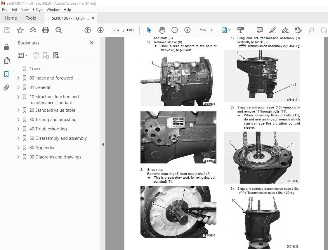
Disassembly and assembly of transmission assembly 1233
Disassembly and assembly of HSS assembly 1260
Removal and installation of final drive assembly 1280
Removal and installation of final drive assembly (Planetary gear installed inside of sprocket type) 1282
Disassembly and assembly of final drive assembly 1284
Disassembly and assembly of final drive assembly (Planetary gear installed inside of sprocket type) 1292
400 Undercarriage and frame 1307
Removal and installation of track frame assembly 1308
Removal and installation of idler assembly 1310
Removal and installation of idler assembly (Without idler support automatic thrust adjustment) 1312
Disassembly and assembly of idler assembly 1314
Disassembly and assembly of idler assembly (Without idler support automatic thrust adjustment) 1318
Removal and installation of recoil spring assembly 1323
Disassembly and assembly of recoil spring assembly 1324
Removal and installation of track roller assembly 1328
Disassembly and assembly of track roller assembly 1329
Removal and installation of carrier roller assembly 1333
Disassembly and assembly of carrier roller assembly 1334
Expansion and installation of track shoe assembly (Conventional type track shoe) 1337
Expansion and installation of track shoe assembly (PLUS type track shoe) 1340
Whole disassembly and whole assembly of track shoe assembly (Conventional type track shoe) 1341
Whole disassembly and whole assembly of track shoe assembly (PLUS type track shoe) 1355
Field disassembly and assembly of one link (Conventional type track shoe) 1367
Field disassembly and assembly of one link (PLUS type track shoe) 1374
Removal and installation of pivot shaft assembly 1379
Removal and installation of equalizer bar assembly 1380
Disassembly and assembly of equalizer bar side bushing 1382
500 Hydraulic system 1385
Removal and installation of hydraulic tank assembly 1386
Removal and installation of control valve assembly 1389
Disassembly and assembly of control valve assembly 1392
Disassembly and assembly of blade lift and tilt PPC valve assembly 1394
Disassembly and assembly of ripper PPC valve assembly 1395
Removal and installation of HSS and cooling fan pump assembly 1396
Removal and installation of power train and lubrication pump assembly 1398
Removal and installation of scavenging pump assembly 1400
Removal and installation of HSS motor assembly 1401
Disassembly and assembly of hydraulic cylinder assembly 1404
600 Work equipment 1411
Removal and installation of blade assembly (ST-TPP dozer) 1412
Removal and installation of blade assembly (PAT dozer) 1415
Removal and installation of ripper assembly 1418
700 Cab and its attachments 1423
Removal and installation of ROPS cab assembly 1424
Removal and installation of operator’s cab glass (Stuck glass) 1431
Removal and installation of floor frame assembly (FRP canopy specification) 1432
Removal and installation of operator’s cab glass (Stuck glass) 1436
Removal and installation of air conditioner unit assembly 1442
Removal and installation of air conditioner compressor assembly 1446
800 Electrical system 1449
Removal and installation of monitor panel assembly 1450
Removal and installation of engine controller assembly 1452
Removal and installation of power train controller assembly 1454
Removal and installation of KOMTRAX terminal assembly 1456
80 Appendix 0
100 Air conditioner 1459
Structure and function 1462
Air conditioner component 1462
Configuration and function of refrigerating cycle 1464
Outline of refrigerating cycle 1465
Air conditioner unit 1468
Control plate 1472
Compressor 1473
Condenser 1474
Receiver drier 1475
Testing, adjusting and troubleshooting 1476
Caution about refrigerant 1476
Troubleshooting procedure 1477
Block diagram 1478
Circuit diagram and arrangement of connector pins 1480
Detail of air conditioner unit 1482
Parts and connectors arrangement 1484
Testing air leakage (duct) 1490
Testing with self-diagnosis function 1492
Testing temperature control 1495
Testing vent (mode) changeover 1497
Testing Recirc/Fresh changeover 1500
Testing inner sensor 1501
Testing evaporator temperature sensor 1502
Testing sunlight sensor 1505
Testing (dual) pressure switch for refrigerant 1506
Testing relays and diodes 1508
Troubleshooting chart 1 1510
Troubleshooting chart 2 1511
Troubleshooting for electrical system (E mode) 1514
E-1 Power supply system (Air conditioner does not operate) 1515
E-2 Compressor and refrigerant system (Air is not cooled) 1518
E-3 Blower motor system (No air comes out or air flow is abnormal) 1521
E-4 Temperature cannot be controlled 1524
E-5 Vent (mode) cannot be changed over 1526
E-6 Recirc/Fresh air cannot be changed over 1528
Troubleshooting with gauge pressure 1530
Connection of service tool 1533
Precautions for connecting air conditioner piping 1534
Handling of compressor oil 1535
1 Control of compressor oil (Denso: ND-OIL8: For R134a) 1535
2 Adding of compressor oil 1535
3 Compressor replacement 1536
4 Applying compressor oil for O-ring 1536
90 Diagrams and drawings 0
100 Hydraulic diagrams and drawings 1539
Power train hydraulic circuit diagram 1541
Work equipment hydraulic circuit diagram 1543
200 Electrical diagrams and drawings 1549
Electrical circuit diagram 1551
Electrical circuit diagram (Sand terrain specification) 1570
Electrical circuit diagram (FRP canopy specification) 1573
DESCRIPTION:
Komatsu D65EX-16 D65PX-16 D65WX-16 Bulldozer Shop Manual SEN04887-14 – PDF DOWNLOAD
SERIAL NUMBERS
D65EX- 80001 and up
D65PX- 80001 and up
D65WX-80001 and up
How to read the shop manual
1. Composition of shop manual
This shop manual contains the necessary technical information for services performed in a workshop.
For ease of understanding, the manual is divided into the following sections.
00. Index and foreword
This section explains the shop manuals list, table of contents, safety, and basic information.
01. Specification
This section explains the specifications of the machine.
10. Structure, function and maintenance standard
This section explains the structure, function, and maintenance standard values of each component.
The structure and function sub-section explains the structure and function of each component. It
serves not only to give an understanding of the structure, but also serves as reference material for
troubleshooting. The maintenance standard sub-section explains the criteria and remedies for disassembly
and service.
20. Standard value table
This section explains the standard values for new machine and judgement criteria for testing,
adjusting, and troubleshooting. This standard value table is used to check the standard values in
testing and adjusting and to judge parts in troubleshooting.
30. Testing and adjusting
This section explains measuring instruments and measuring methods for testing and adjusting, and
method of adjusting each part. The standard values and judgement criteria for testing and adjusting
are explained in Testing and adjusting.
40. Troubleshooting
This section explains how to find out failed parts and how to repair them. The troubleshooting is
divided by failure modes. The “S mode” of the troubleshooting related to the engine may be also
explained in the Chassis volume and Engine volume. In this case, see the Chassis volume.
50. Disassembly and assembly
This section explains the special tools and procedures for removing, installing, disassembling, and
assembling each component, as well as precautions for them. In addition, tightening torque and
quantity and weight of coating material, oil, grease, and coolant necessary for the work are also
explained.
80. Appendix
This section explains the equipments which cannot be included in the other sections. This section
explains the structure, function, testing, adjusting, and troubleshooting of the equipments.
90. Diagrams and drawings (chassis volume)/Repair and replacement of parts (engine volume)
q Chassis volume
This section gives hydraulic circuit diagrams and electrical circuit diagrams.
q Engine volume
This section explains the method of reproducing, repairing, and replacing parts.
S.V 29/12/24


