Komatsu D275A-5R Bulldozer Shop Manual SEN02158-21 PDF
$39.95
Komatsu D275A-5R Bulldozer Shop Manual SEN02158-21 – PDF DOWNLOAD
SERIAL NUMBERS 35001 and up
Description
Komatsu D275A-5R Bulldozer Shop Manual SEN02158-21 – PDF DOWNLOAD
FILE DETAILS:
Komatsu D275A-5R Bulldozer Shop Manual SEN02158-21 – PDF DOWNLOAD
Language : English
Pages : 1558
Downloadable : Yes
File Type : PDF
IMAGES PREVIEW OF THE MANUAL:
TABLE OF CONTENTS:
Komatsu D275A-5R Bulldozer Shop Manual SEN02158-21 – PDF DOWNLOAD
SERIAL NUMBERS 35001 and up
COVER 1
00 Index and foreword 3
Index 3
Composition of shop manual 4
Table of contents 6
Foreword and general information 19
Safety notice 20
How to read the shop manual 25
Explanation of terms for maintenance standard 27
Handling of electric equipment and hydraulic component 29
Handling of connectors newly used for engines 38
How to read electric wire code 41
Precautions when carrying out operation 44
Method of disassembling and connecting push-pull type coupler 47
Standard tightening torque table 50
Conversion table 54
01 Specification 61
Specification and technical data 61
Specefication dimension drawings 62
Specifications 64
Weight table 76
Table of fuel, coolant and lubricants 80
10 Structure, function and maintenance standard 83
Engine and cooling system 83
Engine mount 84
Cooling system 86
Cooling fan pump 88
Cooling fan motor 96
Power train system, Part 1 103
Power train 104
Overall drawing of power train unit 106
Power train hydraulic piping drawing 110
Damper, universal joint 112
Torque converter, PTO 114
Scavenging pump 132
Transmission control 133
Transmission 135
Tranmission ECMV 149
Main relief valve and torque convertor relif valve 154
Power train pump, steering lubrication pump 157
Lubrication relief valve 158
Power train system, Part 2 161
Steering, brake control 162
Bevel gear shaft, steering clutch and brake 164
Steering control valve 174
Steering clutch ECMV 176
Steering brake ECMV 177
Parking brake valve 184
Sudden brake prevention valve 185
Final drive 186
Sprocket 192
Undercarriage and frame 195
Track frame 196
ldler cushiion 200
Idler 204
Track roller 206
Track roller bogie 208
Carrier roller 210
Track shoe 212
Main frame 214
Suspension 216
Hydraulic system, Part 1 225
Work equipment hydraulic piping diagram 226
PPC control piping diagram 230
Work equipment control 232
Hydraulic tank 234
Work equipment pump 238
Hydraulic system, Part 2 255
Control valve 256
Operation of control valve 266
Self pressure reducing valve 283
Hydraulic system, Part 3 291
PPC valve 292
PCCS lever 304
PPC lock valve 307
Hydraulic cylinder 308
Piston valve 314
Quick drop valve 315
Pin puller switch 316
Pin puller solenoid valve 317
Blade control knob 320
Pitch, dual tilt solenoid valve 321
Accumulator 322
Work equipment 325
Cylinder stay 326
Blade 328
Ripper 334
Cab and its attachments 339
Cab mount 340
Cab 341
Air conditioner 343
Electrical system 345
Engine control system 346
CRI engine control system 356
Monitor system 358
Machine monitor 360
Mode selection system 376
Electrical equipment 380
Palm command control system 382
Sensors 384
KOMTRAX system 388
20 Standard value table 391
Standard service value table 391
Standard value table for engine 392
Standard value table for machine 393
30 Testing and adjusting 401
Testing and adjusting, Part 1 401
Tools for testing, adjusting, and troubleshooting 403
Testing engine speed 407
Testing intake air pressure (Boost pressure) 410
Testing exhaust temperature 412
Testing exhaust gas color 414
Adjusting valve clearance 416
Testing compression pressure 418
Testing blow-by pressure 420
Testing engine oil pressure 421
Handling of fuel system devices 422
Releasing residual pressure from fuel system 422
Testing fuel pressure 423
Testing fuel return rate and fuel leakage 424
Bleeding air from fuel circuit 428
Testing fuel circuit for leakage 430
Testing and adjusting alternator belt tension 431
Handling controller voltage circuit 432
Testing and adjusting air conditioner compressor belt 433
Testing fan speed 434
Testing fan circuit oil pressure 435
Bleeding air from fan pump 436
Adjusting fuel control dial and decelerator pedal 437
Testing and adjusting, Part 2 441
Testing power train oil pressure 443
Adjusting transmission speed sensor 452
Simple method of testing brake performance 453
Adjusting brake pedal and parking brake lever 454
Adjusting PCCS lever console position 457
Emergency escape method when power train has trouble 458
Adjusting clearance of idler 461
Inspecting wear of sprocket 462
Testing and adjusting track shoe tension 462
Testing and adjusting work equipment oil pressure 464
Testing control circuit main pressure 468
Testing PPC valve output pressure 469
Adjusting play of PPC valve 471
Testing outlet pressure of ripper pin puller solenoid valve 474
Testing parts which cause hydraulic drift of blade and ripper 475
Testing internal leakage of work equipment cylinder 476
Releasing residual pressure from work equipment cylinder 477
Bleeding air from work equipment cylinder 477
Adjusting ripper lever position 478
Adjusting work equipment lock lever 479
Adjusting blade 480
Testing and adjusting operator’s cab 484
Testing and adjusting, Part 3 487
Special functions of machine monitor (EMMS) 488
Testing and adjusting, Part 4 539
Adjustment method when controller has been replaced 540
Method of starting use of KOMTRAX terminal 542
Indication by KOMTRAX terminal lamps 545
Preparation work for troubleshooting for electric system 548
Handling of optional devices 551
Pm Clinic service 552
40 Troubleshooting 563
Failure code table and fuse locations 563
Failure codes table 564
Fuse locations 572
General information on troubleshooting 581
Points to remember when troubleshooting 582
Sequence of events in troubleshooting 583
Check before troubleshooting 584
Classification and procedures for troubleshooting 585
Contents of troubleshooting table 588
Connection table for connector pin numbers 590
T-branch box and T-branch adapter table 626
Troubleshooting by failure and error codes, Part 1 631
Failure code [1500L0] Transmission clutch dual engagement 633
Failure code [15SAL1] Forward clutch oil pressure 1 634
Failure code [15SALH] Forward clutch oil pressure 2 636
Failure code [15SBL1] Reverse clutch oil pressure 1 638
Failure code [15SBLH] Reverse clutch oil pressure 2 640
Failure code [15SEL1] 1st clutch oil pressure 1 642
Failure code [15SELH] 1st clutch oil pressure 2 643
Failure code [15SFL1] 2nd clutch oil pressure 1 644
Failure code [15SFLH] 2nd clutch oil pressure 2 645
Failure code [15SGL1] 3rd clutch oil pressure 1 646
Failure code [15SGLH] 3rd clutch oil pressure 2 647
Failure code [2201L1] Right steering clutch oil pressure 1 648
Failure code [2201LH] Right steering clutch oil pressure 2 650
Failure code [2202L1] Left steering clutch oil pressure 1 652
Failure code [2202LH] Left steering clutch oil pressure 2 654
Failure code [2300NR] Brake thermal load 656
Failure code [2301L1] Right steering brake oil pressure 1 658
Failure code [2301LH] Right steering brake oil pressure 2 660
Failure code [2301NR] Right steering brake thermal load 662
Failure code [2302L1] Left steering brake oil pressure 1 664
Failure code [2302LH] Left steering brake oil pressure 2 666
Failure code [2302NR] Left steering brake thermal load 668
Failure code [6001ZK] Failure code for design 668
Failure code [A000NS] Engine overheat 669
Failure code [AA10NX] Air cleaner clogging 670
Failure code [AB00MA] Battery charge abnormal 672
Failure code [B@BAZG] Eng oil press low 674
Failure code [B@BAZK] Eng oil level low 675
Failure code [B@BCNS] Eng coolant overheat 676
Failure code [B@BCZK] Radiator coolant level low 676
Failure code [B@BEBF] Water gets mixed with fuel 677
Failure code [B@BFZK] Fuel level abnormal reduction 677
Failure code [B@CENS] Torque converter oil overheat 678
Failure code [B@CHZG] HSS charge oil pressure reduction 679
Failure code [B@CHZK] Power train oil level reduction 679
Failure code [B@GAZK] Battery electrolyte level reduction 680
Failure code [B@HANS] Hyd oil overheat 680
Failure code [B@HAZK] Hydraulic oil level reduction 681
Troubleshooting by failure and error codes, Part 2 683
Failure code [CA111] EMC critical internal failure 686
Failure code [CA115] Eng Ne and Bkup speed sens error 688
Failure code [CA122] Chg air (boost) press sensor high error 690
Failure code [CA123] Chg air (boost) press sensor low error 692
Failure code [CA131] Throttle sensor high error 694
Failure code [CA132] Throttle sensor low error 696
Failure code [CA135] End oil press sensor high error 698
Failure code [CA141] Eng oil press sensor low error 700
Failure code [CA144] Coolant temp sens high error 702
Failure code [CA145] Coolant temp sens low error 704
Failure code [CA153] Chg air (boost) temp sensor high error 706
Failure code [CA154] Chg air (boost) temp sensor low error 708
Failure code [CA187] Sens supply 2 volt low error 708
Failure code [CA221] Ambient press sens high error 710
Failure code [CA222] Ambient press sens low error 712
Failure code [CA227] Sens supply 2 volt high error 714
Failure code [CA234] Eng overspeed 716
Failure code [CA238] Ne speed sens supply volt error 718
Failure code [CA263] Fuel temp sensor high error 720
Failure code [CA265] Fuel temp sensor low error 722
Failure code [CA271] PCV1 short error 723
Failure code [CA272] PCV1 open error 724
Failure code [CA273] PCV2 short error 725
Failure code [CA274] PCV2 open error 726
Failure code [CA322] Inj #1 open/short error 727
Failure code [CA323] Inj #5 open/short error 728
Failure code [CA324] Inj #3 open/short error 729
Failure code [CA325] Inj #6 open/short error 730
Failure code [CA331] Inj #2 open/short error 731
Failure code [CA332] Inj #4 open/short error 732
Failure code [CA342] Calibration code incompatibility 733
Failure code [CA351] Injectors drive circuit error 734
Failure code [CA352] Sens supply 1 volt low error 736
Failure code [CA386] Sens supply 1 volt high error 738
Failure code [CA441] Battery voltage low error 740
Failure code [CA442] Battery voltage high error 740
Failure code [CA449] Rail press very high error 741
Failure code [CA451] Rail press sensor high error 742
Failure code [CA452] Rail press sensor low error 744
Failure code [CA553] Rail press high error 744
Failure code [CA554] Rail press sensor in range error 745
Failure code [CA559] No-pressure feed by supply pump 1 746
Failure code [CA689] Eng Ne speed sensor error 750
Troubleshooting by failure and error codes, Part 3 753
Failure code [CA731] Eng Bkup speed sens phase error 755
Failure code [CA757] All continuous data lost error 755
Failure code [CA778] Eng Bkup speed sensor error 756
Failure code [CA1633] KOMNET datalink timeout error 758
Failure code [CA2185] Throt sens sup volt high error 760
Failure code [CA2186] Throt sens sup volt low error 762
Failure code [CA2249] No-pressure feed by supply pump 2 762
Failure code [CA2555] Intake air heater relay open error 763
Failure code [CA2556] Intake air heater relay short error 764
Failure code [D110KA] Battery relay holding disconnection 766
Failure code [D110KB] Battery relay drive short circuit 768
Failure code [D130KA] Neutral safety relay disconnection 770
Failure code [D130KB] Neutral safety relay short circuit 772
Failure code [D161KA] Back-up alarm relay disconnection 774
Failure code [D161KB] Back-up alarm relay short circuit 776
Failure code [D190KA] Engine controller ACC signal cut relay 778
Failure code [D190KB] Engine controller ACC signal cut relay short 780
Failure code [D811KR] KOMTRAX controller CAN defective communication 782
Failure code [DAFRKR] Machine monitor CAN communication defective communication 784
Troubleshooting by failure and error codes, Part 4 787
Failure code [DAQ0KT] Transmission controller internal abnormality 789
Failure code [DAQ1KK] Transmission controller main source voltage reduction 790
Failure code [DAQ2KK] Transmission controller load voltage reduction 792
Failure code [DAQ5KK] Transmission controller sensor 5 V power source (1) power supply source voltage reduction 794
Failure code [DAQ6KK] Transmission controller sensor 24 V power supply source voltage reduction 796
Failure code [DAQ7KK] Transmission controller sensor 5 V power supply source (2) power source voltage reduction 797
Failure code [DAQ9KQ] Transmission controller type collation (Type select signal inconsistency) 798
Failure code [DAQRKR] Transmission controller CAN defective communication (Abnormality in objective component system) 800
Failure code [DAQSKR] Transmission controller S-NET defective communication (Abnormality in objective component system) 802
Failure code [DB2RKR] Engine controller CAN defective communication 804
Failure code [DB30KT] Steering controller abnormality in controller 806
Failure code [DB31KK] Steering controller main power supply source voltage reduction 808
Failure code [DB32KK] Load power source of steering controller power source voltage drop 810
Failure code [DB35KK] Steering controller sensor 5 V power source (1) power source voltage drop 812
Failure code [DB36KK] Steering controller sensor 24 V power supply source voltage reduction 814
Failure code [DB37KK] Steering controller sensor 5 V power source (2) power source voltage drop 816
Failure code [DB39KQ] Steering controller type collation (Type select signal inconsistency) 818
Failure code [DB3RKR] Steering controller CAN defective communication (Abnormality in objective component system) 820
Failure code [DB3SKR] Steering controller S-NET defective communication (Abnormality in objective component system) 822
Failure code [DD12KA] Shift up switch disconnection 824
Failure code [DD12KB] Shift up switch short circuit 826
Failure code [DD13KA] Shift down switch disconnection 828
Failure code [DD13KB] Shift down switch short circuit 830
Failure code [DD14KA] Parking brake lever switch disconnection 832
Failure code [DD14KB] Parking brake lever switch short circuit 834
Failure code [DDB9L4] Reverse switch disagreement 836
Failure code [DDK3L4] Forward switch disagreement 837
Failure code [DDK5KA] Gearshift switch disconnection 838
Failure code [DDK5KB] Gearshift switch short circuit 839
Failure code [DDN7KA] Blade pitch switch disconnection 840
Failure code [DDN7KB] Blade pitch switch short circuit 842
Failure code [DDN9KA] Blade tilt switch disconnection 844
Failure code [DDN9KB] Blade tilt switch short circuit 846
Failure code [DDNBLD] Ripper lift raise oil pressure switch is kept ON for long time 848
Failure code [DDNCLD] Ripper lift lower oil pressure switch is kept ON for long time 849
Failure code [DDNDLD] Ripper lift tilt-in oil pressure switch is kept ON for long time 850
Failure code [DDQ2KA] Parking brake lever switch disconnection 852
Failure code [DDQ2KB] Parking brake lever switch short circuit 854
Failure code [DDQ2L4] Parking brake lever switch disagreement 856
Failure code [DDT5KA] Neutral switch disconnection 857
Failure code [DDT5KB] Neutral switch short circuit 858
Failure code [DDT5KQ] Lever specification selection (Model selection signal disagreement) 859
Failure code [DGS1KX] Hydraulic oil temperature sensor input signal is out of normal range 860
Troubleshooting by failure and error codes, Part 5 863
Failure code [DGT1KA] Power train oil temp sensor disconnection 866
Failure code [DGT1KX] Power train oil temp sensor out of input signal range 868
Failure code [DH21KB] Work equipment pump oil pressure sensor short circuit 870
Failure code [DH22KA] Work equipment pump oil pressure sensor disconnection 872
Failure code [DH22KB] Work equipment pump oil pressure sensor short circuit 874
Failure code [DK10KA] Fuel control dial disconnection 876
Failure code [DK10KB] Fuel control dial short circuit 878
Failure code [DK30KA] Steering potentiometer (1) disconnection 880
Failure code [DK30KB] Steering potentiometer (1) short circuit 882
Failure code [DK30KX] Steering potentiometer (1) out of input signal range 884
Failure code [DK30KZ] Steering potentiometer (1) disconnection or short circuit 885
Failure code [DK30L8] Steering potentiometer (1) analog signals do not agree 886
Failure code [DK31KA] Steering potentiometer (2) disconnection 888
Failure code [DK31KB] Steering potentiometer (2) short circuit 890
Failure code [DK40KA] Brake potentiometer disconnection 892
Failure code [DK40KB] Brake potentiometer short circuit 894
Failure code [DK55KX] Directional potentiometer out of input signal range 896
Failure code [DK55KZ] Directional potentiometer disconnection or short circuit 897
Failure code [DK55L8] Directional potentiometer analog signals do not agree 898
Failure code [DK56KA] F-R potentiometer (1) disconnection 900
Failure code [DK56KB] F-R potentiometer (1) short circuit 902
Failure code [DK57KA] F-R potentiometer (2) disconnection 904
Failure code [DK57KB] F-R potentiometer (2) short circuit 906
Failure code [DK60KA] Acceleration sensor disconnection 908
Failure code [DK60KB] Acceleration sensor short circuit 910
Failure code [DKH1KA] Pitch angle sensor disconnection 912
Failure code [DKH1KB] Pitch angle sensor short circuit 914
Failure code [DKH1KX] Pitch angle sensor out of input signal range 916
Failure code [DLT3KA] Transmission out-speed sensor disconnection 918
Failure code [DLT3KB] Transmission out-speed sensor abnormal 920
Failure code [DV00KB] Caution buzzer short circuit 921
Failure code [DW59KA] Blade dual selector solenoid disconnection 922
Failure code [DW59KB] Blade dual selector solenoid short circuit 924
Failure code [DW59KY] Blade dual selector solenoid hot short 926
Failure code [DW5AKA] Blade pitch selector solenoid disconnection 927
Failure code [DW5AKB] Blade pitch selector solenoid short circuit 928
Failure code [DW5AKY] Blade pitch selection solenoid hot short circuit 930
Troubleshooting by failure and error codes, Part 6 933
Failure code [DW7BKA] Fan rev EPC disconnection 935
Failure code [DW7BKB] Fan rev EPC short circuit 936
Failure code [DW7BKY] Fan reverse solenoid hot short circuit 937
Failure code [DWN3KA] Sudden stop prevention solenoid disconnection 938
Failure code [DWN3KB] Sudden stop prevention solenoid short circuit 940
Failure code [DWN3KY] Sudden stop prevention solenoid hot short circuit 942
Failure code [DWN5KA] Fan pump solenoid disconnection 944
Failure code [DWN5KB] Fan pump solenoid short circuit 946
Failure code [DWN5KY] Fan pump solenoid hot short circuit 948
Failure code [DXH1KA] Lock-up solenoid disconnection 950
Failure code [DXH1KB] Lock-up solenoid short circuit 952
Failure code [DXH1KY] Lock-up solenoid hot short 954
Failure code [DXH4KA] 1st clutch ECMV disconnection 956
Failure code [DXH4KB] 1st clutch ECMV short circuit 958
Failure code [DXH4KY] 1st clutch ECMV hot short circuit 960
Failure code [DXH5KA] 2nd clutch ECMV disconnection 962
Failure code [DXH5KB] 2nd clutch ECMV short circuit 964
Failure code [DXH5KY] 2nd clutch ECMV hot short circuit 966
Failure code [DXH6KA] 3rd clutch ECMV disconnection 968
Failure code [DXH6KB] 3rd clutch ECMV short circuit 970
Failure code [DXH6KY] 3rd clutch ECMV hot short circuit 972
Failure code [DXH7KA] Reverse clutch ECMV disconnection 974
Failure code [DXH7KB] Reverse clutch ECMV short circuit 976
Failure code [DXH7KY] R clutch ECMV hot short circuit 978
Failure code [DXH8KA] Forward clutch ECMV disconnection 980
Failure code [DXH8KB] Forward clutch ECMV short circuit 982
Failure code [DXH8KY] F clutch ECMV hot short circuit 984
Failure code [DXH9KA] Right steering clutch ECMV disconnection 986
Failure code [DXH9KB] Right steering clutch ECMV short circuit 988
Failure code [DXH9KY] Right steering clutch ECMV hot short 990
Failure code [DXHAKA] Left steering clutch ECMV disconnection 992
Failure code [DXHAKB] Left steering clutch ECMV short circuit 994
Failure code [DXHAKY] Left steering clutch ECMV hot short 996
Failure code [DXHBKA] Right brake ECMV disconnection 998
Failure code [DXHBKB] Right brake ECMV short circuit 1000
Failure code [DXHBKY] Right brake ECMV hot short circuit 1002
Failure code [DXHCKA] Left brake ECMV disconnection 1004
Failure code [DXHCKB] Left brake ECMV short circuit 1006
Failure code [DXHCKY] Left brake ECMV hot short circuit 1008
Troubleshooting of electrical system (E-mode) 1011
Information in troubleshooting table 1013
E-1 The engine does not start 1014
E-2 The preheater does not operate (Manual preheating function) 1017
E-3 The ripper pin puller cylinder does not operate 1020
E-4 The machine monitor does not come on at all when the starting switch is turned ON 1022
E-5 When the starting switch is turned ON, the machine monitor completely remains lighted and does not go out 1024
E-6 When the starting switch is turned ON, the basic check items flash 1025
E-7 While the engine is operating, any caution item flashes 1026
E-8 While the engine is operating, the emergency warning item flashes 1029
E-9 While the preheater is operating, the preheating pilot lamp does not come on 1034
E-10 At the selecting time of dual tilt, the dual/single tilt selector lamp does not come on (Dual tilt-mounted machine) 1036
E-11 The engine coolant temperature gauge does not indicate normally 1037
E-12 Indication of the power train (torque converter) temperature gauge is abnormal 1038
E-13 The hydraulic oil temperature gauge does not indicate normally 1040
E-14 Indication of the fuel gauge is abnormal 1041
E-15 Indications of gear speed and engine speed are abnormal 1042
E-16 Indication of the shift mode service meter is abnormal 1042
E-17 The switch module cannot be operated 1043
E-18 The warning lamp does not flash or does not go out 1044
E-19 The alarm buzzer does not sound or does not stop 1045
E-20 Auto shift down is not possible or is not released 1046
E-21 The alarm buzzer cannot be cancelled 1047
E-22 The operator mode cannot be operated 1048
E-23 The service mode cannot be operated 1050
E-24 The back-up alarm does not sound 1052
E-25 The night light, the headlamp, the working lamp and the rear lamp on the panel do not come on 1054
E-26 The air conditioner does not operate 1060
E-27 KOMTRAX system does not operate normally 1066
E-28 Fan does not reverse 1068
E-29 Gear cannot be shifted 1070
E-30 Electric priming pump does not operate or does not stop automatically 1072
Troubleshooting of hydraulic and mechanical system (H-mode) 1075
Information in troubleshooting table 1077
H-1 No travel power (No drawbar pull) 1078
H-2 Machine does not move (At 2nd or 3rd speed) 1079
H-3 Machine does not move in any speed range 1080
H-4 Machine travels only in one direction forward or in reverse 1081
H-5 When gear is shifted or travel direction is changed, large time lag is made 1082
H-6 Steering is not possible 1083
H-7 Steering is possible only on one side 1084
H-8 Steering overrun occurs 1085
H-9 Brake does not work 1086
H-10 Overheat of power train oil temperature 1087
H-11 All work equipment speeds are slow 1088
H-12 Work equipment does not move 1089
H-13 Blade lift speed is slow or lacks power 1090
H-14 Blade tilt speed is slow or lacks power 1091
H-15 Ripper lift speed is slow or lacks power 1092
H-16 Ripper tilt speed is slow or lacks power 1093
H-17 Excessive hydraulic drift of blade lift 1094
H-18 Excessive hydraulic drift of blade tilt 1095
H-19 Excessive hydraulic drift of ripper lift 1096
H-20 Ripper pin puller cylinder does not work (Giant ripper attachment machine) 1097
H-21 Blade pitch does not work (Dual tilt attachment machine) 1098
H-22 Abnormal sound comes out from around work equipment pump 1099
H-23 Fan speed is abnormal (Sound and/or vibration of fan are/is abnormally large or engine overheats) 1100
H-24 Operator’s seat isolator quakes abnormally or makes shocks (Machine with operator’s seat isolator) 1101
Troubleshooting of engine (S-mode) 1103
Method of using troubleshooting chart 1105
S-1 Starting performance of engine is poor 1108
S-2 Engine does not start 1109
S-3 Engine does not pick up smoothly 1112
S-4 Engine stops during operation 1113
S-5 Engine does not rotate smoothly 1114
S-6 Engine lack output (or lacks power) 1115
S-7 Exhaust gas is black (incomplete combustion) 1116
S-8 Oil consumption is excessive (or exhaust gas is blue) 1117
S-9 Oil becomes dirty quickly 1118
S-10 Fuel consumption is excessive 1119
S-11 Oil is in coolant (or coolant spurts back or coolant level goes down) 1120
S-12 Oil pressure drops 1121
S-13 Oil level rises (Entry of coolant or fuel) 1122
S-14 Coolant temperature becomes too high (Overheating) 1123
S-15 Abnormal noise is made 1124
S-16 Vibration is excessive 1125
S-17 Air cannot be bled from fuel circuit 1126
50 Disassembly and assembly 1129
General information on disassembly and assembly 1129
How to read this manual 1130
Coating materials list 1132
Special tool list 1135
Sketchs of special tools 1145
Engine and cooling system 1155
Removal and installation of fuel supply pump assembly 1156
Removal and installation of fuel injector assembly 1161
Removal and installation of cylinder head assembly 1166
Removal and installation of engine front seal 1177
Removal and installation of engine rear seal 1181
Removal and installation of engine assembly 1185
Removal and installation of radiator assembly (including hydraulic oil cooler assembly and aftercooler assembly) 1190
Removal and installation of hydraulic oil cooler assembly 1194
Removal and installation of aftercooler assembly 1196
Removal and installation of radiator guard assembly 1199
Removal and installation of fuel tank assembly 1204
Removal and installation of engine hood assembly 1206
Removal and installation of fan drive assembly 1208
Removal and installation of fan motor assembly 1210
Power train, Part 1 1213
Removal and installation of damper assembly 1214
Disassembly and assembly of damper assembly 1217
Removal and installation of power train unit assembly 1222
Disconnection and connection of power train unit assembly 1226
Disassembly and assembly of PTO assembly 1236
Disassembly and assembly of torque converter assembly 1248
Disassembly and assembly of TORQFLOW transmission assembly 1258
Power train, Part 2 1279
Removal and installation of scavenging pump 1280
Disassembly and assembly of steering case assembly 1281
Removal and installation of final drive assembly 1296
Disassembly and assembly of final drive assembly 1298
Undercarriage and frame, Part 1 1313
Removal and installation of track frame assembly 1314
Removal and installation of idler cushion assembly 1318
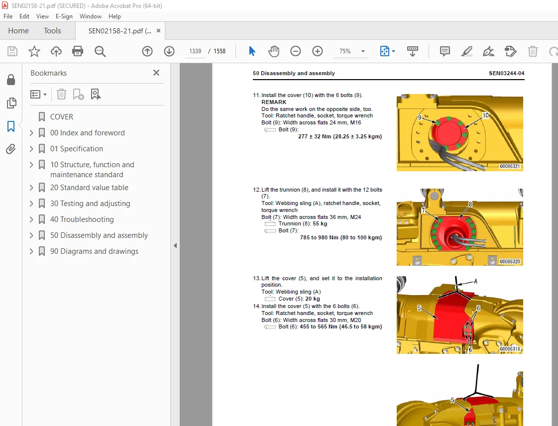
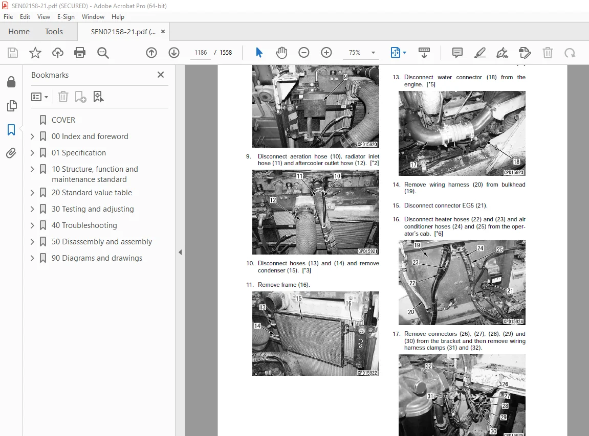
Removal and installation of recoil spring assembly 1326
Disassembly and assembly of recoil spring assembly 1341
Removal and installation of idler assembly 1343
Disassembly and assembly of idler assembly 1345
Removal and installation of track roller assembly 1348
Disassembly and assembly of track roller assembly 1352
Removal and installation of carrier roller assembly 1355
Disassembly and assembly of carrier roller assembly 1356
Removal and installation of 1st bogie assembly 1359
Removal and installation of 2nd, 3rd and 4th bogie assembly 1371
Disassembly and assembly of bogie assembly 1383
Undercarriage and frame, Part 2 1387
Expanding and installing track shoe assembly 1388
Whole disassembly and whole assembly of track shoe assembly 1391
Removal and installation of pivot shaft assembly 1413
Removal and installation of equalizer bar assembly 1414
Disassembly and assembly of equalizer bar bushing 1417
Open and close front under guard 1419
Open and close rear under guard 1423
Remove and install front under guard assembly 1427
Remove and install rear under guard assembly 1437
Hydraulic system 1449
Removal and installation of work equipment pump assembly 1450
Removal and installation of power train and steering lubricating oil pump assembly 1452
Removal and installation of fan pump assembly 1454
Removal and installation of control valve assembly 1456
Disassembly and assembly of work equipment control valve assembly 1460
Disassembly and assembly of hydraulic cylinder assembly 1461
Work equipment 1469
Removal and installation of blade assembly 1470
Removal and installation of blade lift cylinder assembly 1472
Disassembly and assembly of ripper assembly 1480
Cab and its attachments 1485
Removal and installation of ROPS guard 1486
Removal and installation of operator’s cab assembly 1487
Removal and installation of operator’s cab glass (Stuck glass) 1489
Removal and installation of air conditioner unit assembly 1498
Removal and installation of floor frame assembly 1501
Disassembly and assembly of operator’s seat isolator 1506
Electrical system 1509
Removal and installation of transmission controller assembly 1510
Removal and installation of steering controller assembly 1511
Removal and installation of engine controller assembly 1512
Removal and installation of monitor panel assembly 1513
90 Diagrams and drawings 1515
Hydraulic diagrams and drawings 1515
Hydraulic circuit diagram 1517
Power train hydraulic circuit diagram 1519
Electrical diagrams and drawings 1523
Electrical circuit diagram (1/13) 1525
Electrical circuit diagram (2/13) 1527
Electrical circuit diagram (3/13) 1529
Electrical circuit diagram (4/13) 1531
Electrical circuit diagram (5/13) 1533
Electrical circuit diagram (6/13) 1535
Electrical circuit diagram (7/13) 1537
Electrical circuit diagram (8/13) 1539
Electrical circuit diagram (9/13) 1541
Electrical circuit diagram (10/13) 1543
Electrical circuit diagram (11/13) 1545
Electrical circuit diagram (12/13) 1547
Electrical circuit diagram (13/13) 1549
Electrical circuit diagram for inside cab 1551
Air conditioner unit electrical circuit diagram 1553
Connectors table and arrangement drawing 1555
DESCRIPTION:
Komatsu D275A-5R Bulldozer Shop Manual SEN02158-21 – PDF DOWNLOAD
SERIAL NUMBERS 35001 and up
How to read the shop manual
1. Composition of shop manual
This shop manual contains the necessary technical information for services performed in a workshop.
For ease of understanding, the manual is divided into the following sections.
00. Index and foreword
This section explains the shop manuals list, table of contents, safety, and basic information.
01. Specification
This section explains the specifications of the machine.
10. Structure, function and maintenance standard
This section explains the structure, function, and maintenance standard values of each component.
The structure and function sub-section explains the structure and function of each component. It
serves not only to give an understanding of the structure, but also serves as reference material for
troubleshooting. The maintenance standard sub-section explains the criteria and remedies for disassembly
and service.
20. Standard value table
This section explains the standard values for new machine and judgement criteria for testing,
adjusting, and troubleshooting. This standard value table is used to check the standard values in
testing and adjusting and to judge parts in troubleshooting.
30. Testing and adjusting
This section explains measuring instruments and measuring methods for testing and adjusting, and
method of adjusting each part. The standard values and judgement criteria for testing and adjusting
are explained in Testing and adjusting.
40. Troubleshooting
This section explains how to find out failed parts and how to repair them. The troubleshooting is
divided by failure modes. The “S mode” of the troubleshooting related to the engine may be also
explained in the Chassis volume and Engine volume. In this case, see the Chassis volume.
50. Disassembly and assembly
This section explains the special tools and procedures for removing, installing, disassembling, and
assembling each component, as well as precautions for them. In addition, tightening torque and
quantity and weight of coating material, oil, grease, and coolant necessary for the work are also
explained.
90. Diagrams and drawings (chassis volume)/Repair and replacement of parts (engine volume)
q Chassis volume
This section gives hydraulic circuit diagrams and electrical circuit diagrams.
q Engine volume
This section explains the method of reproducing, repairing, and replacing parts.
S.V 29/12/24


