Komatsu BULLDOZER D51EX -24 D51PX-24 Shop Manual SEN06617-13 – PDF
$37.95
Komatsu BULLDOZER D51EX -24 D51PX-24 Shop Manual SEN06617-13 – PDF DOWNLOAD
SERIAL NUMBERS D51EX-10001
D51PX-10001 and up
Description
Komatsu BULLDOZER D51EX -24 D51PX-24 Shop Manual SEN06617-13 – PDF DOWNLOAD
FILE DETAILS:
Komatsu BULLDOZER D51EX -24 D51PX-24 Shop Manual SEN06617-13 – PDF DOWNLOAD
Language : English
Pages :2844
Downloadable : Yes
File Type : PDF
IMAGES PREVIEW OF THE MANUAL:
![]()
![]()
![]()
DESCRIPTION:
Komatsu BULLDOZER D51EX -24 D51PX-24 Shop Manual SEN06617-13 – PDF DOWNLOAD
SERIAL NUMBERS D51EX-10001
D51PX-10001 and up
How to Read the Shop Manual
• Some of the attachments and options described in this shop manual may not be available in some areas. If
they are required, consult your Komatsu distributor.
• The materials and specifications are subject to change without notice.
• Shop Manuals are available for “machine part” and “engine part”. For the engine unit, see the shop manual
for the machine which has the same engine model.
• Actual machine may differ from the images which are contained in this manual. A typical model is shown in
the illustrations of this shop manual.
• The caution lamps, pilot lamps, and symbols of the switches on the machine monitor can be different in
accordance with the machine.
• For details of the symbols shown on the machine monitor, see Structure and Operation, “Caution
Lamps Shown on Machine Monitor” and “Pilot Lamps Shown on Machine Monitor”.
• For details of the switches of the machine monitor, see Testing and Adjusting, “Set and Operate Machine
Monitor”.
• For details of the switches, see the “Operation and Maintenance Manual”.
• All “AdBlue/DEF” shown on the machine monitor is referred to as “DEF” in the shop manual. Some machine
monitors installed to the product show “DEF” as “AdBlue/DEF” in the service mode. Thus, be sure to recognize
that “DEF” and “AdBlue/DEF” are the same when you read the shop manual.
REMARK
The illustrations in the shop manual reproduce the display of the machine monitor. They are not always the
same as the terminology in the shop manual.
Composition of the Shop Manual
This shop manual contains technical information necessary to perform services in workshops. It is divided into
the following chapters for the ease of use.
00 Index and Foreword
This section describes the index, foreword, safety, and basic information.
01 Specification
This section describes the specifications of the machine.
10 Structure and Function
This section describes the structure and operation of each component with respect to each system. “Structure
and Function” is helpful in not only understanding the structure of each component but performing troubleshooting.
20 Standard Value Table
This section describes the standard values for new machine and failure criteria for testing and adjusting, and
troubleshooting. Use the standard values table to check the standard values for testing and adjusting, and judge
troubles in troubleshooting.
30 Testing and Adjusting
This section describes the measuring tools and measuring methods for testing and adjusting as well as the adjusting
method of each part. The standard values and repair limit for TESTING AND ADJUSTING are described
in “Standard Value Table”.
40 Troubleshooting
This section describes troubleshooting of failure part and its remedy method on the occurrence of the failure.
Descriptions of troubleshooting are sorted by failure mode.
This section describes the special tools, work procedures, and safety precautions necessary for removal, installation,
disassembly, and assembly of the components and parts. In addition, tightening torques, quantity, and
weight of the coating materials, lubricants, and coolant necessary to these works are shown.
60 Maintenance Standard
This section describes the maintenance standard value of each component. The maintenance standard shows
the criteria and remedies for disassembly and assembly.
80 Others
This section describes the structure and function, testing and adjusting, and troubleshooting for all of the other
components or equipment which cannot be separately classified in the appendix.
90 Circuit Diagrams
This section describes hydraulic circuit diagrams and electrical circuit diagrams.
Symbols
Important safety and quality portions are marked with the following symbols so that shop manual is used effectively.
TABLE OF CONTENTS:
Komatsu BULLDOZER D51EX -24 D51PX-24 Shop Manual SEN06617-13 – PDF DOWNLOAD
SERIAL NUMBERS D51EX-10001
D51PX-10001 and up
Cover 1
00 Index and Foreword 3
Index 4
Abbreviation List 20
Foreword, Safety, Basic Information 26
How to Read the Shop Manual 26
Safety Notice for Operation 28
Precautions to Prevent Fire 36
Procedures If Fire Occurs 38
Precautions When You Discard Waste Materials 39
Procedures for Exhaust Gas Regulations 40
Precautions for DEF 41
General Character and Precautions for Handling 41
Precautions When You Add 41
Precautions for Storage 41
Precautions for Fire Hazard and Leakage 41
Other Precautions 41
Store DEF 42
Precautions When You Handle Hydraulic Equipment 43
Precautions When You Disconnect and Connect Pipings 46
Precautions When You Handle Electrical Equipment 53
Precautions When You Handle Fuel System Equipment 55
Precautions When You Handle Intake System Equipment 56
Practical Use of KOMTRAX 57
Disconnect and Connect Push-Pull Type Coupler 58
How to Disconnect and Connect Type 1 Push-Pull Type Coupler 58
How to Disconnect and Connect Type 2 Push-Pull Type Coupler 59
How to Disconnect and Connect Type 3 Push-Pull Type Coupler 60
Precautions for Disconnection and Connection of Connectors 62
Disconnect and Connect Deutsch Connector 66
How to Disconnect and Connect Slide Lock Type Connector 67
Disconnect and Connect Connector with Lock to Pull 69
Disconnect and Connect Connector with Lock to Push 70
Disconnect and Connect Connector with Housing to Rotate 72
How to Read the Codes for Electric Cable 73
Explanation of Terms for Maintenance Standard 77
Standard Tightening Torque Table 80
Conversion Table 87
01 Specification 93
Table of Contents 94
Abbreviation List 95
Specifications 101
Specification Drawing 101
Specification Drawing: D51EX-24 101
Specification Drawing: D51PX-24 103
Specifications 105
Specification: D51EX-24 105
Specification: D51PX-24 110
Weight Table 115
Weight Table: D51EX-24 115
Weight Table: D51PX-24 117
Fuel, Coolant, Lubricants (For North America) 119
How to Use Fuel, Coolant and Lubricants by Ambient Temperature 119
Fuel, Coolant, Lubricants (For European Union) 121
How to Use Fuel, Coolant and Lubricants by Ambient Temperature 121
10 Structure and Function 123
Table of Contents 124
Abbreviation List 127
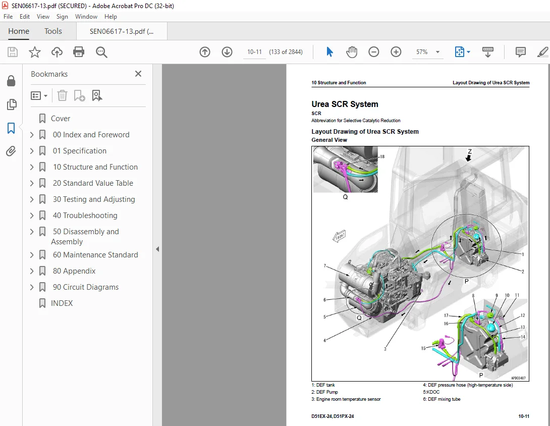
Urea SCR System 133
Layout Drawing of Urea SCR System 133
Urea SCR System Diagram 135
Function of Urea SCR System 136
Function of DEF System 136
Inducement Strategy 139
Component Parts of Urea SCR System 153
DEF Mixing Tube 153
SCR Assembly 154
DEF Tank 156
DEF Pump 158
DEF Injector 159
DEF Hose 160
DEF Tank Heating Valve 161
Boot-up System 162
Layout Drawing of Boot-up System (Machine with KOMTRAX Terminal) 162
Layout Drawing of Boot-up System (Machine with Gateway Function Controller) 163
System Operating Lamp System 164
System Diagram of System Operating Lamp System (Machine with KOMTRAX Terminal) 164
System Diagram of System Operating Lamp System (Machine with Gateway Function Controller) 164
Function of System Operating Lamp System (Machine with KOMTRAX Terminal) 164
Function of System Operating Lamp System (Machine with Gateway Function Controller) 165
Battery Disconnect Switch 167
Function of Battery Disconnect Switch 167
Engine System 168
Layout Drawing of Engine System 168
Engine Control System 170
Layout of Engine Control System (Machine with KOMTRAX Terminal) 170
Layout of Engine Control System (Machine with Gateway Function Controller) 172
System Diagram of Engine Control System (Machine with KOMTRAX Terminal) 174
System Diagram of Engine Control System (Machine with Gateway Function Controller) 176
Function of Engine Control System (Machine with KOMTRAX Terminal) 178
Function of Engine Control System (Machine with Gateway Function Controller) 180
Automatic Idle Stop System 182
Automatic Idle Stop System Diagram (Machine with KOMTRAX Terminal) 182
System Diagram of Automatic Idle Stop System (Machine with Gateway Function Controller) 183
Function of Automatic Idle Stop System 183
Component Parts of Engine System 186
Damper 186
VGT 187
EGR System 190
EGR Valve 192
EGR Cooler 194
KCCV System 196
KCCV Ventilator 198
KDOC 200
Cooling System 203
Layout Drawing of Cooling System 203
Specifications of Cooling System 204
Cooling Fan Control System 205
System Diagram of Cooling Fan Control System 205
Function of Cooling Fan Control System 206
Component Parts of Cooling System 208
Cooling Fan Motor 208
Hydraulic Oil Cooler Bypass and HST Charge Safety Valve 213
Hydraulic Oil Cooler Bypass Valve 214
HST Charge Safety Valve 215
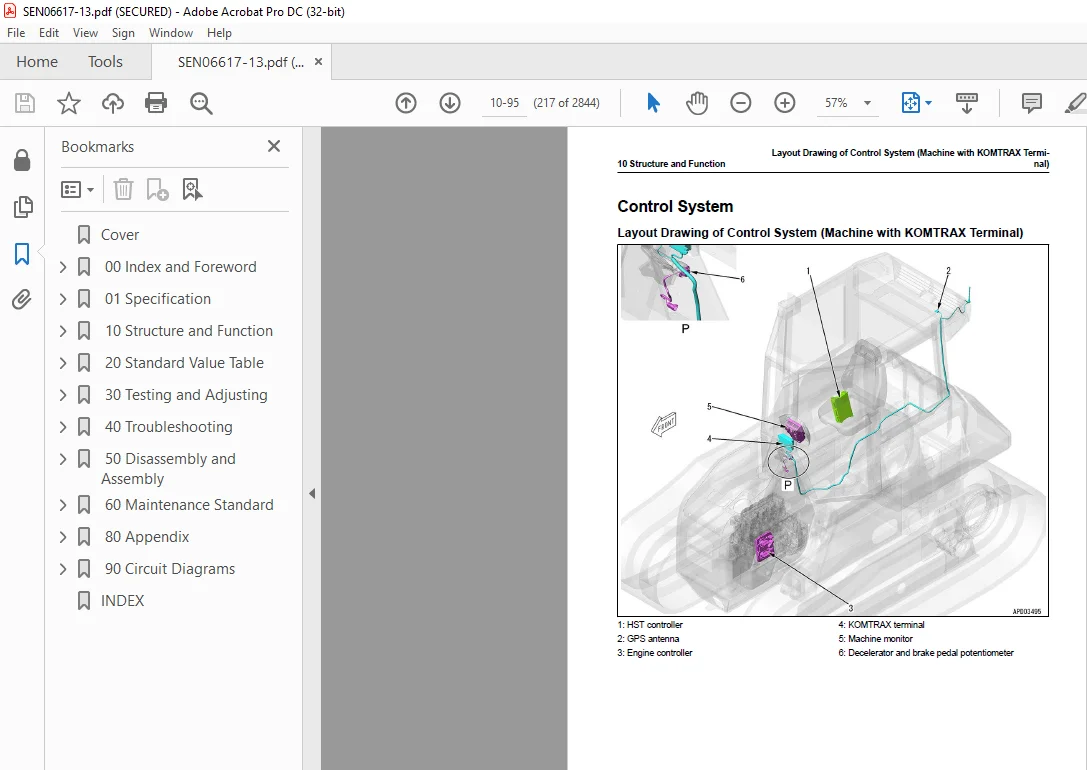
Control System 217
Layout Drawing of Control System (Machine with KOMTRAX Terminal) 217
Layout Drawing of Control System (Machine with Gateway Function Controller) 218
Machine Monitor System 219
System Diagram of Machine Monitor System (Machine with KOMTRAX Terminal) 219
System Diagram of Machine Monitor System (Machine with Gateway Function Controller) 220
Function of Machine Monitor System 220
KOMTRAX System 221
KOMTRAX System Diagram (Machine with KOMTRAX Terminal) 221
System Diagram of KOMTRAX System (Machine with Gateway Function Controller) 221
Function of KOMTRAX System 222
Component Parts of Control System 223
Machine Monitor 223
KOMTRAX Terminal 238
Gateway Function Controller 240
Communication Terminal 243
HST Controller 245
Engine Controller 249
Fuel Control Dial 256
Decelerator and Brake Potentiometer 258
Hydraulic System 260
Layout Drawing of Hydraulic System 260
CLSS 261
Structure of CLSS 261
Function of CLSS 262
Component Parts of Hydraulic System 264
Hydraulic Tank 264
Work Equipment and Cooling Fan Pump 266
LS Valve 274
PC Valve 275
Control Valve 278
Power Train System 296
Layout Drawing of HST System 296
Operation of HST System 297
Steering and Brake Control System 299
Layout Drawing of Steering and Brake Control System 299
Function of Steering and Brake Control System 299
HST Control System 301
System Diagram of HST Control System 301
Gear Shift Control Function 302
Engine Low Speed Matching Control Function 305
HST Pump and Motor Sequence Control Function 306
Deceleration and Brake Control Function 307
Gear Shift Control Function by Load 309
Turn Control Function 309
Straight Travel Correction Control Function 310
Parking Brake Control System 312
System Diagram of Parking Brake Control System 312
Function of Parking Brake Control System 313
Operation of Parking Brake Control System 314
Component Parts of Power Train System 315
HST Pump 315
HST Charge Pump 330
HST Motor 331
Final Drive 344
Electric Steering Electric Lever 348
Work Equipment System 351
Work Equipment Control 351
Layout Drawing of Work Equipment Control 351
Function of Work Equipment Control 352
Layout Drawing of Front Work Equipment 353
Layout Drawing of Fixed Multi-Shank Ripper 354
Component Parts of Work Equipment System 355
Ripper PPC Valve 355
5-Spool EPC and Solenoid Valve 359
Pilot Circuit Accumulator 365
Quick Drop Valve 366
Piston Valve 368
Electric Blade Control Lever 369
Undercarriage and Frame 371
Main Frame 371
Structure of Main Frame 371
Suspension 372
Structure of Suspension 372
Specifications of Suspension 373
Function of Suspension 374
Track Frame and Idler Cushion 375
Structure of Track Frame and Idler Cushion 375
Function of Track Frame and Idler Cushion 376
Work Equipment 377
Structure of Front Work Equipment 377
Structure of Fixed Multi-Shank Ripper 378
CAB Related Parts 379
ROPS CAB 379
Structure of ROPS CAB (Machine with KOMTRAX Terminal) 379
Structure of ROPS CAB (Machine with Gateway Function Controller) 380
Function of ROPS CAB 381
CAB Mount 382
Structure of CAB Mount 382
Function of CAB Mount 382
20 Standard Value Table 383
Table of Contents 384
Abbreviation List 385
Standard Value Table for Engine 391
Standard Value Table for Engine: D51EX-24 391
Standard Value Table for Engine: D51PX-24 395
Standard Value Table for Machine 399
Standard Value Table for Machine: D51EX-24 399
Standard Value Table for Machine: D51PX-24 415
Machine Posture and Procedures to Measure Performance 429
30 Testing and Adjusting 431
Table of Contents 432
Precautions Before Work 435
Abbreviation List 436
Related Information on Testing and Adjusting 442
Tools for Testing and Adjusting 442
Sketch of Tools for Testing and Adjusting 449
Engine and Cooling System 452
Examine Engine Speed 452
How to Examine Engine Speed 452
Examine Boost Pressure 454
How to Examine Boost Pressure 454
Examine Exhaust Gas Color 455
How to Examine Exhaust Gas Color with the Handy Smoke Checker 455
How to Examine Exhaust Gas Color with Smoke Meter 456
Examine and Adjust Valve Clearance 457
Check Valve Clearance 457
Adjust Valve Clearance 458
Examine Compression Pressure 459
How to Examine Compression Pressure 459
Examine Blowby Pressure 464
How to Examine Blowby Pressure 464
Examine Engine Oil Pressure 466
How to Examine Engine Oil Pressure 466
Visual Check Inside of EGR Valve 467
How to do the Visual Check Inside of EGR Valve 467
Clean Inside of EGR Valve 469
How to Clean Inside of EGR Valve 469
Examine Fuel Pressure 472
How to Examine Fuel Pressure 473
Examine Fuel Discharge, Return and Leakage 477
How to Examine Fuel Discharge, Return, and Leakage 478
Bleed Air from Fuel System 483
How to Bleed Air from Fuel System 483
Examine Fuel Circuit for Leakage 484
How to Examine Fuel System for Leakage 484
Handle Cylinder Cut-out Mode Operation 486
Handle No-Injection Cranking Operation 487
Examine KDOC, SCR and Muffler Stack for Looseness and Damage 488
How to Examine KDOC, SCR and Muffler Stack for Looseness and Damage 488
Examine Installed Condition of Cylinder Heads and Manifolds 489
How to Examine Installed Condition of Cylinder Heads and Manifolds 489
Examine Engine Piping for Damage and Looseness 490
How to Examine Engine Piping for Damage and Looseness 490
Write Correction for Ash in Soot Accumulation to Engine Controller 491
How to Write Correction for Ash in Soot Accumulation to Engine Controller 491
Examine SCR Related Functions 492
Examine DEF Pump Raised Pressure 496
Examine Injection Volume from DEF Injector 499
Examine DEF Line Heater Relay 1 503
Examine DEF Line Heater Relay 2 506
Examine DEF Pump Heater Relay 509
Examine DEF Tank Heater Valve 513
Examine SCR Denitration Efficiency 517
Clean DEF Tank 520
How to Clean DEF Tank 520
Clean DEF Tank Mounting Part 524
How to Clean DEF Tank Mounting Part 524
Clean DEF Pump 525
How to Clean DEF Pump 525
Power Train 531
Examine and Adjust HST Oil Pressure 531
Examine HST Oil Pressure 531
Adjust HST Oil Pressure 533
Bleed Air from HST Pump 536
How to Bleed Air from HST Pump 536
Bleed Air from Servo Valve of HST Pump 536
Examine Outlet Pressure of Solenoid Valve 538
How to Examine Outlet Pressure of Solenoid Valve 538
Examine Travel Deviation 542
How to Examine Travel Deviation 542
Examine Brake Performance Simply 544
How to Examine Brake Performance Simply 544
Examine and Adjust Deceleration/Brake Pedal 545
How to Examine Deceleration/Brake Pedal 545
How to Adjust Deceleration/Brake Pedal 547
Adjust Parking Brake Lever 549
How to Adjust Parking Brake Lever 549
Move Machine When It Cannot Travel 551
Move Machine with Hydraulic Type Parking Brake Release System 551
Move Machine After You Remove Final Drive Shaft 553
Undercarriage and Frame 554
Examine and Adjust Idler Clearance 554
How to Adjust Idler Clearance Horizontally 554
How to Adjust Idler Clearance Vertically 555
Examine Sprocket Wear 556
How to Examine Sprocket Wear 556
Examine and Adjust Track Tension 557
How to Examine Track Tension 557
How to Adjust Track Tension 557
Hydraulic System 559
Release Remained Pressure in Hydraulic Circuit 559
How to Release Remained Pressure in Hydraulic System 559
Examine and Adjust Work Equipment Circuit Oil Pressure 560
How to Examine Work Equipment Circuit Oil Pressure 560
Adjust Work Equipment Circuit Oil Pressure 561
Examine and Adjust Oil Pressure in Control Circuit 563
Examine Oil Pressure in Control Circuit 563
Adjust Oil Pressure in Control Circuit 564
Examine Outlet Pressure of EPC Solenoid Valve 565
How to Examine Outlet Pressure of EPC Solenoid Valve 565
Bleed Air from Work Equipment and Cooling Fan Pump 567
How to Bleed Air from Work Equipment and Cooling Fan Pump 567
Examine Cooling Fan Speed 568
How to Examine Cooling Fan Speed 568
Examine Cooling Fan Circuit Oil Pressure 569
How to Examine Cooling Fan Circuit Oil Pressure 569
Examine Parts Which Cause Hydraulic Drift of Work Equipment 571
How to Examine Parts Which Cause Hydraulic Drift of Blade Lift Cylinder 571
How to Examine the Parts Which Cause Hydraulic Drift of Blade Tilt Cylinder 571
How to Examine the Parts Which Cause Hydraulic Drift of Ripper Lift Cylinder 572
Examine Oil Leakage from Work Equipment Cylinder 573
How to Examine Internal Oil Leakage of Work Equipment Cylinder 573
Bleed Air from Work Equipment Cylinders 576
Bleed Air from Work Equipment Cylinder 576
Work Equipment 577
Adjust Work Equipment Lock Lever 577
How to Adjust Work Equipment Lock Lever 577
Examine and Adjust Play of Blade Electric Lever 579
How to Examine Play of Blade Electric Lever 581
Adjust Play of Blade Electric Lever 581
Replace Universal Joint 583
Electrical System 589
Set and Operate Machine Monitor 589
Operator Mode 593
Function to Show Technician Identification Status Screen 593
Function to Show Operator Identification Input Screen 593
Examine Function by LCD (Liquid Crystal Display) 594
Examine Function of Service Meter 594
Usage Limitation and Change Maintenance Password 594
Service Mode 597
How to Operate Service Mode 597
How to See Pre-defined Monitoring Information 599
How to Examine Self-Define Monitor Information 605
Abnormality Record Menu 615
How to See Maintenance Record 619
Maintenance Mode Setting 620
Set Phone Number Entry 624
Default Menu 626
Diagnostic Tests Menu 633
Adjustment Menu 641
No-Injection Cranking Operation 698
KOMTRAX Settings Menu 700
Show Service Message 704
Start Up KOMTRAX Terminal (Machine with KOMTRAX Terminal) 706
Stop Use of KOMTRAX Terminal (Machine with KOMTRAX Terminal) 711
Start Up KOMTRAX System (Machine with Gateway Function Controller) 713
Stop Use of KOMTRAX System (Machine with Gateway Function Controller) 719
Adjust After Replacement of HST Controller 721
How to Adjust After Replacement of HST Controller 721
Adjust After Replacement of Electric and Hydraulic Equipment 727
Adjust Rearview Camera Angle 729
How to Adjust Rearview Camera Angle 729
Handle Voltage Circuit of Engine Controller 730
Handle Battery Disconnect Switch (Machine with KOMTRAX Terminal) 731
Handle Battery Disconnect Switch (Machine with Gateway Function Controller) 732
Examine Diodes 733
Examine Diodes by Digital Tester 733
How to Examine Diodes by Analog Tester 733
Pm Clinic 734
Pm Clinic Service 734
Pm Clinic Check Sheet: D51EX-24 736
Pm Clinic Check Sheet: D51PX-24 744
Pm Clinic Check Sheet for Undercarriage: D51EX-24 751
Pm Clinic Check Sheet for Undercarriage: D51PX-24 755
40 Troubleshooting 759
Table of Contents 760
Precautions Before Work 770
Abbreviation List 771
Related Information to Troubleshooting 777
General Troubleshooting Points 777
Troubleshooting Points for Urea SCR System 778
Sequence of Events in Troubleshooting 790
Checks Before Troubleshooting 792
Inspection Procedure Before Troubleshooting 794
Walk-Around Check 794
Test in Accordance with Testing Procedure 796
Examine Fuel Level and Type 796
Examine for Impure Ingredient in Fuel 796
Examine DEF Level and Type 797
Examine Fuel Prefilter 797
Examine Fuel Main Filter 799
Examine Engine Oil Level (Oil Quantity in Oil Pan) and Type 800
Examine Coolant Level (Reservoir Tank) 802
Examine Air Cleaner Clogging 802
Clean Outer Element 803
Replace Element 805
Examine Hydraulic Oil Level 806
Examine Hydraulic Oil Strainer 807
Examine Oil Level in Final Drive Case 810
Bleed Air from Fuel System 811
Bleed Air from Hydraulic System 811
How to Examine Electric Equipment 811
Preparation for Troubleshooting of Electrical System 818
Procedure for Troubleshooting 825
Symptom and Troubleshooting Numbers 828
Information Shown in Troubleshooting Table 831
Diagnose Open Circuit of Hydraulic Pressure Sensor System Wiring Harness 833
Connector List and Layout (Machine with KOMTRAX Terminal) 836
Connector List and Layout (Machine with Gateway Function Controller) 850
Connector Contact Connection Table 864
T-Branch Box and T-Branch Adapter Table 904
Fuse Location Table (Machine with KOMTRAX Terminal) 910
Fuse Location Table (Machine with Gateway Function Controller) 914
Precautions When You Replace KDOC 918
Failure Code Table 919
Troubleshooting by Failure Code (Display of Code) 937
Failure Code [6091NX] 937
Failure Code [989L00] 939
Failure Code [989M00] 940
Failure Code [989N00] 941
Failure Code [A1U0N3] 942
Failure Code [A1U0N4] 944
Failure Code [A900FR] 946
Failure Code [A900N6] 947
Failure Code [A900NY] 948
Failure Code [AA10NX] 949
Failure Code [AB00KE] 951
Failure Code [AQ10MB] 953
Failure Code [AQ10N3] 955
Failure Code [AS00R2] 957
Failure Code [AS00R3] 958
Failure Code [AS00R4] 959
Failure Code [AS00R5] 960
Failure Code [AS00R6] 961
Failure Code [AS00ZK] 962
Failure Code [AS10KM] 963
Failure Code [AS10NR] 964
Failure Code [AS10NT] 965
Failure Code [B@BAZG] 966
Failure Code [B@BCNS] 967
Failure Code [B@CRNS] 968
Failure Code [B@CRZG] 969
Failure Code [CA115] 970
Failure Code [CA122] 971
Failure Code [CA123] 973
Failure Code [CA131] 975
Failure Code [CA132] 977
Failure Code [CA144] 979
Failure Code [CA145] 981
Failure Code [CA153] 983
Failure Code [CA154] 985
Failure Code [CA187] 987
Failure Code [CA221] 989
Failure Code [CA222] 991
Failure Code [CA227] 993
Failure Code [CA234] 995
Failure Code [CA238] 996
Failure Code [CA239] 997
Failure Code [CA249] 998
Failure Code [CA256]1000
Failure Code [CA271]1002
Failure Code [CA272]1004
Failure Code [CA295]1006
Failure Code [CA322]1007
Failure Code [CA324]1009
Failure Code [CA331]1011
Failure Code [CA332]1013
Failure Code [CA343]1015
Failure Code [CA351]1016
Failure Code [CA352]1017
Failure Code [CA356]1019
Failure Code [CA357]1021
Failure Code [CA386]1023
Failure Code [CA428]1024
Failure Code [CA429]1026
Failure Code [CA435]1028
Failure Code [CA441]1030
Failure Code [CA442]1032
Failure Code [CA451]1033
Failure Code [CA452]1035
Failure Code [CA488]1037
Failure Code [CA515]1038
Failure Code [CA516]1040
Failure Code [CA553]1042
Failure Code [CA555]1043
Failure Code [CA556]1044
Failure Code [CA559]1045
Failure Code [CA595]1048
Failure Code [CA687]1050
Failure Code [CA689]1052
Failure Code [CA691]1055
Failure Code [CA692]1057
Failure Code [CA697]1059
Failure Code [CA698]1060
Failure Code [CA731]1061
Failure Code [CA778]1063
Failure Code [CA1117]1068
Failure Code [CA1664]1070
Failure Code [CA1669]1072
Failure Code [CA1673]1073
Failure Code [CA1677]1074
Failure Code [CA1678]1075
Failure Code [CA1682]1076
Failure Code [CA1683]1078
Failure Code [CA1684]1080
Failure Code [CA1686]1082
Failure Code [CA1691]1083
Failure Code [CA1694]1085
Failure Code [CA1695]1087
Failure Code [CA1696]1088
Failure Code [CA1712]1090
Failure Code [CA1713]1093
Failure Code [CA1714]1095
Failure Code [CA1715]1096
Failure Code [CA1776]1097
Failure Code [CA1777]1100
Failure Code [CA1843]1103
Failure Code [CA1844]1105
Failure Code [CA1885]1108
Failure Code [CA1887]1110
Failure Code [CA1896]1112
Failure Code [CA1898]1116
Failure Code [CA1938]1118
Failure Code [CA1942]1120
Failure Code [CA1961]1121
Failure Code [CA1962]1122
Failure Code [CA2185]1123
Failure Code [CA2186]1125
Failure Code [CA2198]1127
Failure Code [CA2272]1129
Failure Code [CA2288]1131
Failure Code [CA2311]1132
Failure Code [CA2349]1133
Failure Code [CA2353]1135
Failure Code [CA2357]1137
Failure Code [CA2373]1138
Failure Code [CA2374]1140
Failure Code [CA2375]1142
Failure Code [CA2376]1144
Failure Code [CA2387]1147
Failure Code [CA2554]1148
Failure Code [CA2555]1150
Failure Code [CA2556]1153
Failure Code [CA2634]1156
Failure Code [CA2635]1158
Failure Code [CA2636]1159
Failure Code [CA2637]1161
Failure Code [CA2771]1163
Failure Code [CA2961]1167
Failure Code [CA2973]1168
Failure Code [CA2976]1169
Failure Code [CA3142]1171
Failure Code [CA3143]1172
Failure Code [CA3144]1173
Failure Code [CA3146]1175
Failure Code [CA3147]1176
Failure Code [CA3148]1177
Failure Code [CA3151]1179
Failure Code [CA3165]1184
Failure Code [CA3228]1186
Failure Code [CA3229]1188
Failure Code [CA3231]1190
Failure Code [CA3232]1192
Failure Code [CA3235]1196
Failure Code [CA3239]1198
Failure Code [CA3241]1201
Failure Code [CA3242]1204
Failure Code [CA3251]1207
Failure Code [CA3313]1209
Failure Code [CA3314]1210
Failure Code [CA3315]1211
Failure Code [CA3419]1213
Failure Code [CA3421]1215
Failure Code [CA3497]1217
Failure Code [CA3498]1218
Failure Code [CA3545]1219
Failure Code [CA3547]1221
Failure Code [CA3558]1222
Failure Code [CA3559]1224
Failure Code [CA3562]1226
Failure Code [CA3563]1228
Failure Code [CA3567]1231
Failure Code [CA3568]1235
Failure Code [CA3571]1239
Failure Code [CA3572]1241
Failure Code [CA3574]1243
Failure Code [CA3575]1245
Failure Code [CA3577]1247
Failure Code [CA3578]1249
Failure Code [CA3582]1251
Failure Code [CA3583]1256
Failure Code [CA3596]1258
Failure Code [CA3649]1262
Failure Code [CA3681]1264
Failure Code [CA3682]1269
Failure Code [CA3713]1274
Failure Code [CA3717]1277
Failure Code [CA3718]1278
Failure Code [CA3724]1279
Failure Code [CA3725]1280
Failure Code [CA3741]1283
Failure Code [CA3748]1284
Failure Code [CA3755]1286
Failure Code [CA3866]1288
Failure Code [CA3868]1291
Failure Code [CA4152]1295
Failure Code [CA4155]1299
Failure Code [CA4156]1302
Failure Code [CA4157]1305
Failure Code [CA4159]1307
Failure Code [CA4164]1308
Failure Code [CA4165]1310
Failure Code [CA4166]1312
Failure Code [CA4168]1313
Failure Code [CA4169]1316
Failure Code [CA4171]1318
Failure Code [CA4249]1320
Failure Code [CA4251]1322
Failure Code [CA4261]1324
Failure Code [CA4277]1327
Failure Code [CA4459]1331
Failure Code [CA4461]1333
Failure Code [CA4533]1336
Failure Code [CA4534]1337
Failure Code [CA4731]1338
Failure Code [CA4732]1339
Failure Code [CA4739]1340
Failure Code [CA4768]1341
Failure Code [CA4769]1343
Failure Code [CA4842]1345
Failure Code [CA4952] (Machine with KOMTRAX Terminal)1348
Failure Code [CA4952] (Machine with Gateway Function Controller)1350
Failure Code [CA5115]1352
Failure Code [CA5179]1355
Failure Code [CA5181]1357
Failure Code [CA5387]1359
Failure Code [CA5388]1361
Failure Code [CA5389]1364
Failure Code [CA5391]1366
Failure Code [CA5392]1370
Failure Code [CA5393]1372
Failure Code [CA5394]1375
Failure Code [CA5395]1378
Failure Code [CA5396]1381
Failure Code [CA5631]1382
Failure Code [CA5632]1384
Failure Code [CA5938]1385
Failure Code [D130KA]1387
Failure Code [D130KB]1390
Failure Code [D130KY]1392
Failure Code [D19JKZ]1394
Failure Code [D811MC] (Machine with KOMTRAX Terminal)1397
Failure Code [D811MC] (Machine with Gateway Function Controller)1398
Failure Code [D862KA] (Machine with KOMTRAX Terminal)1399
Failure Code [D862KA] (Machine with Gateway Function Controller)1400
Failure Code [D8ALKA] (Machine with KOMTRAX Terminal)1401
Failure Code [D8ALKA] (Machine with Gateway Function Controller)1403
Failure Code [D8ALKB] (Machine with KOMTRAX Terminal)1405
Failure Code [D8ALKB] (Machine with Gateway Function Controller)1407
Failure Code [D8AQKR] (Machine with KOMTRAX Terminal)1409
Failure Code [D8AQKR] (Machine with Gateway Function Controller)1411
Failure Code [D8G1KT]1413
Failure Code [D8G6KT]1414
Failure Code [DAF0MB]1415
Failure Code [DAF0MC]1416
Failure Code [DAF8KB]1417
Failure Code [DAF9KQ]1419
Failure Code [DAFGMC] (Machine with KOMTRAX Terminal)1420
Failure Code [DAFGMC] (Machine with Gateway Function Controller)1421
Failure Code [DAFLKA] (Machine with KOMTRAX Terminal)1422
Failure Code [DAFLKA] (Machine with Gateway Function Controller)1424
Failure Code [DAFLKB] (Machine with KOMTRAX Terminal)1426
Failure Code [DAFLKB] (Machine with Gateway Function Controller)1428
Failure Code [DAFQKR] (Machine with KOMTRAX Terminal)1430
Failure Code [DAFQKR] (Machine with Gateway Function Controller)1431
Failure Code [DAJ000]1432
Failure Code [DAJ0KQ]1433
Failure Code [DAJ0KT]1434
Failure Code [DAJ0MC]1435
Failure Code [DAJ1KK]1436
Failure Code [DAJ2KK]1438
Failure Code [DAJ5KK]1440
Failure Code [DAJ6KK]1443
Failure Code [DAJLKA] (Machine with KOMTRAX Terminal)1445
Failure Code [DAJLKA] (Machine with Gateway Function Controller)1447
Failure Code [DAJLKB] (Machine with KOMTRAX Terminal)1449
Failure Code [DAJLKB] (Machine with Gateway Function Controller)1451
Failure Code [DAJPMA]1453
Failure Code [DAJQKR] (Machine with KOMTRAX Terminal)1454
Failure Code [DAJQKR] (Machine with Gateway Function Controller)1455
Failure Code [DAJRKR]1456
Failure Code [DB2QKR] (Machine with KOMTRAX Terminal)1457
Failure Code [DB2QKR] (Machine with Gateway Function Controller)1462
Failure Code [DB2RKR]1467
Failure Code [DD12KA]1472
Failure Code [DD12KB]1474
Failure Code [DD13KA]1476
Failure Code [DD13KB]1478
Failure Code [DD14KA]1480
Failure Code [DD14KB]1482
Failure Code [DDKAKA]1484
Failure Code [DDKAKB]1486
Failure Code [DDKFL4]1488
Failure Code [DDKGL4]1490
Failure Code [DDKHKA]1492
Failure Code [DDKHKB]1494
Failure Code [DDNLKA]1496
Failure Code [DDNLKB]1498
Failure Code [DDP6KA]1500
Failure Code [DDP6KB]1503
Failure Code [DDP6MA]1505
Failure Code [DDU1FS]1507
Failure Code [DDU1KA]1509
Failure Code [DDU1KY]1512
Failure Code [DFA4KX]1514
Failure Code [DFA4KZ]1515
Failure Code [DFA4L8]1516
Failure Code [DFA5KA]1517
Failure Code [DFA5KB]1520
Failure Code [DFA6KA]1523
Failure Code [DFA6KB]1526
Failure Code [DFA7KX]1529
Failure Code [DFA7KZ]1530
Failure Code [DFA7L8]1531
Failure Code [DFA8KA]1532
Failure Code [DFA8KB]1535
Failure Code [DFA9KA]1538
Failure Code [DFA9KB]1541
Failure Code [DGS1KA]1544
Failure Code [DGS1KX]1547
Failure Code [DH21KA]1548
Failure Code [DH21KB]1550
Failure Code [DHA4KA]1552
Failure Code [DHH7KA]1554
Failure Code [DHH7KB]1557
Failure Code [DHH8KA]1559
Failure Code [DHH8KB]1562
Failure Code [DHH9KA]1564
Failure Code [DHH9KB]1567
Failure Code [DHHAKA]1569
Failure Code [DHHAKB]1572
Failure Code [DK30KA]1574
Failure Code [DK30KB]1577
Failure Code [DK30KX]1579
Failure Code [DK30KZ]1580
Failure Code [DK30L8]1581
Failure Code [DK31KA]1582
Failure Code [DK31KB]1585
Failure Code [DK40KA]1587
Failure Code [DK40KB]1590
Failure Code [DK55KX]1592
Failure Code [DK55KZ]1593
Failure Code [DK55L8]1594
Failure Code [DK56KA]1595
Failure Code [DK56KB]1598
Failure Code [DK57KA]1600
Failure Code [DK57KB]1603
Failure Code [DLM0KX]1605
Failure Code [DLM1KA]1606
Failure Code [DLM1KB]1608
Failure Code [DLM1MA]1610
Failure Code [DLM2KA]1611
Failure Code [DLM2KB]1613
Failure Code [DLM2MA]1615
Failure Code [DLM3KA]1616
Failure Code [DLM3KB]1618
Failure Code [DLM3MB]1620
Failure Code [DN21FS]1621
Failure Code [DR21KX]1623
Failure Code [DR31KX]1624
Failure Code [DV20KB]1625
Failure Code [DW4BKA]1627
Failure Code [DW4BKB]1629
Failure Code [DW4BKY]1631
Failure Code [DW7BKA]1633
Failure Code [DW7BKB]1635
Failure Code [DW7EKA]1637
Failure Code [DW7EKB]1639
Failure Code [DW7EKY]1641
Failure Code [DWN5KA]1643
Failure Code [DWN5KB]1645
Failure Code [DWN5KY]1647
Failure Code [DXA4KA]1649
Failure Code [DXA4KB]1651
Failure Code [DXA4KY]1653
Failure Code [DXA5KA]1655
Failure Code [DXA5KB]1657
Failure Code [DXA5KY]1659
Failure Code [DXA6KA]1661
Failure Code [DXA6KB]1663
Failure Code [DXA6KY]1665
Failure Code [DXA7KA]1667
Failure Code [DXA7KB]1669
Failure Code [DXA7KY]1671
Failure Code [DXHRKA]1673
Failure Code [DXHRKB]1675
Failure Code [DXHRKY]1677
Failure Code [DXHSKA]1679
Failure Code [DXHSKB]1681
Failure Code [DXHSKY]1683
Failure Code [DXHTKA]1685
Failure Code [DXHTKB]1687
Failure Code [DXHTKY]1689
Failure Code [DXHUKA]1691
Failure Code [DXHUKB]1693
Failure Code [DXHUKY]1695
Failure Code [DXJ4KA]1697
Failure Code [DXJ4KB]1699
Failure Code [DXJCKA]1701
Failure Code [DXJCKB]1703
Failure Code [DXJCKY]1705
Failure Code [DXJDKA]1707
Failure Code [DXJDKB]1709
Failure Code [DXJDKY]1711
Failure Code [DXK1KA]1713
Failure Code [DXK1KB]1715
Failure Code [DXK1KY]1717
Failure Code [DXK2KA]1719
Failure Code [DXK2KB]1721
Failure Code [DXK2KY]1723
Failure Code [F313KA]1725
Failure Code [F313KB]1726
Failure Code [F318KB]1727
Failure Code [F318KY]1728
Troubleshooting of Electrical System (E-Mode)1729
Engine Does Not Start (Engine Does Not Crank)1729
Manual Preheating System Does Not Operate1736
Automatic Preheating System Does Not Operate1739
While Preheating is in Operation, Preheating Monitor Does Not Come On1741
When Starting Switch is Turned to ON Position, Machine Monitor Shows Nothing1743
When Starting Switch is Turned to ON Position (with Engine Stopped), Basic Check Monitor Comes On1747
Air Cleaner Clogging Monitor Comes On in Yellow While Engine is in Operation1748
Charge Level Monitor Comes On in Red While Engine is in Operation1749
Engine Coolant Temperature Monitor Comes On in Red While Engine is in Operation1750
Engine Oil Pressure Monitor Comes On in Red While Engine is in Operation1751
HST Charge Pressure Monitor Comes On in Red While Engine Runs1752
Hydraulic Oil Temperature Monitor Comes On in Red While Engine is in Operation1753
HST Oil Filter Clogging Monitor Comes On in Red While Engine Runs1754
Engine Coolant Temperature Gauge Does Not Show Correct Temperature1755
DEF Level is Not Shown Correctly1756
Fuel Gauge Does Not Show Normally1759
Hydraulic Oil Temperature Gauge Does Not Show Correct Temperature1762
Operation Mode Does Not Change1763
When You Operate Customize Switch Does Not Show Customize Screen1764
When You Change Setting on Customize Screen, Setting of Machine is Not Changed1765
Service Meter is Not Shown While Starting Switch is in OFF Position1766
Service Mode Cannot be Selected1767
Work Equipment Does Not Operate1768
Foot Heater Does Not Operate1770
Horn Does Not Sound1776
Horn Does Not Stop1778
Backup Alarm Does Not Sound1779
Backup Alarm Does Not Stop Operation1780
Headlamp Does Not Come On1781
Rear Lamp Does Not Come On1785
No Wiper Operates1788
Front Wiper Does Not Operate1790
Rear Wiper Does Not Operate1792
Left Door Wiper Does Not Operate1794
Right Door Wiper Does Not Operate1798
Front Washer Does Not Operate1802
Rear Washer Does Not Operate1804
Left Door Washer Does Not Operate1806
Right Door Washer Does Not Operate1808
KOMTRAX System Does Not Operate Correctly1810
Troubleshooting for Hydraulic and Mechanical Systems (H Mode)1811
Information Shown in Troubleshooting Table (H-Mode)1811
Failure Mode and Cause Table1812
RH and LH Tracks Cannot Travel FORWARD and REVERSE (None of the Travel Systems Operate)1818
RH or LH Track Cannot Travel FORWARD and Reverse (One of RH or LH Travel Systems Cannot Operate)1820
RH or LH Track Cannot Travel Forward or Reverse (Only One of the Travel Systems Cannot Operate in One Direction)1822
Travel Speed or Power is Low1824
Speed Range Does Not Change1826
Shock is Large When Machine Moves Off or Stops1827
Travel Deviation is Large1828
Machine Drift on a Slope is Large1831
Engine Speed Drops Largely or Engine Stops1833
Unusual Noise is Heard from Around HST Pump or Motor1835
HST Oil Temperature (Hydraulic Oil Temperature) Increases Too High1837
All Work Equipment Do Not Operate1839
All Work Equipment Speed or Power is Low1841
Blade Lift Speed or Power is Low1842
Blade Tilt Speed or Power is Low1844
Blade Angle Speed or Power is Low1845
Time Lag of Blade Lift is Large1846
Hydraulic Drift of Blade Lift is Large1847
Hydraulic Drift of Tilted Blade is Large1848
Unusual Noise is Heard from Around Work Equipment and Cooling Fan Pump or Control Valve1849
Fan Speed is Abnormal (Too High or Low, or Does Not Rotate)1850
Unusual Noise is Heard from Around Fan1852
Troubleshooting of Engine (S-Mode)1853
Information Shown in Troubleshooting Table (S-Mode)1853
Engine Does Not Crank When Starting Switch is Turned to Start Position1854
Engine Cranks but No Exhaust Smoke Comes Out1855
Fuel is Sprayed but Engine Does Not Start (Misfiring: Engine Cranks but Does Not Start)1856
Engine Startability is Unsatisfactory1858
Engine Does Not Pick Up Smoothly1860
Engine Stops During Operation1862
Engine Does Not Rotate Smoothly1864
Engine Lacks Output (or Lacks Power)1865
Exhaust Smoke is Black1867
Engine Oil Consumption is Excessive1869
Engine Oil Becomes Dirty Quickly1870
Fuel Consumption is Excessive1871
Oil is in Coolant (or Coolant Spurts Back or Coolant Level Goes Down)1872
Engine Oil Pressure Drops1873
Fuel Mixes Into Engine Oil1875
Water Mixes Into Engine Oil (Milky)1876
Coolant Temperature Increases Too High (Overheat)1877
Unusual Noise is Heard1878
Vibration is Excessive1879
Air Cannot be Bled from Fuel Circuit1880
Active Regeneration is Done Frequently1881
Active Regeneration Continues Long1882
White Smoke is Exhausted During Active Regeneration1883
DEF Consumption is Excessive1884
There is an Unusual Smell (Irritating Odor)1886
Foreign Materials Enter DEF (DEF Increases)1887
50 Disassembly and Assembly1889
Table of Contents1890
Precautions Before Work1895
Abbreviation List1896
Related Information on Disassembly and Assembly1902
How to Read This Manual1902
Coating Materials List1903
Special Tool List1908
Sketches of Special Tools1928
Engine and Cooling System1941
Remove and Install Supply Pump Assembly1941
Remove Supply Pump Assembly1941
Install Supply Pump Assembly1951
Remove and Install Injector Assembly1961
How to Remove Injector Assembly1961
How to Install Injector Assembly1972
Remove and Install Cylinder Head Assembly1986
How to Remove Cylinder Head Assembly1986
How to Install Cylinder Head Assembly2005
Remove and Install EGR Valve Assembly2029
Remove EGR Valve Assembly2029
Install EGR Valve Assembly2032
Remove and Install EGR Cooler Assembly2036
How to Remove EGR Cooler Assembly2036
How to Install EGR Cooler Assembly2040
Remove and Install Starter Assembly2044
Remove Starting Motor Assembly2044
Install Starting Motor Assembly2046
Remove and Install Air Conditioner Compressor Belt2049
Remove Air Conditioner Compressor Belt2049
Install Air Conditioner Compressor Belt2053
Remove and Install Alternator Belt2058
Remove Alternator Belt2058
Install Alternator Belt2061
Remove and Install Automatic Tensioner2063
Remove Automatic Tensioner2063
Install Automatic Tensioner2064
Remove and Install Radiator Assembly2066
How to Remove Radiator Assembly2067
How to Install Radiator Assembly2075
Remove and Install Hydraulic Oil Cooler Assembly2083
How to Remove Hydraulic Oil Cooler Assembly2084
How to Install Hydraulic Oil Cooler Assembly2089
Remove and Install Aftercooler Assembly2094
Remove Aftercooler Assembly2095
Install Aftercooler Assembly2101
Remove and Install Cooling Fan Drive Assembly2108
Remove Cooling Fan Drive Assembly2108
Install Cooling Fan Drive Assembly2113
Remove and Install Cooling Fan Motor Assembly2117
Remove Cooling Fan Motor Assembly2117
Install Cooling Fan Motor Assembly2120
Remove and Install Engine and HST Pump Assembly2123
Remove Engine and HST Pump Assembly2123
Install Engine and HST Pump Assembly2134
Remove and Install Engine Front Oil Seal2146
How to Remove Engine Front Oil Seal2146
How to Install Engine Front Oil Seal2148
Remove and Install Engine Rear Oil Seal2150
How to Remove Engine Rear Oil Seal2150
How to Install Engine Rear Oil Seal2151
Remove and Install Engine Hood Assembly2154
How to Remove Engine Hood Assembly2154
How to Install Engine Hood Assembly2158
Remove and Install KDOC Assembly2162
How to Remove KDOC Assembly2162
How to Install KDOC Assembly2168
Remove and Install KDOC and SCR Assembly2175
Remove KDOC and SCR Assembly2176
Install KDOC and SCR Assembly2182
Remove and Install Bellows Pipe Assembly2190
Remove Bellows Pipe Assembly2190
Install Bellows Pipe Assembly2193
Remove and Install Fuel Tank Assembly2197
Remove Fuel Tank Assembly2198
Install Fuel Tank Assembly2205
Remove and Install DEF Tank Assembly2212
How to Remove DEF Tank Assembly2213
How to Install DEF Tank Assembly2223
Remove and Install DEF Tank Sensor Flange Assembly2232
How to Remove DEF Tank Sensor Flange Assembly2232
How to Install DEF Tank Sensor Flange Assembly2234
Remove and Install DEF Tank Sensor2238
Remove DEF Tank Sensor2238
Install DEF Tank Sensor2239
Remove and Install DEF Tank Strainer2246
Remove DEF Tank Strainer2246
Install DEF Tank Strainer2247
Remove and Install SCR Assembly2248
How to Remove SCR Assembly2248
How to Install SCR Assembly2251
Remove and Install KCCV Assembly2254
Remove KCCV Assembly2254
Install KCCV Assembly2255
Remove and Install DEF Mixing Tube2258
Remove DEF Mixing Tube2258
Install DEF Mixing Tube2262
Remove and Install DEF Injector2267
Remove DEF Injector2267
Install DEF Injector2272
Remove and Install DEF Pump2277
Remove DEF Pump2277
Install DEF Pump2281
Remove and Install DEF Hose2285
Remove DEF Hose2287
Install DEF Hose2306
Remove and Install Air Cleaner Assembly2327
Remove Air Cleaner Assembly2327
Install Air Cleaner Assembly2329
Remove and Install Air Conditioner Compressor Assembly2332
Remove Air Conditioner Compressor Assembly2332
How to Install Air Conditioner Compressor Assembly2336
Remove and Install Air Conditioner Condenser Assembly2341
How to Remove Air Conditioner Condenser Assembly2341
How to Install Air Conditioner Condenser Assembly2345
Power Train2349
Disassemble and Assemble Final Drive Assembly2349
Disassemble Final Drive Assembly2350
Assemble Final Drive Assembly2354
Undercarriage and Frame2363
Remove and Install Track Frame Assembly2363
Remove Track Frame Assembly2363
Install Track Frame Assembly2368
Remove and Install Idler Assembly2373
Remove Idler Assembly2373
Install Idler Assembly2375
Disassemble and Assemble Idler Assembly2378
Disassemble Idler Assembly2378
Assemble Idler Assembly2380
Remove and Install Recoil Spring Assembly2385
Remove Recoil Spring Assembly2385
Install Recoil Spring Assembly2385
Disassemble and Assemble Recoil Spring Assembly2386
Disassemble Recoil Spring Assembly2386
Assemble Recoil Spring Assembly2389
Remove and Install Track Roller Assembly2392
Remove Track Roller Assembly2392
Install Track Roller Assembly2394
Disassemble and Assemble Track Roller Assembly2398
Disassemble Track Roller Assembly2398
Assemble Track Roller Assembly2399
Remove and Install Carrier Roller Assembly2403
Remove Carrier Roller Assembly2403
Install Carrier Roller Assembly2404
Disassemble and Assemble Carrier Roller Assembly2406
Disassemble Carrier Roller Assembly2406
Assemble Carrier Roller Assembly2407
Remove and Install Pivot Shaft Assembly2410
Remove Pivot Shaft Assembly2410
Install Pivot Shaft Assembly2411
Separate and Connect Track Assembly2413
Examine Before Separation of Track Assembly2413
Separate Track Assembly (Standard)2414
How to Separate Track Assembly (When Track Frame Has Internal Defect)2415
Install Track Assembly2416
Separate and Connect PLUS Type Track Assembly2418
Separate PLUS Type Track Assembly Generally2418
Install PLUS Type Track Assembly2418
Disassemble and Assemble Track Assembly Generally2420
How to Disassemble Full Track Shoes Assembly2420
How to Assemble Full Track Shoes Assembly2425
Disassemble and Assemble PLUS Type Track Assembly Generally2438
Disassemble PLUS Type Track Assembly Generally2439
How to Assemble PLUS Type Track Shoes Assembly Generally2440
Disassemble and Assemble One Track Link Assembly in Field (Track Assembly)2449
Disassemble One Track Link Assembly in Field (Track Assembly)2450
Assemble One Track Link Assembly in Field (Track Assembly)2451
Disassemble and Assemble One Track Link Assembly in Field (PLUS Type Track Assembly)2458
Disassemble One Track Link Assembly in Field (PLUS Type Track Assembly)2459
Assemble One Track Link Assembly in Field (PLUS Type Track Assembly)2461
Remove and Install Equalizer Bar Assembly2465
Remove Equalizer Bar Assembly2465
Install Equalizer Bar Assembly2467
Remove and Install Equalizer Bar Side Bushing2470
How to Remove Equalizer Bar Side Bushings2470
How to Install Equalizer Bar Side Bushings2471
Remove and Install Segment Teeth2472
Remove Segment Teeth2472
Install Segment Teeth2474
Hydraulic System2476
Remove and Install Hydraulic Tank Assembly2476
Remove Hydraulic Tank Assembly2477
How to Install Hydraulic Tank Assembly2483
Remove and Install Control Valve Assembly2492
How to Remove Control Valve Assembly2492
How to Install Control Valve Assembly2496
Work Equipment2500
Remove and Install Blade Assembly2500
Remove Blade Assembly2500
Install Blade Assembly2503
Remove and Install Blade Lift Cylinder Assembly2508
Remove Blade Lift Cylinder Assembly2508
Install Blade Lift Cylinder Assembly2510
Remove and Install Blade Tilt Cylinder Assembly2512
Remove Blade Tilt Cylinder Assembly2512
Install Blade Tilt Cylinder Assembly2513
Remove and Install Blade Angle Cylinder Assembly2515
Remove Blade Angle Cylinder Assembly2515
Install Blade Angle Cylinder Assembly2517
Remove and Install U-Frame Assembly2519
Remove U-Frame Assembly2519
Install U-Frame Assembly2523
CAB Related Parts2526
Remove and Install Operator Cab Assembly2526
How to Remove Operator Cab Assembly2527
Install Operator CAB Assembly2534
Remove and Install Operator Cab Glass (Adhered Glass)2542
Remove Operator CAB Glass (Adhered Glass)2544
Install Operator CAB Glass (Adhered Glass)2544
Remove and Install Air Conditioner Unit Assembly2550
Remove Air Conditioner Unit Assembly2550
Install Air Conditioner Unit Assembly2556
Remove and Install Receiver Drier2563
Remove Receiver Drier2563
Install Receiver Drier2564
Remove and Install Operator Seat2567
Remove Operator’s Seat2567
Install Operator’s Seat2568
How to Remove and Install Seat Belt2569
How to Remove Seat Belt2569
How to Install Seatbelt2569
Remove and Install Foot Heater Assembly2571
Remove Foot Heater Assembly2571
Install Foot Heater Assembly2573
Disassemble and Assemble Foot Heater Assembly2576
Disassemble Foot Heater Assembly2576
Assemble Foot Heater Assembly2577
Electrical System2578
Remove and Install Engine Controller Assembly2578
Remove Engine Controller Assembly2578
Install Engine Controller Assembly2581
Remove and Install HST Controller Assembly2585
Remove HST Controller Assembly2585
How to Install HST Controller Assembly2586
Remove and Install Machine Monitor Assembly2587
Remove Machine Monitor Assembly2587
Install Machine Monitor Assembly2588
Remove and Install Mass Air Flow and Temperature Sensor2590
How to Remove Mass Air Flow and Temperature Sensor2590
How to Install Mass Air Flow and Temperature Sensor2592
Remove and Install KCCV Crankcase Pressure Sensor2594
How to Remove KCCV Crankcase Pressure Sensor2594
How to Install KCCV Crankcase Pressure Sensor2596
Remove and Install KOMTRAX Terminal Assembly2598
Remove KOMTRAX Terminal Assembly2598
Install KOMTRAX Terminal Assembly2599
Remove and Install Gateway Function Controller Assembly2600
How to Remove Gateway Function Controller Assembly2600
How to Install Gateway Function Controller Assembly2601
Remove and Install Communication Terminal2602
How to Remove Communication Terminal2602
How to Install Communication Terminal2605
60 Maintenance Standard2609
Table of Contents2610
Abbreviation List2611
Engine and Cooling System2617
Maintenance Standard for Engine Mount2617
Maintenance Standard for Damper2618
Maintenance Standard for Cooling System2619
Maintenance Standard for Cooling Fan Motor2621
Maintenance Standard for Hydraulic Oil Cooler Bypass and HST Charge Safety Valve2623
Power Train2624
Maintenance Standard for HST Pump2624
Maintenance Standard for EPC Valve of HST Pump2626
Maintenance Standard for Tow Receiving Valve of HST Pump2627
Maintenance Standard for HST Charge Pump2628
Maintenance Standard for HST Motor2630
Maintenance Standard for Final Drive2632
Maintenance Standard for Sprocket for PLUS Type Track Shoes2634
Maintenance Standard for Sprocket Tooth Profile Full-Scale Drawing for PLUS Type Track Shoes2635
Undercarriage and Frame2636
Maintenance Standard for Suspension2636
Maintenance Standard for Track Frame and Idler Cushion2639
Maintenance Standard for Idler2642
Maintenance Standard for Track Roller for PLUS Type Track Shoes (Single Flange Type)2644
Maintenance Standard for Track Roller for PLUS Type Track Shoes (Double Flange Type)2645
Maintenance Standard for Carrier Roller for PLUS Type Track Shoes2647
Maintenance Standard for PLUS Type Track Shoes2648
Maintenance Standard for Single Shoes2650
Hydraulic System2651
Maintenance Standard for Hydraulic Tank2651
Maintenance Standard for Work Equipment and Cooling Fan Pump2652
Maintenance Standard for Servo Valve of Work Equipment and Cooling Fan Pump2653
Maintenance Standard for Control Valve2655
Maintenance Standard for Ripper PPC Valve2661
Maintenance Standard for 5-Spool EPC and Solenoid Valve2663
Maintenance Standard for EPC Valve2664
Maintenance Standard for Quick Drop Valve2665
Work Equipment2667
Maintenance Standard for Front Work Equipment2667
Maintenance Standard for Cutting Edge and End Bit2670
Maintenance Standard for Blade Lift Cylinder2671
Maintenance Standard for Blade Tilt Cylinder2672
Maintenance Standard for Blade Angle Cylinder2673
Maintenance Standard for Fixed Multi-Shank Ripper2674
Maintenance Standard for Ripper Lift Cylinder2676
CAB Related Parts2677
Maintenance Standard for CAB Mount2677
Electrical System2679
Maintenance Standard for Steering Electric Lever2679
80 Appendix2681
Table of Contents2682
Precautions Before Work2683
Abbreviation List2684
Air Conditioner System2690
Precautions for Refrigerant2690
Air Conditioner Component2691
Specifications of Air Conditioner2694
Structure and Function of Refrigeration Cycle2695
Outline of Refrigeration Cycle2696
Component Parts of Air Conditioner System2698
Air Conditioner Unit2698
Configuration Diagram of Air Conditioner Unit2698
Function of Air Conditioner Unit2699
Component Parts of Air Conditioner Unit2700
Function of Evaporator as Air Conditioner Unit Component2700
Function of Heater Core as Air Conditioner Unit Component2700
Function of Thermistor as Air Conditioner Unit Component2700
Structure of Expansion Valve as Air Conditioner Unit Component2701
Function of Expansion Valve as Air Conditioner Unit Component2701
Operate Expansion Valve as Air Conditioner Unit Component2701
Function of Dual Pressure Switch2702
Function of Pressure Switch2702
Compressor2703
Structure of Compressor2703
Specifications of Compressor2703
Function of Compressor2703
Condenser2704
Structure of Condenser2704
Specifications of Condenser2704
Function of Condenser2705
Receiver Drier2706
Structure of Receiver Dryer2706
Specifications of Receiver Dryer2706
Function of Receiver Dryer2706
Explanation of Procedure for Test of and Troubleshooting of Air Conditioner2708
Circuit Diagram of Air Conditioner2711
System Diagram of Air Conditioner2712
Control Function of Air Conditioner2713
Locations of Air Conditioner Parts and Layout of Connectors2714
Examine Relay2718
How to Examine Relay2718
Air Conditioner Troubleshooting Chart 12720
Air Conditioner Troubleshooting Chart 22721
Information Shown in Troubleshooting Table2724
Troubleshooting for Condenser Fan2725
Troubleshooting for Compressor and Refrigerant System (Air is Not Cooled)2728
Troubleshooting for Blower Motor System (No Air Comes Out or Air Flow is Abnormal)2732
Troubleshooting for Temperature Control Function2735
Troubleshooting by Gauge Pressure2739
Connect Service Tool2741
How to Connect Service Tool2742
Precautions for Disconnection and Connection of Air Conditioner Piping2743
Handle Compressor Oil2745
90 Circuit Diagrams2747
Table of Contents2748
Abbreviation List2749
Hydraulic Circuit Diagram2755
Symbols Used in Hydraulic Circuit Diagram2755
Hydraulic Circuit Diagram2759
Electrical Circuit Diagram2761
Symbols Used in Electric Circuit Diagram2761
Electrical Circuit Diagram (Machine with KOMTRAX Terminal) (1/14)2765
Electrical Circuit Diagram (Machine with KOMTRAX Terminal) (2/14)2767
Electrical Circuit Diagram (Machine with KOMTRAX Terminal) (3/14)2769
Electrical Circuit Diagram (Machine with KOMTRAX Terminal) (4/14)2771
Electrical Circuit Diagram (Machine with KOMTRAX Terminal) (5/14)2773
Electrical Circuit Diagram (Machine with KOMTRAX Terminal) (6/14)2775
Electrical Circuit Diagram (Machine with KOMTRAX Terminal) (7/14)2777
Electrical Circuit Diagram (Machine with KOMTRAX Terminal) (8/14)2779
Electrical Circuit Diagram (Machine with KOMTRAX Terminal) (9/14)2781
Electrical Circuit Diagram (Machine with KOMTRAX Terminal) (10/14)2783
Electrical Circuit Diagram (Machine with KOMTRAX Terminal) (11/14)2785
Electrical Circuit Diagram (Machine with KOMTRAX Terminal) (12/14)2787
Electrical Circuit Diagram (Machine with KOMTRAX Terminal) (13/14)2789
Electrical Circuit Diagram (Machine with KOMTRAX Terminal) (14/14)2791
Electrical Circuit Diagram (Machine with Gateway Function Controller) (1/16)2793
Electrical Circuit Diagram (Machine with Gateway Function Controller) (2/16)2795
Electrical Circuit Diagram (Machine with Gateway Function Controller) (3/16)2797
Electrical Circuit Diagram (Machine with Gateway Function Controller) (4/16)2799
Electrical Circuit Diagram (Machine with Gateway Function Controller) (5/16)2801
Electrical Circuit Diagram (Machine with Gateway Function Controller) (6/16)2803
Electrical Circuit Diagram (Machine with Gateway Function Controller) (7/16)2805
Electrical Circuit Diagram (Machine with Gateway Function Controller) (8/16)2807
Electrical Circuit Diagram (Machine with Gateway Function Controller) (9/16)2809
Electrical Circuit Diagram (Machine with Gateway Function Controller) (10/16)2811
Electrical Circuit Diagram (Machine with Gateway Function Controller) (11/16)2813
Electrical Circuit Diagram (Machine with Gateway Function Controller) (12/16)2815
Electrical Circuit Diagram (Machine with Gateway Function Controller) (13/16)2817
Electrical Circuit Diagram (Machine with Gateway Function Controller) (14/16)2819
Electrical Circuit Diagram (Machine with Gateway Function Controller) (15/16)2821
Electrical Circuit Diagram (Machine with Gateway Function Controller) (16/16)2823
INDEX2825
S.M 28/12/24