Komatsu Bulldozer D375A-6 Shop Manual SEN05006-16 – PDF DOWNLOAD
$37.95
Komatsu Bulldozer D375A-6 Shop Manual SEN05006-16 – PDF DOWNLOAD
SERIAL NUMBERS 60001 and up
Description
Komatsu Bulldozer D375A-6 Shop Manual SEN05006-16 – PDF DOWNLOAD
FILE DETAILS:
Komatsu Bulldozer D375A-6 Shop Manual SEN05006-16 – PDF DOWNLOAD
Language : English
Pages :1758
Downloadable : Yes
File Type : PDF
IMAGES PREVIEW OF THE MANUAL:
DESCRIPTION:
Komatsu Bulldozer D375A-6 Shop Manual SEN05006-16 – PDF DOWNLOAD
SERIAL NUMBERS 60001 and up
1. General precautions
Inappropriate handling creates an extreme danger.Read and understand what is described in the Operation and Maintenance Manual before operating the machine. Read and understand what is described in this manual before starting work.
TABLE OF CONTENTS:
Komatsu Bulldozer D375A-6 Shop Manual SEN05006-16 – PDF DOWNLOAD
SERIAL NUMBERS 60001 and up
Cover 1
Notice of revision 3
00 Index and Foreword 13
Table of contents 14
Table of contents 14
Foreword and general information 27
Safety notice 27
How to read the shop manual 32
Explanation of terms for maintenance standard 34
Handling of electric equipment and hydraulic components 36
Handling of connectors newly used for engines 45
How to read electric wire code 48
Precautions when carrying out work 51
Method of disassembling and connecting push-pull type coupler 54
Standard tightening torque table 57
List of Abbreviation 61
Conversion table 65
01 Specification 71
Specification and technical data 73
Specification drawing 73
Specifications 74
Weight table 79
Table of fuel, coolant and lubricants 81
10 Structure and function 83
Engine and cooling system 86
Cooling system 86
Cooling fan pump 88
Cooling fan motor 108
Power train 114
Power train 114
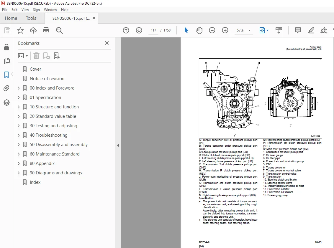
Overall drawing of power train unit 116
Power train hydraulic equipment arrangement drawing 118
Damper and universal joint 120
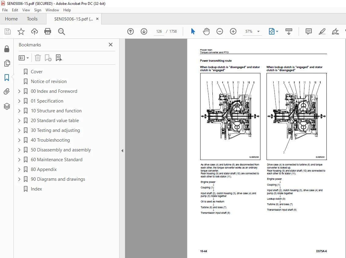
Torque converter and PTO 122
Torque converter control valve 128
Main relief valve and torque converter relief valve 130
Lockup clutch ECMV and stator clutch ECMV 132
Scavenging pump 137
Transmission control 138
PCCS lever 140
Transmission 144
Transmission ECMV 158
Transmission lubricating oil relief valve 163
Steering and brake control 164
Transfer unit, bevel gear shaft and steering 166
Steering control valve 172
Steering clutch ECMV and Steering brake ECMV 174
Parking brake valve 181
Sudden stop prevention valve 183
Final drive 185
Undercarriage and frame 190
Track frame 190
Idler cushion 192
Track roller bogie 193
Main frame 194
Suspension 196
Hydraulic system 199
Work equipment hydraulic piping diagram 199
PPC control piping diagram 203
Work equipment control 204
Hydraulic tank 206
Accumulator 208
PPC lock valve 209
PPC valve 211
Piston valve 222
Quick drop valve 223
Pin puller switch 224
Pin puller solenoid valve 225
Blade control lever (only for the machine with dual tilt specification) 227
Work equipment pump 228
Control valve 240
Self-pressure reducing valve 265
Work equipment 272
Cylinder stay 272
Cab 273
Cab mount 273
Cab 274
Electrical system 276
Engine control 276
Engine control system 277
CRI engine control system 286
Monitor system 288
Machine monitor 290
Lamp system 309
Engine preheat (electrical intake air heater) control 310
Palm command control system 311
Sensor 314
Vehicle health monitoring system (VHMS) 320
ORBCOMM system 326
Pre-lubrication system 329
20 Standard value table 333
Standard service value table 335
Standard value table for engine 335
Standard value table for machine 336
30 Testing and adjusting 345
Tools for testing, adjusting and troubleshooting 348
Diagnosis equipment list 348
Engine and cooling system 350
Testing engine speed 350
Testing intake air pressure (boost pressure) 354
Testing exhaust temperature 356
Testing exhaust gas color 360
Adjusting valve clearance 362
Measuring compression pressure 364
Testing blow-by pressure 367
Testing engine oil pressure 369
Testing EGR valve drive oil pressure 370
Handling of fuel system devices 372
Releasing residual pressure from fuel system 373
Testing fuel pressure 374
Handling of reduced cylinder mode operation 375
Handling of no injection cranking operation 375
Testing leakage from pressure limiter and return rate from injector 376
Bleeding air from fuel circuit 379
Testing fuel circuit for leakage 381
Replacing and adjusting alternator and air conditioner compressor belt 382
Measuring fan speed 383
Testing fan circuit oil pressure 384
Bleeding air from fan pump 385
Adjusting fuel control dial and decelerator pedal 386
Power train 388
Testing power train oil pressure 388
Adjusting transmission output speed sensor 406
Simple test procedure for brake performance 407
Adjusting brake pedal and parking brake lever 408
Adjusting position of pccs lever console 411
Emergency escape method when there is failure in power train 412
Undercarriage and frame 414
Inspecting wear of sprocket 414
Testing and adjusting track shoe tension 415
Hydraulic system 416
Measuring and adjusting work equipment oil pressure 416
Testing control circuit main pressure 419
Testing PPC valve output pressure 420
Adjusting play of PPC valve 422
Testing output pressure of ripper pin-puller solenoid valve 423
Checking location of cause of hydraulic drift of blade and ripper 424
Testing leakage inside work equipment cylinder 425
Releasing remaining pressure in work equipment cylinders 426
Bleeding air from work equipment cylinders 426
Adjusting ripper lever position 427
Work equipment 428
Adjusting work equipment lock lever 428
Adjusting blade 429
Cab and its attachments 431
Testing and adjusting operator’s cab 431
Testing and adjusting operator’s seat isolator 356
Electrical system 440
Special functions of machine monitor (EMMS) 440
Handling of voltage circuit of engine controller 501
Adjustment method when controller has been replaced 502
Preparation work for troubleshooting of electrical system 506
Inspection procedure of diode 510
Handling of optional devices 511
Request for opening ORBCOMM terminal 512
Initialization procedures for VHMS controller 514
Using method of KOMTRAX functions of ORBCOMM terminal 530
Precautions for replacing VHMS controller 533
Pm Clinic service 539
Pm Clinic service 539
40 Troubleshooting 551
General Information on troubleshooting 559
Points to remember when troubleshooting 559
Sequence of events in troubleshooting 560
Checks before troubleshooting 561
Classification and procedures for troubleshooting 586
Failure codes table 589
Phenomena and troubleshooting numbers 595
Information in troubleshooting table 597
Troubleshooting method for disconnecting wiring harness of pressure sensor system 599
Connection table for connector pin numbers 602
Connectors table and arrangement drawing 638
T-branch box and T-branch adapter table 652
Fuse locations table 655
Troubleshooting by failure code 659
Failure code [1380MW] Lock up clutch: Slip 659
Failure code [1500L0] Transmission clutch: Abnormal 660
Failure code [15E0MW] Transmission clutch: Slip 661
Failure code [15SAL1] Forward clutch: Fill high 662
Failure code [15SALH] Forward clutch: Fill Low 664
Failure code [15SBL1] Reverse clutch: Fill high 666
Failure code [15SBLH] Reverse clutch: Fill Low 668
Failure code [15SEL1] Speed 1st clutch: Fill high 670
Failure code [15SELH] Speed 1st clutch: Fill Low 672
Failure code [15SFL1] Speed 2nd clutch: Fill high 674
Failure code [15SFLH] Speed 2nd clutch: Fill Low 676
Failure code [15SGL1] Speed 3rd clutch: Fill high 678
Failure code [15SGLH] Speed 3rd clutch: Fill Low 680
Failure code [15SJL1] L/U: Fill high 682
Failure code [15SJLH] L/U: Fill low 684
Failure code [1800MW] P/T clutch: Slip 686
Failure code [2201L1] Right clutch: Fill high 688
Failure code [2201LH] Right clutch: Fill low 690
Failure code [2202L1] Left clutch: Fill high 692
Failure code [2202LH] Left clutch: Fill low 694
Failure code [2300NR] Brake Themal Load Abnormality 696
Failure code [2301L1] Right brake: Fill high 698
Failure code [2301LH] Right brake: Fill low 700
Failure code [2301NR] Steering Brake RH Themal Load Abnormality 702
Failure code [2302L1] Left brake: Fill high 704
Failure code [2302LH] Left brake: Fill low 706
Failure code [2302NR] Steering Brake LH Themal Load Abnormality 708
Failure code [7RFAKA] ECM ACC CUT RELAY: Disconnection 710
Failure code [7RFAKB] ECM ACC CUT RELAY: Short circuit 712
Failure code [AA10NX] Air Cleaner Clogging 714
Failure code [AB00MA] Battery Charge Abnormal 716
Failure code [B@BAZG] Eng Oil Press Low 716
Failure code [B@BAZK] Eng Oil Level Low 717
Failure code [B@BCNS] Eng Water Overheat 718
Failure code [B@BCZK] Eng Water Level Low 719
Failure code [B@CENS] T/C Oil Overheat 720
Failure code [B@HANS] Hyd Oil Overheat 721
Failure code [B@HAZK] Hyd Oil Level Low 722
Failure code [CA111] ECM Critical Internal Failure 724
Failure code [CA115] Eng Ne and Bkup Speed Sens Error 726
Failure code [CA122] Chg Air Press Sensor High Error 728
Failure code [CA123] Chg Air Press Sensor Low Error 730
Failure code [CA131] Throttle Sensor High Error 732
Failure code [CA132] Throttle Sensor Low Error 734
Failure code [CA135] Eng Oil Press Sensor High Error 736
Failure code [CA141] Eng Oil Press Sensor Low Error 738
Failure code [CA144] Coolant Temp Sens High Error 740
Failure code [CA145] Coolant Temp Sens Low Error 742
Failure code [CA153] Chg Air Temp Sensor High Error 744
Failure code [CA154] Chg Air Temp Sensor Low Error 746
Failure code [CA187] Sens Supply 2 Volt Low Error 748
Failure code [CA212] Eng Oil Temp Sensor High Error 750
Failure code [CA213] Eng Oil Temp Sensor Low Error 752
Failure code [CA221] Ambient Press Sens High Error 754
Failure code [CA222] Ambient Press Sens Low Error 756
Failure code [CA227] Sens Supply 2 Volt High Error 758
Failure code [CA234] Eng Overspeed 759
Failure code [CA238] Ne Speed Sens Supply Volt Error 760
Failure code [CA263] Fuel Temp Sensor High Error 762
Failure code [CA265] Fuel Temp Sensor Low Error 764
Failure code [CA271] IMV/PCV1 Short Error 766
Failure code [CA272] IMV/PCV1 Open Error 767
Failure code [CA273] PCV2 Short Error 768
Failure code [CA274] PCV2 Open Error 769
Failure code [CA322] Inj #1 (L#1) Open/Short Error 770
Failure code [CA323] Inj #5 (L#5) Open/Short Error 772
Failure code [CA324] Inj #3 (L#3) Open/Short Error 774
Failure code [CA325] Inj #6 (L#6) Open/Short Error 776
Failure code [CA331] Inj #2 (L#2) Open/Short Error 778
Failure code [CA332] Inj #4 (L#4) Open/Short Error 780
Failure code [CA342] Calibration Code Incompatibility 782
Failure code [CA351] Injectors Drive Circuit Error 783
Failure code [CA352] Sens Supply 1 Volt Low Error 784
Failure code [CA386] Sens Supply 1 Volt High Error 786
Failure code [CA441] Battery Voltage Low Error 787
Failure code [CA442] Battery Voltage High Error 788
Failure code [CA449] Rail Press Very High Error 789
Failure code [CA451] Rail Press Sensor High Error 790
Failure code [CA452] Rail Press Sensor Low Error 792
Failure code [CA553] Rail Press High Error 794
Failure code [CA554] Rail Press Sensor In Range Error 795
Failure code [CA559] Rail Press Low Error 796
Failure code [CA689] Eng Ne Speed Sensor Error 800
Failure code [CA731] Eng Bkup Speed Sens Phase Error 802
Failure code [CA757] All Continuous Data Lost Error 803
Failure code [CA778] Eng Bkup Speed Sensor Error 804
Failure code [CA1228] EGR Valve Servo Error 1 806
Failure code [CA1625] EGR Valve Servo Error 2 807
Failure code [CA1633] KOMNET Datalink Timeout Error 808
Failure code [CA2185] Throt Sens Sup Volt High Error 809
Failure code [CA2186] Throt Sens Sup Volt Low Error 810
Failure code [CA2249] Rail Press Very Low Error 811
Failure code [CA2271] EGR Valve Pos Sens High Error 812
Failure code [CA2272] EGR Valve Pos Sens Low Error 814
Failure code [CA2351] EGR Valve Sol Current High Error 816
Failure code [CA2352] EGR Valve Sol Current Low Error 818
Failure code [D110KB] Battery Relay: Drive Short Circuit 820
Failure code [D130KA] Neutral relay: Disconnection 822
Failure code [D130KB] Neutral relay: Short circuit 824
Failure code [D161KA] Back-up alarm releay: Disconnection 826
Failure code [D161KB] Back-up alarm releay: Short circuit 828
Failure code [D182KZ] Preheater Relay Abnormality 830
Failure code [D190KA] ACC signal relay: Disconnection 832
Failure code [D190KB] ACC signal relay: Short circuit 834
Failure code [D1EFKA] Pre lub motor relay: Disconnection 836
Failure code [D1EFKB] Pre lub motor relay: Short circuit 838
Failure code [DAFRKR] Monitor: Can communication lost (PT) 840
Failure code [dAFRKR] Monitor: CAN communication lost (WE) 841
Failure code [DAFRMC] CAN Discon (Monitor Detected) 842
Failure code [DB2RKR] ENG cont: Can communication lost (PT) 847
Failure code [dB2RKR] ENG controller: CAN communication lost (WE) 850
Failure code [DB90KT] WE controller: Abnormality in controller 851
Failure code [DB91KK] WE controller: Source voltage reduction 852
Failure code [DB92KK] WE controller: Output voltage reduction 854
Failure code [DB97KK] WE cont: Sensor voltage 5 V (2) reduction 856
Failure code [DB99KQ] WE controller: Type select signal 858
Failure code [DB9RKR] WE controller: Can communication lost (PT) 859
Failure code [DBB0KK] VHMS controller:Source voltage reduction 862
Failure code [DBB0KQ] VHMS connector connection abnormality 864
Failure code [DBB3KK] VHMS controller: Source voltage reduction 866
Failure code [DBB5KP] VHMS: Output sensor1 voltage reduction 868
Failure code [DBB6KP] VHMS:Output sensor2 voltage reduction 870
Failure code [DBB7KP] VHMS:Output sensor3 voltage reduction 872
Failure code [DBBQKR] PT cont: Can communication lost (VHMS) 873
Failure code [DBE0KT] PT controller: Abnormality in controller 873
Failure code [DBE1KK] PT controller: Source voltage reduction 874
Failure code [DBE2KK] PT controller: Output voltage reduction 876
Failure code [DBE5KK] PT cont: Sensor voltage 5 V (1) reduction 878
Failure code [DBE6KK] PT cont: Sensor voltage 24 V reduction 880
Failure code [DBE7KK] PT cont: Sensor voltage 5 V (2) reduction 882
Failure code [DBE9KQ] PT controller: Type select signal 884
Failure code [DBERKR] PT controller: Can communication lost (WE) 885
Failure code [DD12KA] Shift up Sw: Disconnection 888
Failure code [DD12KB] Shift up Sw: Short circuit 890
Failure code [DD13KA] Shift down Sw: Disconnection 892
Failure code [DD13KB] Shift down Sw: Short circuit 894
Failure code [DD14KA] Parking lever Sw: Dissconnection 896
Failure code [DD14KB] Parking lever Sw: Short circuit 898
Failure code [DDB9L4] Reverse SW Signal disagreement 900
Failure code [DDE2KA] Pre lub oil press sw: Disconnection 902
Failure code [DDK3L4] Forward SW Signal disagreement 904
Failure code [DDK5KA] Shift switch disconnection 906
Failure code [DDK5KB] Shift switch short circuit 908
Failure code [DDN2LD] Blade tilt RH pressure SW abnormality 910
Failure code [DDN3LD] Blade tilt LH pressure SW abnormality 912
Failure code [DDN7KA] WEQ Knob Sw (down): Disconnection 914
Failure code [DDN7KB] WEQ Knob Sw (down): Short circuit 916
Failure code [DDN9KA] WEQ Knob Sw (up): Disconnection 918
Failure code [DDN9KB] WEQ Knob Sw (up): Short circuit 920
Failure code [DDNALD] Blade lift up pressure SW abnormality 922
Failure code [DDNBLD] Ripper lift up pressure SW abnormality 924
Failure code [DDNCLD] Ripper lift down pressure SW abnormality 926
Failure code [DDNDLD] Ripper tilt in pressure SW abnormality 928
Failure code [DDNELD] Ripper tilt back pressure SW abnormality 930
Failure code [DDNFLD] Blade lift down pressure SW abnormality 932
Failure code [DDNLKA] Weq lock Sw: Disconnection 934
Failure code [DDNLKB] Weq lock Sw: Short circuit 936
Failure code [DDT5KA] Neutral switch disconnection 938
Failure code [DDT5KB] Neutral switch short circuit 940
Failure code [DDT5KQ] Lever SPEC selection signal disagreement 942
Failure code [DDTSL1] S/C: Fill high 944
Failure code [DDTSLH] S/C: Fill low 946
Failure code [DGE5KX] Ambient temp sensor abnormality 948
Failure code [DGS1KX] Hyd oil temp: signal abnormal 950
Failure code [DGT1KA] T/C oil temp sensor: Abnormal 952
Failure code [DGT1KX] T/C oil temp sensor: Abnormal 954
Failure code [DGT5KA] F exhaust temp sensor disconnection 956
Failure code [DGT5KB] F exhaust temp sensor short circuit 958
Failure code [DGT6KA] R exhaust temp sensor disconnection 960
Failure code [DGT6KB] R exhaust temp sensor short circuit 962
Failure code [DH21KA] Weq pressure sensor: Disconnection 964
Failure code [DH21KB] Weq pressure sensor: Short circuit 966
Failure code [DHE5KB] ENG blow-by pressure sensor disconnection 968
Failure code [DHE5KY] ENG blow-by pressure sensor short circuit 970
Failure code [DHT3KX] T/M oil pressure sensor abnormality 972
Failure code [DHT5KA] T/C in-pressure sensor: Disconnection 974
Failure code [DHT5KB] T/C in-pressure sensor: Short circuit 976
Failure code [DHT7KA] T/C out-pressure sensor: Disconnection 978
Failure code [DHT7KB] T/C out-pressure sensor: Short circuit 980
Failure code [DK10KA] Fuel control Dial: Disconnection 982
Failure code [DK10KB] Fuel control Dial: Short circuit 984
Failure code [DK30KA] ST lever 1: Disconnection 986
Failure code [DK30KB] ST lever 1: Short circuit 988
Failure code [DK30KX] ST lever: Out of normal range 990
Failure code [DK30KZ] ST lever: Disconnection or short circuit 990
Failure code [DK30L8] ST lever: Signal mismatch 991
Failure code [DK31KA] ST lever 2: Disconnection 992
Failure code [DK31KB] ST lever 2: Short circuit 994
Failure code [DK40KA] Brake potentiometer: Disconnection 996
Failure code [DK40KB] Brake potentiometer: Short circuit 998
Failure code [DK55KX] FR lever: Out of normal range1000
Failure code [DK55KZ] FR lever: Disconnection or short circuit1000
Failure code [DK55L8] FR lever: Signal mismatch1001
Failure code [DK56KA] FR lever 1: Disconnection1002
Failure code [DK56KB] FR lever 1: Short circuit1004
Failure code [DK57KA] FR lever 2: Disconnection1006
Failure code [DK57KB] FR lever 2: Short circuit1008
Failure code [DK60KA] Acceleration sensor: Disconnection1010
Failure code [DK60KB] Acceleration sensor: Short circuit1012
Failure code [DKH1KA] Pitch angle sensor: Disconnection1014
Failure code [DKH1KB] Pitch angle sensor: Short circuit1016
Failure code [DLF1KA] T/C out-speed sensor: Disconnection1018
Failure code [DLM3KA] Fan rev sensor: Disconnection1019
Failure code [DLM3MB] Fan control: Decline1020
Failure code [DLT3KA] T/M out-speed sensor: Disconnection1021
Failure code [DLT3KB] T/M out-speed sensor: Abnormal1022
Failure code [DW59KA] Blade dual selector SOL disconnection1023
Failure code [DW59KB] Blade dual selector SOL short circuit1024
Failure code [DW59KY] Blade dual selector SOL hot short1025
Failure code [DW5AKA] Blade pitch selector SOL disconnection1026
Failure code [DW5AKB] Blade pitch selector SOL short circuit1027
Failure code [DW5AKY] Blade pitch selector SOL Short circuit1028
Failure code [DW7BKA] Fan rev EPC: Disconnection1029
Failure code [DW7BKB] Fan rev EPC: Short circuit1030
Failure code [DWN3KA] Ssp solenoid: Disconnection1031
Failure code [DWN3KB] Ssp solenoid: Short circuit1032
Failure code [DWN3KY] SSP solenoid: Short circuit1034
Failure code [DWN5KA] Fan pump solenoid 1: Disconnection1036
Failure code [DWN5KB] Fan pump solenoid 1: Short circuit1037
Failure code [DWN5KY] Fan pump solenoid 1: Short circuit1038
Failure code [DWNCKA] Fan pump solenoid 2: Disconnection1040
Failure code [DWNCKB] Fan pump solenoid 2: Short circuit1041
Failure code [DWNCKY] Fan pump solenoid 2: Short circuit1042
Failure code [DXH1KA] Lock-up ECMV: Disconnection1044
Failure code [DXH1KB] Lock-up ECMV: Short circuit1045
Failure code [DXH1KY] Lock-up ECMV: Short circuit1046
Failure code [DXH4KA] 1st clutch ECMV: Disconnection1048
Failure code [DXH4KB] 1st clutch ECMV: Short circuit1049
Failure code [DXH4KY] 1st clutch ECMV: Short circuit1050
Failure code [DXH5KA] 2nd clutch ECMV: Disconnection1052
Failure code [DXH5KB] 2nd clutch ECMV: Short circuit1053
Failure code [DXH5KY] 2nd clutch ECMV: Short circuit1054
Failure code [DXH6KA] 3rd clutch ECMV: Disconnection1056
Failure code [DXH6KB] 3rd clutch ECMV: Short circuit1057
Failure code [DXH6KY] 3rd clutch ECMV: Short circuit1058
Failure code [DXH7KA] R clutch ECMV: Disconnection1060
Failure code [DXH7KB] R clutch ECMV: Short circuit1061
Failure code [DXH7KY] R clutch ECMV: Short circuit1062
Failure code [DXH8KA] F clutch ECMV: Disconnection1064
Failure code [DXH8KB] F clutch ECMV: Short circuit1065
Failure code [DXH8KY] F clutch ECMV: Short circuit1066
Failure code [DXH9KA] Right clutch ECMV: Disconnection1068
Failure code [DXH9KB] Right clutch ECMV: Short circuit1069
Failure code [DXH9KY] Right clutch ECMV: Short circuit1070
Failure code [DXHAKA] Left clutch ECMV: Disconnection1072
Failure code [DXHAKB] Left clutch ECMV: Short circuit1073
Failure code [DXHAKY] Left clutch ECMV: Short circuit1074
Failure code [DXHBKA] Right brake ECMV: Disconnection1076
Failure code [DXHBKB] Right brake ECMV: Short circuit1077
Failure code [DXHBKY] Right brake ECMV: Short circuit1078
Failure code [DXHCKA] Left brake ECMV: Disconnection1080
Failure code [DXHCKB] Left brake ECMV: Short circuit1081
Failure code [DXHCKY] Left brake ECMV: Short circuit1082
Failure code [DXJBKA] S/C ECMV: Disconnection1084
Failure code [DXJBKB] S/C ECMV: Short circuit1085
Failure code [DXJBKY] S/C ECMV: Short circuit1086
Failure code [DY2HKA] Pre lub motor: Disconnection1088
Failure code [F@BBZL] ENG blow-by pressure high level1090
Failure code [F@BYNR] F exhaust temp high level (2)1091
Failure code [F@BYNS] F exhaust temp high level (1)1092
Failure code [F@BZNR] R exhaust temp high level (2)1093
Failure code [F@BZNS] R exhaust temp high level (1)1094
Troubleshooting of electrical system (E-mode)1095
Information contained in troubleshooting table1095
E-1 Engine does not start (starting motor does not turn)1097
E-2 Preheater does not operate1100
E-3 When starting switch is turned ON, machine monitor displays nothing1104
E-4 When starting switch is turned ON (before starting engine), basic check item lights up1106
E-5 Precaution item lights up while engine is running1108
E-6 Emergency stop item lights up while engine is running1110
E-7 Engine coolant temperature gauge does not indicate normally1111
E-8 Fuel gauge does not indicate properly1112
E-9 Power train oil temperature gauge (multi-gauge) does not indicate normally1114
E-10 Hydraulic temperature gauge (multi-gauge) does not indicate normally1115
E-11 Contents of display by machine monitor are different from applicable machine1116
E-12 Machine monitor does not display some items1116
E-13 Function switch does not work1116
E-14 Operation mode does not change1117
E-15 Gearshift mode does not change1117
E-16 Customize function does not operate normally1118
E-17 Customize memory function does not operate normally1118
E-18 Alarm buzzer does not sound or does not stop1119
E-19 When starting switch is turned OFF, service meter is not displayed1119
E-20 Machine monitor cannot be set in service mode1119
E-21 The ripper pin puller cylinder does not operate1120
E-22 Horn does not sound or does not stop1122
E-23 Back-up alarm does not sound or does not stop1124
E-24 Fan does not reverse1126
E-25 The head lamp and rear lamp do not light up1127
E-26 Windshield wiper does not operate1134
E-27 Window washer does not operate1140
E-28 Electric priming pump does not operate or does not stop automatically1146
E-29 Orbcomm terminal does not operate normally (Data are not transmitted)1148
E-30 Gear cannot be shifted1150
Troubleshooting of hydraulic and mechanical system (H-mode)1151
Information in troubleshooting table1151
List of Failure Modes and Causes1152
H-1 Machine lacks power(or drawbar pull)1154
H-2 Machine cannot travel (at 2nd or 3rd each speed)1156
H-3 Machine cannot travel at any gear speeds1157
H-4 Machine travels only in one direction, forward or reverse1158
H-5 Large time lag at gear shifting or directional change1159
H-6 Machine connot turn1160
H-7 Machine turns only to one side1161
H-8 Machine overruns at turnning1162
H-9 Brake does not work1162
H-10 Torque converter does not lock up1163
H-11 Power train oil overheats1164
H-12 All work equipment operates too slow or lacks power1165
H-13 All work equipment does not operate1166
H-14 Blade lift cylinder speed is too slow or lacks power1167
H-15 Blade tilt cylinder speed is too slow or lacks power1167
H-16 Ripper lift cylinder speed is too slow or lacks power1168
H-17 Ripper tilt cylinder speed is too slow or lacks power1168
H-18 Excessive hydraulic drift of blade lift cylinder1169
H-19 Excessive hydraulic drift of blade tilt cylinder1169
H-20 Excessive hydraulic drift of ripper lift cylinder1170
H-21 Ripper pin puller cylinder does not operate (machine with giant ripper)1170
H-22 Blade pitch does not work (machine with dual tilt specification)1171
H-23 Abnormal noise from around work equipment pump1171
H-24 Abnormal fan rotation (noise and/or vibration are abnormally large or engine overheats)1172
H-25 Operator’s seat isolator quakes abnormally or makes shocks (Machine with operator’s seat isolator)1172
Troubleshooting of engine (S-mode)1174
Method of using troubleshooting chart1174
S-1 Engine does not start easily1178
S-2 Engine does not start1180
S-3 Engine does not rev up smoothly (response-up is poor)1184
S-4 Engine stops during operation1186
S-5 Engine does not rotate smoothly (hunting)1187
S-6 Engine lacks power (or output shortage)1188
S-7 Exhaust smoke is black (Incomplete combustion)1190
S-8 Oil is consumption is excessive(or exhaust smoke is blue)1192
S-9 Engine oil becomes contaminated quickly1193
S-10 Fuel consumption is excessive1194
S-11 Oil mixes into coolant(coolant blows back or is reduced)1195
S-12 Engine pressure monitor lights up (drop in engine oil pressure)1196
S-13 Oil level rises (Coolant or fuel mixes into oil)1197
S-14 Coolant temperature rises too high (overheating)1199
S-15 Abnormal noise is heard1200
S-16 Vibration is excessive1201
S-17 Air cannot be bled from fuel circuit (when air bleeding is performed after filter is replaced or fuel is used up and then air is bled, engine does not start or it starts but stalls)1202
50 Disassembly and assembly1205
General information on disassembly and assembly1208
How to read this manual1208
Coating materials list1210
Special tools list1213
Sketches of special tools1220
Engine and cooling system1228
Removal and installation of fuel supply pump assembly1228
Removal and installation of fuel injector assembly1232
Removal and installation of cylinder head assembly1237
Removal and installation of radiator guard assembly1253
Removal and installation of cooling assembly (radiator, after cooler, and hydraulic oil cooler)1258
Removal and installation of radiator1263
Removal and installation of hydraulic oil cooler1265
Removal and installation of aftercooler1266
Removal and installation of engine assembly1267
Removal and installation of engine hood assembly1274
Removal and installation of engine front seal1277
Removal and installation of engine rear seal1279
Removal and installation of fan drive assembly1283
Removal and installation of fan motor assembly1285
Removal and installation of fuel tank assembly1287
Power train1290
Removal and installation of damper assembly1290
Disassembly and assembly of damper assembly1294
Removal and installation of power train unit assembly1297
Disconnection and connection of power train unit assembly1304
Disassembly and assembly of PTO assembly1313
Disassembly and assembly of torque converter assembly1319
Disassembly and assembly of TORQFLOW transmission assembly1329
Disassembly and assembly of steering case assembly1357
Removal and installation of power train pump and lubrication pump assembly1373
Removal and installation of scavenging pump assembly1374
Removal and installation of final drive assembly1375
Disassembly and assembly of final drive assembly1377
Undercarriage and frame1390
Removal and installation of track frame assembly1390
Removal and installation of idler assembly1395
Disassembly and assembly of idler assembly1396
Removal and installation of recoil spring assembly1400
Disassembly and assembly of recoil spring assembly1405
Removal and installation of track roller assembly1407
Disassembly and assembly of track roller assembly1410
Removal and installation of carrier roller assembly1413
Disassembly and assembly of carrier roller assembly1414
Removal and installation of bogie assembly1418
Disassembly and assembly of bogie assembly1423
Removal and installation of first bogie assembly1425
Separation and connection of track shoe assembly1430
Overall disassembly and assembly of track shoe1434
Link press press-fitting jig dimensions1451
Disassembly and assembly of one link assembly in the field1452
Disassembly and assembly of master link1457
Removal and installation of pivot shaft assembly1461
Removal and installation of equalizer bar1462
Disassembly and assembly of equalizer bar bushing1466
Removal and installation of segment tooth1468
Hydraulic system1470
Removal and installation of hydraulic tank assembly1470
Removal and installation of work equipment pump assembly1473
Removal and installation of fan pump assembly1477
Removal and installation of control valve assembly1479
Disassembly and assembly of control valve assembly1481
Disassembly and assembly of blade PPC valve assembly1486
Disassembly and assembly of ripper PPC valve assembly1489
Disassembly and assembly of hydraulic cylinder assembly1491
Disassembly and assembly of ripper pin puller cylinder assembly1499
Work equipment1502
Removal and installation of blade assembly1502
Disassembly and assembly of blade assembly1504
Disassembly and assembly of giant ripper assembly1508
Cab and its attachments1512
Removal and installation of ROPS guard1512
Removal and installation of operator’s cab assembly1513
Removal and installation of floor frame assembly1517
Removal and installation of air conditioner unit assembly1522
Removal and installation of operator’s seat isolator1206
Disassembly and assembly of operator’s seat isolator1208
Electrical system1532
Removal and installation of transmission controller assembly and steering controller assembly1532
Removal and installation of engine controller assembly1533
Removal and installation of VHMS controller assembly1535
Removal and installation of machine monitor assembly1536
60 Maintenance Standard1539
Engine and cooling system1541
Engine mount1541
Cooling fan pump1543
Cooling fan motor1550
Power train1552
Power train unit1552
Damper and universal joint1554
Torque converter and PTO1557
Main relief valve and torque converter relief valve1560
Lockup clutch ECMV and stator clutch ECMV1561
Scavenging pump1562
Transmission control1563
Transmission1564
Transmission lubricating oil relief valve1568
Power train and lubrication pump1569
Transfer, bevel gear shaft and steering unit1570
Steering control valve1576
Steering clutch ECMV and steering brake ECMV1577
Parking brake valve1578
Final drive1579
Sprocket1582
Undercarriage and frame1584
Track frame1584
Idler cushion1586
Idler1588
Track roller1590
Carrier roller1592
Track roller bogie1593
Track shoe1594
Main frame1598
Suspension1600
Hydraulic system1605
PPC valve1605
Hydraulic cylinder1610
Quick drop valve1613
Work equipment pump1614
Control valve1617
Self-pressure reducing valve1629
Work equipment1631
Cylinder stay1631
Blade1632
Cutting edge and end bit1636
Ripper1638
80 Appendix1641
Air Conditioner1643
Caution about refrigerant1643
Air conditioner component1644
Configuration and function of refrigeration cycle1646
Outline of refrigeration cycle1647
Air conditioner unit1650
Blower unit1654
FRESH/RECIRC air changeover damper1655
Compressor1656
Condenser1657
Receiver drier1658
Air conditioner control panel1660
Procedure for testing and troubleshooting1662
Circuit diagram and arrangement of connector pins1664
System diagram1666
Part and connector locations1668
Testing temperature control1672
Testing FRESH/RECIC air changeover1672
Testing relay1674
Troubleshooting chart 11676
Troubleshooting chart 21678
Information in troubleshooting table1680
Troubleshooting for power supply system (Air conditioner does not operate)1682
Troubleshooting for compressor system (Air is not cooled)1684
Troubleshooting for blower motor system (Air does not come out or air flow is abnormal)1688
Troubleshooting for temperature control1694
Troubleshooting for FRESH/RECIRC air changeover1696
Troubleshooting with gauge pressure1698
Connection of service tool1700
Precautions for disconnecting and connecting1702
Handling of compressor oil1704
90 Diagrams and drawings1707
Hydraulic diagrams and drawings1709
Symbols used in hydraulic circuit diagrams1709
Power train hydraulic circuit diagram1711
Hydraulic circuit diagram1713
Electrical diagrams and drawings1717
Symbols used in electrical circuit diagrams1717
Electrical circuit diagram1721
Index1749
S.M 29/12/24