Komatsu Bulldozer D275AX-5E0 Shop Manual SEN00919-24 – PDF DOWNLOAD
$36.95
Komatsu Bulldozer D275AX-5E0 Shop Manual SEN00919-24 – PDF DOWNLOAD
SERIAL NUMBERS 30001 and up
Description
Komatsu Bulldozer D275AX-5E0 Shop Manual SEN00919-24 – PDF DOWNLOAD
FILE DETAILS:
Komatsu Bulldozer D275AX-5E0 Shop Manual SEN00919-24 – PDF DOWNLOAD
Language : English
Pages :1646
Downloadable : Yes
File Type : PDF
IMAGES PREVIEW OF THE MANUAL:
DESCRIPTION:
Komatsu Bulldozer D275AX-5E0 Shop Manual SEN00919-24 – PDF DOWNLOAD
SERIAL NUMBERS 30001 and up
TABLE OF CONTENTS:
Komatsu Bulldozer D275AX-5E0 Shop Manual SEN00919-24 – PDF DOWNLOAD
SERIAL NUMBERS 30001 and up
Cover 1
00 Index and foreword 3
Index 3
Composition of shop manual 4
Table of contents 6
Foreword and general information 19
Safety notice 20
How to read the shop manual 25
Explanation of terms for maintenance standard 27
Handling of electric equipment and hydraulic component 29
Handling of connectors newly used for engines 38
How to read electric wire code 41
Precautions when carrying out operation 44
Method of disassembling and connecting push-pull type coupler 47
Standard tightening torque table 50
Conversion table 54
01 Specification 61
Specification and technical data 61
Specefication dimension drawings 62
Specifications 64
Weight table 76
Table of fuel, coolant and lubricants 80
10 Structure, function and maintenance standard 83
Engine and cooling system 83
Engine mount 84
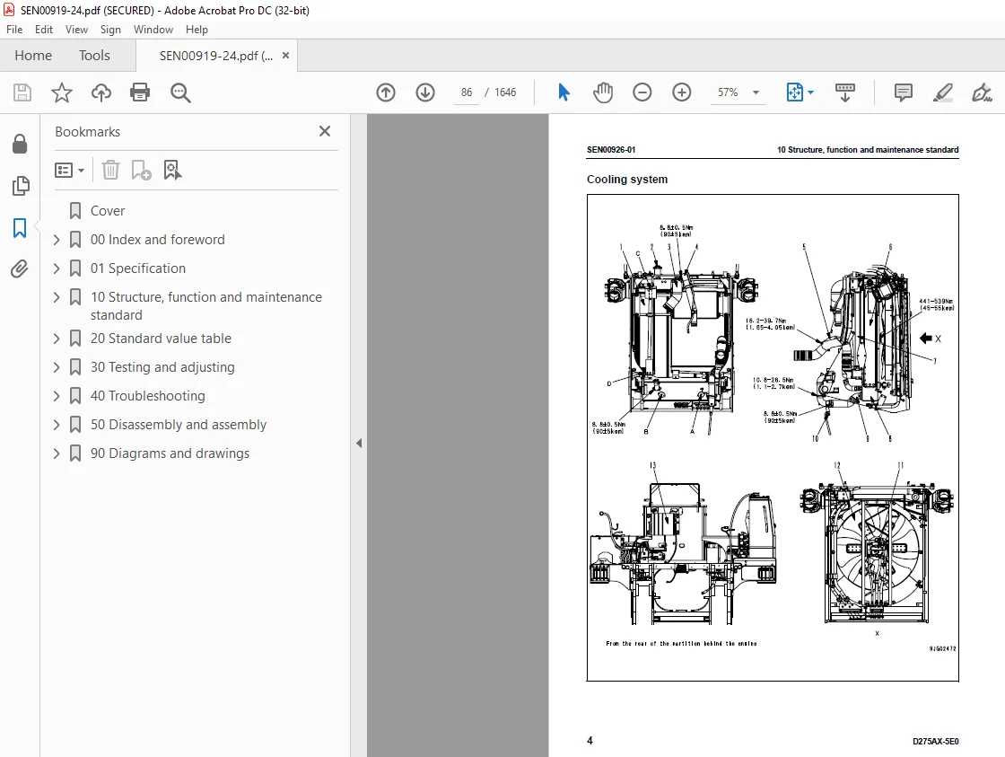
Cooling system 86
Cooling fan pump 88
Cooling fan motor 96
Power train, Part 1 103
Power train skeleton 104
HSS system 106
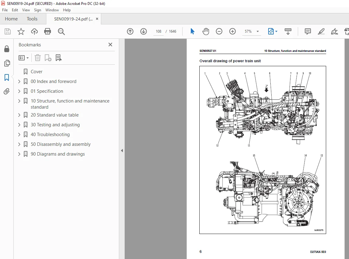
Overall drawing of power train unit 108
Power train hydraulic piping drawing 110
Transmission control 111
Steering, brake control 112
Damper, universal joint 114
Torque converter, PTO 116
Transmission 130
Tranmission ECMV 142
Main relief valve and torque convertor relif valve 148
Torque converter valve 152
Lubrication relief valve 160
Power train system, Part 2 163
Bevel gear shaft, HSS, brake 165
Brake valve 178
Brake ECMV 179
Parking brake valve 185
Sudden brake prevention valve 186
Final drive 187
Sprocket 192
Undercarriage and frame 195
Track frame 196
Idler cushion 200
Idler 204
Track roller 206
Track roller bogie 208
Carrier roller 210
Track shoe 212
Main frame 216
Suspension 218
Hydraulic system, Part 1 227
Work equipment hydraulic piping diagram 228
PPC control piping diagram 232
Work equipment control 234
Hydraulic tank 236
Scavenging pump 240
Work equipment pump 242
Power train pump, steering lubrication pump 258
HSS pump 259
HSS motor 275
PPC, HSS charge filter 284
Hydraulic system, Part 2 287
Control valve 288
Self pressure reducing valve 317
Hydraulic system, Part 3 325
HSS charge filter bypass 326
HSS oil cooler bypass valve 328
PPC valve 330
PCCS lever 342
PPC lock valve 345
Hydraulic cylinder 346
Piston valve 352
Quick drop valve 353
Pin puller switch 354
Pin puller solenoid valve 355
Blade control knob 357
Pitch, dual tilt solenoid valve 358
Accumulator 359
Work equipment 361
Cylinder stay 362
Blade 364
Ripper 370
Cab and its attachments 375
Cab and its attachments 376
Cab mount 376
Cab 377
Air conditioner 379
Electrical system 381
Engine control system 382
CRI engine control system 392
Monitor system 394
Machine monitor 396
Mode selection system 410
Sensors 414
Electrical equipment 420
Palm command control system 422
KOMTRAX system 424
20 Standard value table 427
Standard service value table 427
Standard value table for engine 428
Standard value table for machine 429
30 Testing and adjusting 437
Testing and adjusting, Part 1 437
Tools for testing, adjusting, and troubleshooting 439
Testing engine speed 442
Testing intake air pressure (Boost pressure) 445
Testing exhaust temperature 447
Testing exhaust gas color 449
Adjusting valve clearance 451
Testing compression pressure 453
Testing blow-by pressure 455
Testing engine oil pressure 456
Testing EGR valve and bypass valve drive oil pressure 457
Handling of fuel system devices 458
Releasing residual pressure from fuel system 458
Testing fuel pressure 459
Testing fuel return rate and fuel leakage 460
Bleeding air from fuel circuit 464
Testing fuel circuit for leakage 466
Testing and adjusting alternator belt tension 467
Handling controller voltage circuit 468
Testing and adjusting air conditioner compressor belt 469
Testing fan speed 470
Testing fan circuit oil pressure 471
Bleeding air from fan pump 472
Adjusting fuel control dial and decelerator pedal 473
Testing and adjusting, Part 2 477
Testing power train oil pressure 479
Testing and adjusting HSS oil pressure 488
Adjusting transmission speed sensor 493
Bleeding air from HSS pump 494
Simple method of testing brake performance 494
Adjusting brake pedal and parking brake lever 495
Adjusting PCCS lever console position 498
Emergency escape method when power train has trouble 499
Adjusting clearance of idler 502
Inspecting wear of sprocket 503
Testing and adjusting track shoe tension 504
Testing and adjusting work equipment oil pressure 505
Testing control circuit main pressure 509
Testing PPC valve output pressure 510
Adjusting play of PPC valve 512
Testing outlet pressure of ripper pin puller solenoid valve 515
Testing parts which cause hydraulic drift of blade and ripper 516
Testing internal leakage of work equipment cylinder 517
Releasing residual pressure from work equipment cylinder 518
Bleeding air from work equipment cylinder 519
Adjusting ripper lever position 520
Adjusting work equipment lock lever 521
Adjusting blade 522
Testing and adjusting operator’s cab 526
Testing and adjusting, Part 3 529
Special functions of machine monitor (EMMS) 530
Testing and adjusting, Part 4 581
Adjustment method when controller has been replaced 582
Method of starting use of KOMTRAX terminal 584
Indication by KOMTRAX terminal lamps 587
Preparation work for troubleshooting for electric system 590
Handling of optional devices 593
Pm Clinic service 594
40 Troubleshooting 605
Failure code table and fuse locations 605
Failure codes table 606
Fuse locations 614
General information on troubleshooting 621
Points to remember when troubleshooting 622
Sequence of events in troubleshooting 623
Check before troubleshooting 624
Classification and procedures for troubleshooting 625
Contents of troubleshooting table 628
Connection table for connector pin numbers 630
T- branch box and T- branch adapter table 666
Troubleshooting by failure and error codes, Part 1 671
Failure code [1500L0] Transmission clutch dual engagement 673
Failure code [15SAL1] Forward clutch oil pressure 1 674
Failure code [15SALH] Forward clutch oil pressure 2 676
Failure code [15SBL1] Reverse clutch oil pressure 1 678
Failure code [15SBLH] Reverse clutch oil pressure 2 680
Failure code [15SEL1] 1st clutch oil pressure 1 682
Failure code [15SELH] 1st clutch oil pressure 2 683
Failure code [15SFL1] 2nd clutch oil pressure 1 684
Failure code [15SFLH] 2nd clutch oil pressure 2 685
Failure code [15SGL1] 3rd clutch oil pressure 1 686
Failure code [15SGLH] 3rd clutch oil pressure 2 687
Failure code [1800MW] Power train clutch slip 688
Failure code [2300NR] Brake thermal load 689
Failure code [2301L1] Right steering brake oil pressure 1 690
Failure code [2301LH] Right steering brake oil pressure 2 692
Failure code [2301NR] Right steering brake thermal load 694
Failure code [2302L1] Left steering brake oil pressure 1 696
Failure code [2302LH] Left steering brake oil pressure 2 698
Failure code [2302NR] Left steering brake thermal load 700
Failure code [6001ZK] Failure code for design 700
Failure code [A000NS] Engine overheat 701
Failure code [AA10NX] Air cleaner clogging 702
Failure code [AB00MA] Battery charge abnormal 704
Failure code [B@BAZG] Eng oil press low 706
Failure code [B@BAZK] Eng oil level low 707
Failure code [B@BCNS] Eng coolant overheat 708
Failure code [B@BCZK] Radiator coolant level low 708
Failure code [B@BEBF] Water gets mixed with fuel 709
Failure code [B@BFZK] Fuel level abnormal reduction 709
Failure code [B@CENS] Torque converter oil overheat 710
Failure code [B@CHZG] HSS charge oil pressure reduction 711
Failure code [B@CHZK] Power train oil oil level reduction 711
Failure code [B@GAZK] Battery electrolyte level reduction 712
Failure code [B@HANS] Hyd oil overheat 712
Failure code [B@HAZK] Hydraulic oil level reduction 713
Troubleshooting by failure and error codes, Part 2 715
Failure code [CA111] EMC critical internal failure 718
Failure code [CA115] Eng Ne and Bkup speed sens error 720
Failure code [CA122] Chg air press sensor high error 722
Failure code [CA123] Chg air press sensor low error 724
Failure code [CA131] Throttle sensor high error 726
Failure code [CA132] Throttle sensor low error 728
Failure code [CA135] Eng oil press sensor high error 730
Failure code [CA141] Eng oil press sensor low error 732
Failure code [CA144] Coolant temp sens high error 734
Failure code [CA145] Coolant temp sens low error 736
Failure code [CA153] Chg air temp sensor high error 738
Failure code [CA154] Chg air temp sensor low error 740
Failure code [CA187] Sens supply 2 volt low error 740
Failure code [CA221] Ambient press sens high error 742
Failure code [CA222] Ambient press sens low error 744
Failure code [CA227] Sens supply 2 volt high error 746
Failure code [CA234] Eng overspeed 748
Failure code [CA238] Ne speed sens supply volt error 750
Failure code [CA263] Fuel temp sensor high error 752
Failure code [CA265] Fuel temp sensor low error 754
Failure code [CA271] PCV1 short error 755
Failure code [CA272] PCV1 open error 756
Failure code [CA273] PCV2 short error 757
Failure code [CA274] PCV2 open error 758
Failure code [CA322] Inj #1 (L#1) open/short error 760
Failure code [CA323] Inj #5 (L#5) open/short error 762
Failure code [CA324] Inj #3 (L#3) open/short error 764
Failure code [CA325] Inj #6 (L#6) open/short error 766
Failure code [CA331] Inj #2 (L#2) open/short error 768
Failure code [CA332] Inj #4 (L#4) open/short error 770
Failure code [CA342] Calibration code incompatibility 772
Failure code [CA351] Injectors drive circuit error 774
Failure code [CA352] Sens supply 1 volt low error 776
Failure code [CA386] Sens supply 1 volt high error 778
Failure code [CA441] Battery voltage low error 780
Failure code [CA442] Battery voltage high error 780
Failure code [CA449] Rail press very high error 781
Failure code [CA451] Rail press sensor high error 782
Failure code [CA452] Rail press sensor low error 784
Failure code [CA553] Rail press high error 784
Failure code [CA554] Rail press sensor in range error 785
Failure code [CA559] Rail press low error 786
Failure code [CA689] Eng Ne speed sensor error 790
Troubleshooting by failure and error codes, Part 3 793
Failure code [CA731] Eng Bkup speed sens phase error 795
Failure code [CA757] All continuous data lost error 795
Failure code [CA778] Eng Bkup speed sensor error 796
Failure code [CA1228] EGR valve servo error 1 798
Failure code [CA1625] EGR valve servo error 2 799
Failure code [CA1626] BP valve sol current high error 800
Failure code [CA1627] BP valve sol current low error 802
Failure code [CA1628] Bypass valve servo error 1 803
Failure code [CA1629] Bypass valve servo error 2 804
Failure code [CA1631] BP valve pos sens high error 806
Failure code [CA1632] BP valve pos sens low error 808
Failure code [CA1633] KOMNET error 810
Failure code [CA1642] EGR inlet press sens low error 812
Failure code [CA1653] EGR inlet press sens high error 814
Failure code [CA2185] Throt sens sup volt high error 816
Failure code [CA2186] Throt sens sup volt low error 818
Failure code [CA2249] Rail press very low error 818
Failure code [CA2271] EGR valve pos sens high error 820
Failure code [CA2272] EGR valve pos sens low error 822
Failure code [CA2351] EGR valve sol current high error 824
Failure code [CA2352] EGR valve sol current low error 826
Failure code [CA2555] Grid htr relay volt low error 827
Failure code [CA2556] Grid htr relay volt high error 828
Failure code [D110KA] Battery relay holding disconnection 830
Failure code [D110KB] Battery relay drive short circuit 832
Failure code [D130KA] Neutral safety relay disconnection 834
Failure code [D130KB] Neutral safety relay short circuit 836
Failure code [D161KA] Back-up alarm relay disconnection 838
Failure code [D161KB] Back-up alarm relay short circuit 840
Failure code [D190KA] Engine controller ACC signal cut relay 842
Failure code [D190KB] Engine controller ACC signal cut relay short 844
Failure code [D811KR] KOMTRAX controller CAN defective communication 846
Failure code [DAFRKR] Machine monitor CAN communication defective communication 848
Troubleshooting by failure and error codes, Part 4 851
Failure code [DAQ0KT] Transmission controller internal abnormality 853
Failure code [DAQ1KK] Transmission controller main source voltage reduction 854
Failure code [DAQ2KK] Transmission controller load voltage reduction 856
Failure code [DAQ5KK] Transmission controller sensor 5 V power source (1) power supply source voltage reduction 858
Failure code [DAQ6KK] Transmission controller sensor 24 V power supply source voltage reduction 860
Failure code [DAQ7KK] Transmission controller sensor 5 V power supply source (2) power source voltage reduction 861
Failure code [DAQ9KQ] Transmission controller type collation (Type select signal inconsistency) 862
Failure code [DAQRKR] Transmission controller CAN defective communication (Abnormality in objective component system) 864
Failure code [DAQSKR] Transmission controller S-NET defective communication (Abnormality in objective component system) 866
Failure code [DB2RKR] Engine controller CAN defective communication 868
Failure code [DB30KT] Steering controller abnormality in controller 870
Failure code [DB31KK] Steering controller main power supply source voltage reduction 872
Failure code [DB32KK] Load power source of steering controller power source voltage drop 874
Failure code [DB35KK] Steering controller sensor 5 V power source (1) power source voltage drop 876
Failure code [DB36KK] Steering controller sensor 24 V power supply source voltage reduction 878
Failure code [DB37KK] Steering controller sensor 5 V power source (2) power source voltage drop 880
Failure code [DB39KQ] Steering controller type collation (Type select signal inconsistency) 882
Failure code [DB3RKR] Steering controller CAN defective communication (Abnormality in objective component system) 884
Failure code [DB3SKR] Steering controller S-NET defective communication (Abnormality in objective component system) 886
Failure code [DD12KA] Shift up switch disconnection 888
Failure code [DD12KB] Shift up switch short circuit 890
Failure code [DD13KA] Shift down switch disconnection 892
Failure code [DD13KB] Shift down switch short circuit 894
Failure code [DD14KA] Parking brake lever switch disconnection 896
Failure code [DD14KB] Parking brake lever switch short circuit 898
Failure code [DDB9L4] Reverse switch disagreement 900
Failure code [DDK3L4] Forward switch disagreement 901
Failure code [DDK5KA] Gearshift switch disconnection 902
Failure code [DDK5KB] Gearshift switch short circuit 903
Failure code [DDN7KA] Blade pitch switch disconnection 904
Failure code [DDN7KB] Blade pitch switch short circuit 906
Failure code [DDN9KA] Blade tilt switch disconnection 908
Failure code [DDN9KB] Blade tilt switch short circuit 910
Failure code [DDNBLD] Ripper lift raise oil pressure switch is kept ON for long time 912
Failure code [DDNCLD] Ripper lift lower oil pressure switch is kept ON for long time 913
Failure code [DDNDLD] Ripper lift tilt-in oil pressure switch is kept ON for long time 914
Failure code [DDQ2KA] Parking brake lever switch disconnection 916
Failure code [DDQ2KB] Parking brake lever switch short circuit 918
Failure code [DDQ2L4] Parking brake lever switch disagreement 920
Failure code [DDT5KA] Neutral switch disconnection 921
Failure code [DDT5KB] Neutral switch short circuit 922
Failure code [DDT5KQ] Lever specification selection (Model selection signal disagreement) 923
Failure code [DGS1KX] Hydraulic oil temperature sensor input signal is out of normal range 924
Troubleshooting by failure and error codes, Part 5 927
Failure code [DGT1KA] Power train oil temp sensor disconnection 930
Failure code [DGT1KX] Power train oil temp sensor out of input signal range 932
Failure code [DH21KB] Work equipment pump oil pressure sensor short circuit 934
Failure code [DH22KA] Work equipment pump oil pressure sensor disconnection 936
Failure code [DH22KB] Work equipment pump oil pressure sensor short circuit 938
Failure code [DHH3KA] HSS pump oil pressure sensor A disconnection 940
Failure code [DHH3KB] HSS pump oil pressure sensor A short circuit 942
Failure code [DHH4KA] HSS pump oil pressure sensor B disconnection 944
Failure code [DHH4KB] HSS pump oil pressure sensor B short circuit 946
Failure code [DK10KA] Fuel control dial disconnection 948
Failure code [DK10KB] Fuel control dial short circuit 950
Failure code [DK30KA] Steering potentiometer (1) disconnection 952
Failure code [DK30KB] Steering potentiometer (1) short circuit 954
Failure code [DK30KX] Steering potentiometer (1) out of input signal range 956
Failure code [DK30KZ] Steering potentiometer (1) disconnection or short circuit 957
Failure code [DK30L8] Steering potentiometer (1) analog signals do not agree 958
Failure code [DK31KA] Steering potentiometer (2) disconnection 960
Failure code [DK31KB] Steering potentiometer (2) short circuit 962
Failure code [DK40KA] Brake potentiometer disconnection 964
Failure code [DK40KB] Brake potentiometer short circuit 966
Failure code [DK55KX] Directional potentiometer out of input signal range 968
Failure code [DK55KZ] Directional potentiometer disconnection or short circuit 969
Failure code [DK55L8] Directional potentiometer analog signals do not agree 970
Failure code [DK56KA] F-R potentiometer (1) disconnection 972
Failure code [DK56KB] F-R potentiometer (1) short circuit 974
Failure code [DK57KA] F-R potentiometer (2) disconnection 976
Failure code [DK57KB] F-R potentiometer (2) short circuit 978
Failure code [DK60KA] Acceleration sensor disconnection 980
Failure code [DK60KB] Acceleration sensor short circuit 982
Failure code [DKH1KA] Pitch angle sensor disconnection 984
Failure code [DKH1KB] Pitch angle sensor short circuit 986
Failure code [DKH1KX] Pitch angle sensor out of input signal range 988
Failure code [DLT3KA] Transmission out-speed sensor disconnection 990
Failure code [DLT3KB] Transmission out-speed sensor abnormal 992
Failure code [DV00KB] Caution buzzer short circuit 993
Failure code [DW59KA] Blade dual selector solenoid disconnection 994
Failure code [DW59KB] Blade dual selector solenoid short circuit 996
Failure code [DW59KY] Blade dual selector solenoid hot short 998
Failure code [DW5AKA] Blade pitch selector solenoid disconnection 999
Failure code [DW5AKB] Blade pitch selector solenoid short circuit1000
Failure code [DW5AKY] Blade pitch selection solenoid hot short circuit1002
Troubleshooting by failure and error codes, Part 61005
Failure code [DW7BKA] Fan rev EPC disconnection1007
Failure code [DW7BKB] Fan rev EPC short circuit1008
Failure code [DW7BKY] Fan reverse solenoid hot short circuit1009
Failure code [DWN1KA] HSS pump solenoid right disconnection1010
Failure code [DWN1KB] HSS pump solenoid right short circuit1012
Failure code [DWN1KY] HSS pump solenoid right hot short1014
Failure code [DWN2KA] HSS pump solenoid left disconnection1016
Failure code [DWN2KB] HSS pump solenoid left short circuit1018
Failure code [DWN2KY] HSS pump solenoid left short circuit1020
Failure code [DWN3KA] Sudden stop prevention solenoid disconnection1022
Failure code [DWN3KB] Sudden stop prevention solenoid short circuit1024
Failure code [DWN3KY] Sudden stop prevention solenoid hot short circuit1026
Failure code [DWN4KA] HSS motor free solenoid disconnection1027
Failure code [DWN4KB] HSS motor free solenoid short circuit1028
Failure code [DWN5KA] Fan pump solenoid disconnection1030
Failure code [DWN5KB] Fan pump solenoid short circuit1032
Failure code [DWN5KY] Fan pump solenoid hot short circuit1034
Failure code [DXH1KA] Lock-up solenoid disconnection1036
Failure code [DXH1KB] Lock-up solenoid short circuit1038
Failure code [DXH1KY] Lock-up solenoid hot short1040
Failure code [DXH4KA] 1st clutch ECMV disconnection1042
Failure code [DXH4KB] 1st clutch ECMV short circuit1044
Failure code [DXH4KY] 1st clutch ECMV hot short circuit1046
Failure code [DXH5KA] 2nd clutch ECMV disconnection1048
Failure code [DXH5KB] 2nd clutch ECMV short circuit1050
Failure code [DXH5KY] 2nd clutch ECMV hot short circuit1052
Failure code [DXH6KA] 3rd clutch ECMV disconnection1054
Failure code [DXH6KB] 3rd clutch ECMV short circuit1056
Failure code [DXH6KY] 3rd clutch ECMV hot short circuit1058
Failure code [DXH7KA] Reverse clutch ECMV disconnection1060
Failure code [DXH7KB] Reverse clutch ECMV short circuit1062
Failure code [DXH7KY] R clutch ECMV hot short circuit1064
Failure code [DXH8KA] Forward clutch ECMV disconnection1066
Failure code [DXH8KB] Forward clutch ECMV short circuit1068
Failure code [DXH8KY] F clutch ECMV hot short circuit1070
Failure code [DXHBKA] Right brake ECMV disconnection1072
Failure code [DXHBKB] Right brake ECMV short circuit1074
Failure code [DXHBKY] Right brake ECMV hot short circuit1076
Failure code [DXHCKA] Left brake ECMV disconnection1078
Failure code [DXHCKB] Left brake ECMV short circuit1080
Failure code [DXHCKY] Left brake ECMV hot short circuit1082
Troubleshooting of electrical system (E-mode)1085
Information in troubleshooting table1087
E-1 The engine does not start1088
E-2 The preheater does not operate (Manual preheating function)1091
E-3 The ripper pin puller cylinder does not operate1094
E-4 The machine monitor does not come on at all when the starting switch is turned ON1096
E-5 When the starting switch is turned ON, the machine monitor completely remains lighted and does not go out1098
E-6 When the starting switch is turned ON, the basic check items flash1099
E-7 While the engine is operating, any caution item flashes1100
E-8 While the engine is operating, the emergency warning item flashes1103
E-9 While the preheater is operating, the preheating pilot lamp does not come on1108
E-10 At the selecting time of dual tilt, the dual/single tilt selector lamp does not come on (Dual tilt-mounted machine)1110
E-11 At the locking-up of the torque converter, the torque converter lock-up display lamp does not come on1110
E-12 The engine coolant temperature gauge does not indicate normally1111
E-13 Indication of the power train (torque converter) temperature gauge is abnormal1112
E-14 The hydraulic oil temperature gauge does not indicate normally1114
E-15 Indication of the fuel gauge is abnormal1115
E-16 Indications of gear speed and engine speed are abnormal1116
E-17 Indication of the shift mode service meter is abnormal1116
E-18 The switch module cannot be operated1117
E-19 The warning lamp does not flash or does not go out1118
E-20 The alarm buzzer does not sound or does not stop1119
E-21 Auto shift down is not possible or is not released1120
E-22 Pivot turn is not possible or is not released1121
E-23 The alarm buzzer cannot be cancelled1122
E-24 The operator mode cannot be operated1124
E-25 The service mode cannot be operated1126
E-26 The back-up alarm does not sound1128
E-27 The night light, the headlamp, the working lamp and the rear lamp on the panel do not come on1130
E-28 The air conditioner does not operate1136
E-29 KOMTRAX system does not operate normally1142
E-30 Fan does not reverse1144
E-31 Gear cannot be shifted1146
Troubleshooting of hydraulic and mechanical system (H-mode)1149
Information in troubleshooting table1151
H-1 No travel power (No drawbar pull)1152
H-2 Machine does not move (At 2nd or 3rd speed)1153
H-3 Machine does not move in any speed range1154
H-4 Machine travels only in one direction forward or in reverse1155
H-5 When gear is shifted or travel direction is changed, large time lag is made1156
H-6 Machine does not turn (Not turned rightward or leftward)1157
H-7 Steering speed or power is low1158
H-8 Brake does not work1159
H-9 Torque converter does not lock-up1160
H-10 Overheat of power train oil temperature1161
H-11 Abnormal sound around HSS pump or HSS motor1162
H-12 All work equipment speeds are slow1163
H-13 Work equipment does not move1164
H-14 Blade lift speed is slow or lacks power1165
H-15 Blade tilt speed is slow or lacks power1166
H-16 Ripper lift speed is slow or lacks power1167
H-17 Ripper tilt speed is slow or lacks power1168
H-18 Excessive hydraulic drift of blade lift1169
H-19 Excessive hydraulic drift of blade tilt1170
H-20 Excessive hydraulic drift of ripper lift1171
H-21 Ripper pin puller cylinder does not work (Giant ripper attachment machine)1172
H-22 Blade pitch does not work (Dual tilt attachment machine)1173
H-23 Abnormal sound comes out from around work equipment pump1174
H-24 Fan speed is abnormal (Sound and/or vibration of fan are/is abnormally large or engine overheats)1175
H-25 Operator’s seat isolator quakes abnormally or makes shocks (Machine with operator’s seat isloator)1175
Troubleshooting of engine (S-mode)1177
Method of using troubleshooting chart1179
S-1 Starting performance of engine is poor1182
S-2 Engine does not start1184
S-3 Engine does not pick up smoothly1188
S-4 Engine stops during operation1189
S-5 Engine does not rotate smoothly1190
S-6 Engine lack output (or lacks power)1191
S-7 Exhaust gas is black (incomplete combustion)1192
S-8 Oil consumption is excessive (or exhaust gas is blue)1194
S-9 Oil becomes dirty quickly1195
S-10 Fuel consumption is excessive1196
S-11 Oil is in coolant (or coolant spurts back or coolant level goes down)1197
S-12 Oil pressure drops1198
S-13 Oil level rises (Entry of coolant or fuel)1200
S-14 Coolant temperature becomes too high (Overheating)1202
S-15 Abnormal noise is made1203
S-16 Vibration is excessive1204
50 Disassembly and assembly1207
General information on disassembly and assembly1207
How to read this manual1208
Coating materials list1210
Special tool list1213
Sketchs of special tools1223
Engine and cooling system1233
Removal and installation of engine assembly1234
Removal and installation of radiator assembly (including hydraulic oil cooler assembly and aftercooler assembly)1239
Removal and installation of hydraulic oil cooler assembly1243
Removal and installation of aftercooler assembly1245
Removal and installation of radiator guard assembly1247
Removal and installation of fuel tank assembly1252
Removal and installation of engine hood assembly1253
Removal and installation of fan drive assembly1255
Removal and installation of fan motor assembly1257
Engine1261
Removal and installation of fuel supply pump assembly1262
Removal and installation of common rail1266
Removal and installation of cylinder head assembly1269
Removal and installation of fuel injector assembly1280
Removal and installation of engine front seal1284
Removal and installation of engine rear seal1288
Power train, Part 11293
Removal and installation of damper assembly1294
Disassembly and assembly of damper assembly1297
Removal and installation of power train unit assembly1302
Disconnection and connection of power train unit assembly1307
Disassembly and assembly of PTO assembly1318
Disassembly and assembly of torque converter assembly1325
Disassembly and assembly of torqflow transmission assembly1335
Power train, Part 21355
Removal and installation of scavenging pump1356
Disassembly and assembly of HSS case assembly1357
Removal and installation of final drive assembly1377
Disassembly and assembly of final drive assembly1379
Undercarriage and frame, Part 11393
Removal and installation of track frame assembly1394
Removal and installation of idler cushion assembly1399
Removal and installation of recoil spring assembly1407
Disassembly and assembly of recoil spring assembly1422
Removal and installation of idler assembly1424
Disassembly and assembly of idler assembly1426
Removal and installation of track roller assembly1429
Disassembly and assembly of track roller assembly1433
Removal and installation of carrier roller assembly1436
Disassembly and assembly of carrier roller assembly1437
Removal and installation of 1st bogie assembly1440
Removal and installation of 2nd, 3rd and 4th bogie assembly1452
Disassembly and assembly of bogie assembly1464
Undercarriage and frame, Part 21469
Expanding and installing track shoe assembly1470
Whole disassembly and whole assembly of track shoe assembly1473
Removal and installation of pivot shaft assembly1495
Removal and installation of equalizer bar assembly1496
Disassembly and assembly of equalizer bar bushing1499
Open and close front under guard1501
Open and close rear under guard1505
Remove and install front under guard assembly1509
Remove and install rear under guard assembly1519
Hydraulic system1531
Removal and installation of HSS pump assembly1532
Removal and installation of work equipment and HSS charge pump assembly1534
Removal and installation of power train and lubricating oil pump assembly1536
Removal and installation of HSS motor assembly1538
Removal and installation of fan pump assembly1539
Removal and installation of control valve assembly1541
Disassembly and assembly of work equipment control valve assembly1545
Disassembly and assembly of hydraulic cylinder assembly1546
Work equipment1555
Removal and installation of blade assembly1556
Removal and installation of blade lift cylinder assembly1558
Disassembly and assembly of ripper assembly1566
Cab and its attachments1571
Removal and installation of ROPS guard1572
Removal and installation of operator’s cab assembly1573
Removal and installation of operator’s cab glass (Stuck glass)1575
Removal and installation of floor frame assembly1584
Disassembly and assembly of operator’s seat isolator1589
Electrical system1593
Removal and installation of transmission controller assembly1594
Removal and installation of steering controller assembly1595
Removal and installation of engine controller assembly1596
Removal and installation of air conditioner unit assembly1597
Removal and installation of monitor panel assembly1600
90 Diagrams and drawings1603
Hydraulic circuit diagram1603
Hydraulic circuit diagram1605
Power train hydraulic circuit diagram1607
Electrical diagrams and drawings1611
Electrical circuit diagram (1/13)1613
Electrical circuit diagram (2/13)1615
Electrical circuit diagram (3/13)1617
Electrical circuit diagram (4/13)1619
Electrical circuit diagram (5/13)1621
Electrical circuit diagram (6/13)1623
Electrical circuit diagram (7/13)1625
Electrical circuit diagram (8/13)1627
Electrical circuit diagram (9/13)1629
Electrical circuit diagram (10/13)1631
Electrical circuit diagram (11/13)1633
Electrical circuit diagram (12/13)1635
Electrical circuit diagram (13/13)1637
Electrical circuit diagram for inside cab1639
Air conditioner unit electrical circuit diagram1641
Connectors table and arrangement drawing1643
S.M 29/12/24