Komatsu 830E-5 Dump Truck Shop Manual CEBM032111 PDF
$39.95
Komatsu 830E-5 Dump Truck Shop Manual CEBM032111 – PDF DOWNLOAD
SERIAL NUMBERS 830E-5 A50005 – A50153
Description
Komatsu 830E-5 Dump Truck Shop Manual CEBM032111 – PDF DOWNLOAD
FILE DETAILS:
Komatsu 830E-5 Dump Truck Shop Manual CEBM032111 – PDF DOWNLOAD
Language : English
Pages : 1424
Downloadable : Yes
File Type : PDF
IMAGES PREVIEW OF THE MANUAL:
TABLE OF CONTENTS:
Komatsu 830E-5 Dump Truck Shop Manual CEBM032111 – PDF DOWNLOAD
SERIAL NUMBERS 830E-5 A50005 – A50153
COVER 1
00 Index and foreword 3
Index 3
Composition of shop manual 4
Table of contents 6
Foreword, safety and general information 23
Foreword 26
How to read the shop manual 27
Composition of shop manual 27
Revision and distribution 27
Symbols 28
General safety 29
Safety rules 29
Safety features 29
Fire extinguisher and first aid kit 29
Clothing and personal items 29
Leaving the operator seat 30
Mounting and dismounting 30
Fire prevention for fuel and oil 30
Precautions with high temperature fluids 31
Asbestos dust hazard prevention 31
Prevention of injury by work equipment 31
Unauthorized modification 31
Precautions when using ROPS 31
Precautions for attachments 32
Precautions for starting the truck 32
Precautions before operating the truck 32
Safety at the worksite 32
Fire prevention 33
Ventilation in enclosed areas 33
Preparing for operation 33
Mirrors, windows and lights 33
In operator cab (before starting the engine) 33
Seat Belts 33
Precautions while operating the truck 34
When starting the engine 34
General truck operation 34
Ensuring good visibility 34
Traveling 35
Traveling in reverse 35
Traveling on slopes 35
Operating on snow or ice 35
Avoid damage to dump body 35
Driving near high voltage cables 36
When dumping 36
When loading 36
Working on loose ground 36
Parking the truck 37
Towing 37
Working near batteries 38
Battery hazard prevention 38
Starting with jumper cables 39
Jump starting with receptacles 39
Precautions before performing service 40
Warning tag 40
Stopping the engine 40
Proper tools 40
Use of tie-off anchor during maintenance and repair 41
Tie-off anchor installation 41
Securing the dump body 42
Jack point locations 43
Precautions while performing service 44
Keep the truck clean 44
Attachments 44
Working under the truck 44
Rotating fan and belts 44
Adding fuel or oil 44
Use of lighting 44
Radiator coolant level 45
Precautions with the battery 45
Precautions with high pressure oil 45
Handling high pressure hoses 45
Precautions when performing maintenance near high temperature or high pressure 45
Waste materials 45
Tires 46
Inspection 46
Maintenance 46
Storage 47
Handling 48
Precautions for performing repairs 49
Engine shutdown procedure after AC drive system failure 49
Precautions for welding on the truck 50
Control cabinet capacitor discharge system 51
Handling electrical equipment and hydraulic components 53
Points to remember when handling electrical equipment 53
Points to remember when handling hydraulic equipment 59
Actions taken to meet exhaust gas regulations 61
About DEF 61
Precautions for diesel exhaust fluid (DEF) 62
About DEF 62
Precautions for handling DEF 62
Precautions for storing DEF 62
Precautions for disposing of DEF 63
Crystallization management 63
Precautions for cold weather operation 63
Standard tightening torques 64
Effect of special lubricants on fasteners and standard torque values 64
Suggested sources for rust preventive grease 64
SAE grade 5 and grade 8 hex head capscrew and nut assemblies 65
SAE grade 9 capscrews 66
Class 10 9 capscrews and class 10 nuts 67
Standard tightening torques for fittings 67
Standard tightening torques for clamps 69
Conversion tables 70
Common conversion multipliers 70
01 Specification 75
Specification and technical data 75
Specification drawing 77
Specifications 78
Weight table 80
Fuel, coolant and lubricants 81
Suspension cylinder oil and nitrogen specifications 82
Wheel motor oil specifications 82
10 Structure and functions 85
Steering circuit 85
Steering circuit operation 87
Steering circuit components 91
Steering control unit 91
High pressure filter 91
Steering accumulators 91
Bleeddown manifold 92
Steering accumulator bleeddown solenoid 92
Quick disconnect ports 92
Flow amplifier 92
Steering/brake pump operation 93
High altitude operation 93
Neutral position 94
Full pump volume 95
Half pump volume 95
Flow amplifier operation 96
No steer 96
Steering left 98
Steering right 100
No steer, external shock load 102
Hoist circuit 105
Hoist circuit operation 106
Hydraulic circuit components 106
Hydraulic tank 106
Hoist pump 106
High pressure filters 106
Hoist valve 109
Inlet sections 109
Tank ports (front) spool section 109
Work ports (rear) spool section 110
Hoist pilot valve 110
Hoist limit solenoid 111
Pilot operated check valve 111
Overcenter manifold 111
Hoist pilot valve operation 112
Float position with body down 112
Power up operation 114
Hold operation 116
Power down operation 118
Float operation with body up 120
Brake circuits 123
General information 125
Service brake circuit operation 125
Secondary braking and auto apply 127
Parking brake circuit operation 127
Normal operation (key switch ON, engine on) 127
Wheel brake lock circuit operation 128
Brake warning circuit operation 128
Electrical system, 24 volt 131
Battery supply system 133
Batteries 133
24VDC auxiliary battery receptacles 133
Isolation box 134
Ground level shutdown switch 134
Battery disconnect switches 134
Propel lockout lever 134
System busy light 134
LED lights 134
Engine starting system with prelube 135
Prelube operation 135
Auxiliary control cabinet components 136
VEC blocks 137
24VDC to 12VDC converter 137
Circuit breakers 137
Engine service light timer 137
Ground terminals 137
24VDC power terminals 137
Relays 138
Body-up switch 139
Hoist limit switch 140
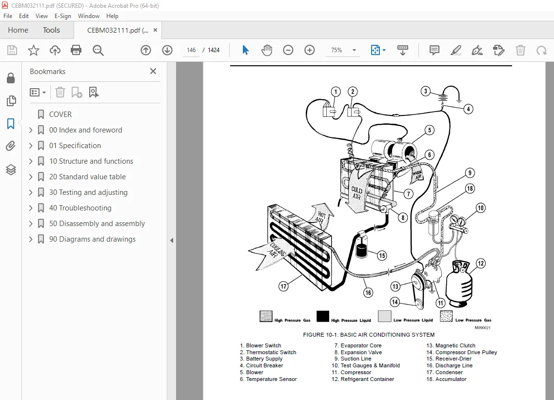
Heating/air conditioning (HVAC) system 143
Basic air conditioning system operation 145
HVAC components 147
Control panel 147
Water valve 147
Expansion valve 147
Actuators 147
Blower 147
Heater core 147
Evaporator core 147
Cab air temperature sensor 147
ECU module 147
Air filters 149
Compressor (refrigerant pump) 149
Compressor clutch 149
Trinary™ switch 150
Receiver-drier 150
Condenser 150
Accumulator 150
Automatic lubrication (auto lube) system 153
General information 155
System operation 156
Engine emissions aftertreatment system 159
About emissions aftertreatment 163
DEF injection system 163
DEF heating system 163
Sensors 163
Exhaust system cleaning 164
Propel lockout precaution 164
Inducement strategy 164
20 Standard value table 167
Standard value table 167
Standard value table for truck 169
30 Testing and adjusting 175
Steering, hoist and auxiliary hydraulic systems 175
Hydraulic system bleeddown procedure 177
Hydraulic system vacuum procedure 179
General information on system checkout 180
Hydraulic system checkout procedures 180
Required equipment 180
Preliminary steps 180
Hydraulic system flushing procedure 181
Flow amplifier adjustment 184
Steering pump unloader valve adjustment 185
Auxiliary accumulator pressure verification 185
System diagnostics 186
Hoist pilot relief valve adjustment 189
Hoist counterbalance valve adjustment 189
Final steps 190
Oil cleanliness check 190
Hydraulic system checkout data sheet 192
Toe-in adjustment 195
Hoist cylinder leakage test 196
Steering cylinder leakage test 196
Brake system 199
General information on system checkout 201
Brake system checkout procedures 201
Required equipment 201
Pre-Checkout Items 201
Bleeddown procedure 203
Preliminary steps 206
Service brakes checks 206
Brake lock system checkout 208
Parking brake system checkout 209
Low Brake Pressure and Auto Apply 210
Brake reapplications (stored energy check) 212
Parking brake control logic check 212
Brake Lock Control Logic Check 213
Brake system checkout data sheet 217
Service brake conditioning (burnishing) 226
Brake burnishing procedure 227
Front brake conditioning 228
Rear brake conditioning 230
Parking brake adjustment procedure 233
Brake bleeding procedure 234
Service brake 234
Parking brake (rear brake calipers only) 234
Piston assembly return spring force and built-in clearance (BIC) 235
Piston assembly adjuster grip force 236
Adjuster force 238
Piston return spring 240
Accumulators and suspensions 243
Accumulator charging and storage 245
Temperature during precharge 245
Bladder accumulator charging procedure 246
Precharge maintenance 248
Bladder accumulator storage procedure 248
Bladder storage 248
Installing a bladder accumulator from storage 249
Bladder accumulator leak testing 249
Piston accumulator charging procedure 250
Piston accumulator storage 253
Piston accumulator leak testing 254
Checking for improper suspension charge on operating trucks 255
Suspension oil change recommendations 256
Suspension oiling and charging procedures 257
Required equipment 257
Installing the charging kit 258
Removing the charging kit 258
Support blocks for oiling and charging dimensions 259
Front suspensions 262
TOP FILL METHOD 263
PRESSURE FILL METHOD 263
Rear suspensions 265
TOP FILL METHOD 267
PRESSURE FILL METHOD 267
Suspension pressure test 269
Electrical systems 271
General information on system checkout 273
Truck shutdown procedure 274
Required software and tools 274
Electrical system checkout procedures 276
Visual inspection 276
Resistance checks 276
Voltage checks 276
Truck function checks 277
Interface module (IM) checks 278
KOMTRAX Plus II checks 278
Payload meter (PLM) checks 278
Drive system checks 279
Engine delayed shutdown Smart Timer check 279
Body hoist limit switch check 279
Electrical checkout sheet 280
Interface module (IM) 285
Required software and tools 287
Interface module checkout procedures 288
Initial startup 288
Checking digital inputs to the IM 288
Checking analog inputs to the IM 290
Checking serial communication to the IM 290
Checking outputs from the IM 290
IM checkout sheet 291
Interface module 2 (IM2) 295
Required tools 297
Programming the IM2 297
Updating the software 297
Configuring the IM2 298
Viewing IM2 real-time data 298
Interface module checkout procedures 299
Checking for IM fault codes 299
Checking digital inputs to the IM 299
Checking analog inputs to the IM 302
Checking serial communication to the IM 302
Checking outputs from the IM 303
IM checkout sheet 304
KOMTRAX Plus II 309
Required software and tools 311
Ethernet connection to KOMTRAX Plus II controller 311
KOMTRAX Plus II configuration 313
GPS connection test 315
Iridium satellite system opening 317
Data download over ethernet connection for KOMTRAX Plus II initialization 320
Payload meter IV 323
Payload meter IV software and tools 325
Payload meter IV system configuration 325
Connecting to the payload meter IV web server 325
Configuring a static IP address 325
Payload meter IV software installation 327
Inclinometer calibration and clean truck tare 328
Payload meter IV checkout procedure 328
PLM IV system checkout data sheet 334
Downloading PLM IV data and possible errors 335
Komatsu wireless bridge (KWB) 339
General information 341
Required software and tools 341
Configuring the Bullet wireless radio 342
Installing the Bullet wireless radio 345
Configuring the NanoStation access point 346
Testing the connection 349
Changing a service computer’s IP address 350
Cab air conditioning 353
General information 355
Service tools and equipment 356
Recovery/recycle station 356
Leak detector 356
Manifold gauge set 357
Service valves 358
Vacuum pump 358
Detecting leaks 359
System performance test 360
Checking system oil 361
System flushing 362
Installing the manifold gauge set 363
Purging air from the service hoses 364
Recovering and recycling refrigerant 365
Draining oil from previous recovery cycle 366
Recovery cycle 366
Recycling procedure 366
Evacuating the air conditioning system 367
Charging the air conditioning system 368
Automatic lubrication (auto lube) system 371
Priming the system 373
Checkout procedure 375
Adjusting the lubrication cycle timing 376
Trucks with Interface Module 1 376
Trucks with Interface Module 2 376
KomVision 379
Requirements 381
Initial setup 382
Checkout data sheet 391
Calibration sheets 396
Layout and assemblage 396
Unfolding a calibration sheet 399
Folding a calibration sheet 400
Placement of calibration sheets 401
Camera calibration procedures 403
Automatic 6 camera calibration 403
Manual 6 camera calibration 407
1 camera calibration 410
Radar setting procedure 413
Tire monitoring system 417
Tire monitoring system software and tools 419
Tire monitoring system configuration 419
Connecting to the tire monitoring system web server 419
Configuring a static IP address 419
Tire monitoring system software installation 421
Tire monitoring system checkout procedure 422
Field Troubleshooting 422
Ethernet troubleshooting 422
Tire monitoring system configuration 423
CAN RPC Troubleshooting 423
Resetting the tire monitoring system 423
Tire monitoring system checkout data sheet 424
40 Troubleshooting 427
Fuse, diode and relay locations 427
Vehicle Electrical Center (VEC-89) 429
Vehicle Electrical Center (VEC-90) 431
Vehicle Electrical Center (VEC-91) 433
Vehicle Electrical Center (VEC-92) 435
Rear Terminal Mini-fuse and Relay (RTMR3) 436
Rear Terminal Mini-fuse and Relay (RTMR4) 437
Circuit breakers 437
Troubleshooting by fault code, Part 1 439
Fault Code A001 442
Fault Code A002 443
Fault Code A003 444
Fault Code A004 445
Fault Code A005 446
Fault Code A006 447
Fault Code A007 448
Fault Code A008 449
Fault Code A009 450
Related circuit diagram 450
Fault Code A010 451
Related circuit diagram 451
Fault Code A011 452
Fault Code A013 453
Fault Code A014 454
Fault Code A016 455
Fault Code A017 456
Fault Code A018 457
Fault Code A019 458
Fault Code A022 459
Fault Code A100 460
Related circuit diagram 460
Fault Code A101 461
Fault Code A103 462
Fault Code A104 463
Fault Code A105 464
Fault Code A109 465
Fault Code A111 466
Fault Code A115 467
Fault Code A117 468
Fault Code A118 469
Fault Code A123 470
Fault Code A124 471
Fault Code A125 472
Fault Code A126 473
Fault Code A127 474
Fault Code A128 475
Fault Code A139 476
Troubleshooting by fault code, Part 2 479
Fault Code A145 482
Fault Code A146 483
Fault Code A152 484
Fault Code A153 485
Fault Code A154 486
Fault Code A155 487
Fault Code A158 488
Fault Code A166 489
Fault Code A167 490
Fault Code A168 491
Fault Code A169 492
Fault Code A170 493
Fault Code A171 494
Fault Code A172 495
Fault Code A173 496
Fault Code A184 497
Fault Code A190 498
Fault Code A193 499
Fault Code A194 500
Fault Code A195 501
Fault Code A196 502
Fault Code A197 503
Fault Code A198 504
Fault Code A199 505
Fault Code A200 506
Fault Code A201 507
Fault Code A202 508
Fault Code A203 509
Fault Code A204 510
Fault Code A205 511
Fault Code A206 512
Fault Code A207 513
Fault Code A213 514
Fault Code A214 515
Fault Code A215 516
Fault Code A216 517
Fault Code A223 518
Fault Code A230 519
Fault Code A231 520
Fault Code A233 521
Fault Code A235 522
Fault Code A236 523
Fault Code A237 524
Fault Code A238 525
Fault Code A239 527
Related circuit diagram 528
Fault Code A240 529
Fault Code A242 530
Fault Code A243 531
Fault Code A244 532
Fault Code A245 533
Fault Code A246 534
Troubleshooting by fault code, Part 3 537
Fault Code A247 540
Fault Code A248 541
Fault Code A249 542
Fault Code A250 543
Fault Code A251 544
Fault Code A252 545
Fault Code A253 546
Fault Code A256 547
Fault Code A257 548
Fault Code A258 549
Fault Code A260 550
Fault Code A261 551
Fault Code A262 552
Fault Code A264 553
Fault Code A265 554
Fault Code A266 555
Fault Code A267 556
Fault Code A268 557
Fault Code A270 558
Fault Code A271 559
Related circuit diagram 560
Fault Code A272 561
Fault Code A273 562
Fault Code A274 563
Fault Code A275 564
Fault Code A277 565
Fault Code A278 566
Fault Code A279 567
Fault Code A280 568
Fault Code A281 569
Fault Code A282 570
Fault Code A283 571
Fault Code A284 572
Fault Code A285 573
Fault Code A286 574
Fault Code A292 575
Troubleshooting by fault code, Part 4 577
Fault Code A303 580
Fault Code A304 581
Fault Code A305 582
Fault Code A307 583
Fault Code A309 584
Fault Code A310 585
Fault Code A311 586
Fault Code A312 587
Fault Code A313 588
Fault Code A315 589
Fault Code A316 590
Fault Code A317 591
Fault Code A318 592
Fault Code A328 593
Fault Code A332 594
Fault Code A333 595
Fault Code A334 596
Fault Code A335 597
Fault Code A337 598
Fault Code A338 599
Fault Code A339 600
Fault Code A340 601
Fault Code A341 602
Fault Code A342 603
Fault Code A343 604
Fault Code A344 605
Fault Code A345 606
Fault Code A346 607
Fault Code A347 608
Fault Code A348 609
Fault Code A349 610
Fault Code A350 611
Fault Code A351 612
Fault Code A352 613
Fault Code A353 614
Fault Code A354 615
Fault Code A355 616
Fault Code A356 617
Fault Code A357 618
Fault Code A358 619
Fault Code A359 620
Fault Code A360 621
Fault Code A361 622
Fault Code A362 623
Fault Code A363 624
Fault Code A364 625
Fault Code A365 626
Fault Code A366 627
Troubleshooting by fault code, Part 5 629
Fault Code A400 632
Fault Code A401 633
Fault Code A402 634
Fault Code A403 635
Fault Code A404 636
Fault Code A405 637
Fault Code A406 638
Fault Code A407 639
Fault Code A408 640
Fault Code A409 641
Fault Code A410 642
Fault Code A411 643
Fault Code A412 644
Fault Code A413 645
Fault Code A414 646
Fault Code A415 647
Fault Code A416 648
Fault Code A417 649
Fault Code A418 650
Fault Code A419 651
Fault Code A420 652
Fault Code A421 653
Fault Code A422 654
Fault Code A423 655
Fault Code A424 656
Fault Code A425 657
Fault Code A426 658
Fault Code A427 659
Fault Code A428 660
Fault Code A429 661
Fault Code A430 662
Fault Code A431 663
Fault Code A432 664
Fault Code A433 665
Fault Code A434 666
Fault Code A435 667
Fault Code A436 668
Fault Code A437 669
Fault Code A438 670
Fault Code A439 671
Fault Code A440 672
Fault Code A441 673
Fault Code A442 674
Fault Code A443 675
Fault Code A444 676
Fault Code A445 677
Fault Code A446 678
Fault Code A447 679
Aftertreatment system fault codes 681
Fault Code CA256 685
Fault Code CA1677 687
Fault Code CA1678 689
Fault Code CA1682 692
Fault Code CA1683 699
Fault Code CA1684 701
Fault Code CA1685 703
Fault Code CA1686 705
Fault Code CA1712 707
Fault Code CA1713 709
Fault Code CA1714 711
Fault Code CA1715 712
Fault Code CA1887 714
Fault Code CA2771 715
Fault Code CA3142 719
Fault Code CA3143 721
Fault Code CA3146 723
Fault Code CA3147 725
Fault Code CA3232 727
Fault Code CA3497 730
Fault Code CA3498 731
Fault Code CA3547 732
Fault Code CA3558 733
Fault Code CA3559 735
Fault Code CA3562 737
Fault Code CA3563 739
Fault Code CA3567 741
Fault Code CA3571 743
Fault Code CA3572 745
Fault Code CA3573 748
Fault Code CA3574 750
Fault Code CA3575 752
Fault Code CA3712 754
Fault Code CA3713 755
Fault Code CA3714 758
Fault Code CA3867 759
Fault Code CA3868 761
Fault Code CA3878 764
Fault Code CA3988 765
Fault Code CA3995 769
Fault Code CA4113 771
Fault Code CA4114 773
Fault Code CA4119 775
Fault Code CA4121 777
Fault Code CA4152 779
Fault Code CA4164 783
Fault Code CA4165 785
Fault Code CA4166 788
Fault Code CA4168 790
Fault Code CA4169 792
Fault Code CA4174 794
Fault Code CA4175 796
Fault Code CA4233 799
Fault Code CA4234 800
Fault Code CA4243 801
Fault Code CA4277 802
Fault Code CA4457 804
Fault Code CA4458 806
Fault Code CA4459 809
Fault Code CA4461 811
Fault Code CA4462 813
Fault Code CA4464 815
Fault Code CA4465 817
Fault Code CA4466 820
Fault Code CA4467 827
Fault Code CA4474 829
Fault Code CA4475 831
Fault Code CA4572 834
Fault Code CA4677 838
Fault Code CA4679 842
Fault Code CA4682 843
Fault Code CA4731 844
Fault Code CA4732 845
Fault Code CA4736 846
Fault Code CA4737 847
Fault Code CA4738 848
Fault Code CA4739 849
Fault Code CA4745 850
Fault Code CA4768 851
Fault Code CA4769 853
Fault Code CA4842 855
Fault Code CA4863 856
Fault Code CA4947 857
Fault Code CA5115 858
Fault Code CA5116 861
Fault Code CA5117 864
Fault Code CA5247 867
Fault Code CA5653 869
Fault Code CA5654 872
Fault Code CA5725 874
Fault Code CA5727 879
Fault Code CA5728 882
Fault Code CA5729 885
Fault Code CA5748 887
Fault Code CA5749 889
Fault Code CA5751 891
Fault Code CA5753 893
Fault Code CA5755 896
Fault Code CA5756 901
Fault Code CA5758 903
Fault Code CA5768 905
Fault Code CA5769 907
Fault Code CA5771 910
Fault Code CA5772 912
Fault Code CA5773 915
Fault Code CA5774 918
Fault Code CA5775 920
Fault Code CA5776 925
Fault Code CA5778 927
Fault Code CA5779 929
Fault Code CA5887 931
Fault Code CA5888 932
Fault Code CA5889 933
Fault Code CA5891 934
Fault Code CA5892 935
Fault Code CA5893 936
Fault Code CA6692 937
Fault Code CA6693 939
Fault Code CA6694 941
Fault Code CA6695 943
Fault Code CA6696 945
Fault Code CA6697 947
Fault Code CA6855 949
Fault Code CA6856 952
Steering system 955
Steering circuit troubleshooting chart 957
Steering circuit troubleshooting guidelines 961
Basic hydraulic system checks 962
System leakage check 963
Steering pump troubleshooting guide 965
Pump pressure control checks 968
Pump fails to unload 969
Pump fails to develop pressure 969
Pump slow in developing pressure 970
Pump control valve inspection and troubleshooting 970
Pump case drain check 972
KomVision 975
KomVision fault codes 977
Automatic lubrication (auto lube) system 987
Autolube troubleshooting chart 989
Heating/air conditioning (HVAC) system 993
Control panel configurations 995
Diagnostics mode 996
Error codes 996
Advanced diagnostics 996
Firmware version 997
Additional HVAC troubleshooting chart 997
Voltage levels 999
Electronic fan clutch 1001
Electronic fan clutch troubleshooting 1003
Electronic fan clutch fault codes 1005
50 Disassembly and assembly 1007
Service tools 1007
Special tool group 1009
Additional service tools 1010
KomVision calibration tools 1010
Locally made tools 1010
Wheels, spindles and rear axle 1013
General precautions for tires and rims 1015
Wheel stud maintenance 1016
Rear outer wheel stud installation 1017
Removal and installation of front wheel 1018
Removal 1018
Installation 1019
Removal and installation of rear wheel 1020
Removal 1020
Installation 1021
Rim Components 1023
Rim and tire service 1024
Lubricants 1024
Tire inflation 1024
Lock ring retainer installation 1024
Remove Smart Lock Ring from Inside Position of Outer Dual and Outside Position of Inner Dual 1025
Install Smart Lock Ring to Inside Position of Outer Dual and Outside Position of Inner Dual 1026
Removal (5-piece standard rim) 1027
Removal (7-piece Smart rim) 1030
Removal (5-piece Smart rim) 1032
Preparation before assembly 1034
Installation (5-piece standard rim) 1034
Installation – horizontal mount (Smart rim) 1036
Installation – vertical mount (5-piece Smart rim) 1038
Installation – vertical mount (7-piece Smart rim) 1040
Removal and installation of front wheel hub and spindle 1041
Removal 1041
Spindle removal (off the truck) 1045
Installation 1047
Disassembly and assembly of front wheel hub and spindle 1048
Cross Section View 1048
Disassembly 1049
Cleaning and inspection 1053
Assembly 1054
Wheel bearing adjustment 1055
Speed sensor installation and adjustment 1057
Floating seal assembly and installation 1058
Removal and installation of rear axle 1064
Removal 1064
Cleaning and inspection 1066
Installation 1066
Removal and installation of anti-sway bar 1067
Removal 1067
Installation 1069
Removal and installation of pivot pin 1070
Removal 1070
Installation 1071
Pivot eye and bearing service 1072
Bearing replacement 1072
Pivot eye repair 1073
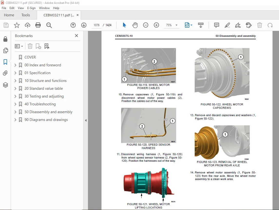
Removal of wheel motor 1074
Preparation 1074
Removal 1074
Installation of wheel motor 1077
Cleaning and inspection 1077
Installation 1078
Brake system 1083
Removal and installation of brake valve 1085
Removal 1085
Installation 1087
Disassembly and assembly of brake valve/pedal assembly 1088
Disassembly 1088
Assembly 1089
Removal and installation of brake manifold 1091
Removal 1091
Installation 1092
Disassembly and assembly of brake manifold 1093
Disassembly 1093
Assembly 1093
Disassembly and assembly of brake accumulator 1094
Cleaning and inspection 1095
Assembly 1096
Removal and installation of front brake caliper 1098
Removal 1098
Inspection 1099
Installation 1099
Disassembly and assembly of front brake caliper 1100
Disassembly 1100
Cleaning and inspection 1100
Brake lining replacement 1103
Assembly 1103
Removal and installation of rear brake caliper 1103
Removal 1103
Inspection 1106
Installation 1106
Disassembly and assembly of rear brake caliper 1110
Disassembly 1110
Piston subassembly 1113
Cleaning and inspection 1114
Assembly 1115
Piston subassembly 1115
Brake caliper 1116
Steering system 1123
Removal and installation of steering control unit 1125
Removal 1125
Installation 1127
Disassembly and assembly of steering control unit 1128
Disassembly 1128
Assembly 1130
Removal and installation of steering column 1133
Removal 1133
Installation 1134
Removal and installation of steering wheel 1135
Removal 1135
Installation 1135
Removal and installation of bleeddown manifold 1136
Removal 1136
Installation 1137
Removal and installation of flow amplifier 1137
Removal 1137
Installation 1138
Removal and installation of steering cylinders and tie rod 1139
Removal 1139
Installation 1139
Disassembly and assembly of steering cylinders 1141
Disassembly 1141
Cleaning and inspection 1143
Assembly 1144
Removal and installation of steering/brake pump 1145
Removal 1145
Installation 1146
Removal and installation of piston steering accumulator 1147
Removal 1147
Installation 1149
Disassembly and assembly of piston steering accumulator 1151
Disassembly 1151
Cleaning and inspection 1153
Piston seal replacement 1153
Assembly 1154
Suspensions 1157
General information 1159
Removal and installation of front suspension 1159
Preparation 1159
Removal 1159
Cleaning and Inspection 1161
Installation 1162
Disassembly and assembly of front suspension 1168
Disassembly 1168
Cleaning and inspection 1170
Assembly 1171
Removal and installation of rear suspension 1173
Removal 1173
Installation 1176
Disassembly and assembly of rear suspension 1179
Disassembly 1179
Cleaning and inspection 1181
Assembly 1182
Hoist circuit 1185
Removal and installation of hoist pump 1187
Removal 1187
Installation 1191
Disassembly and assembly of hoist pump 1192
Disassembly 1192
Inspection 1197
Assembly 1198
Removal and installation of hoist valve 1201
Removal 1201
Installation 1203
Disassembly and assembly of hoist valve 1203
O-ring replacement 1203
Disassembly of inlet section 1205
Assembly of inlet section 1206
Disassembly of spool section 1207
Assembly of spool section 1209
Overcenter manifold service 1210
Removal and installation of hoist pilot valve 1211
Removal 1211
Installation 1211
Disassembly and assembly of hoist pilot valve 1212
Disassembly 1212
Cleaning and inspection 1213
Assembly 1213
Removal and installation of hoist cylinders 1214
Removal 1214
Installation 1217
Disassembly and assembly of hoist cylinders 1220
Disassembly 1220
Cleaning and inspection 1224
Installation of the quill 1225
Installation of check balls and plugs in quill 1226
Assembly 1227
Body and structures 1233
Removal and installation of dump body 1235
Removal 1235
Inspection 1236
Installation 1237
Removal and installation of body pads 1238
Removal 1238
Installation 1238
Body pad shimming procedure 1239
Removal and installation of diagonal ladder/ hood and grille assembly 1240
Removal 1240
Installation 1240
Removal and installation of RH deck 1242
Removal 1242
Installation 1242
Removal and installation of LH deck 1244
Removal 1244
Installation 1244
Removal and installation of fuel tank 1246
Removal 1246
Cleaning and inspection 1246
Installation 1248
Removal and installation of fuel gauge sender 1248
Removal 1248
Installation 1248
Removal and installation of hydraulic tank 1249
Removal 1249
Installation 1250
Removal and installation of hydraulic tank strainers 1251
Removal 1251
Cleaning and inspection 1252
Installation 1252
Operator cab 1255
Removal and installation of operator cab 1257
Removal 1257
Installation 1260
Removal and installation of cab door 1260
Removal 1260
Installation 1261
Disassembly and assembly of cab door 1262
Removing the window regulator 1262
Installing the window regulator 1263
Removing the door glass 1264
Installing the door glass 1265
Replacing the inner door seal 1266
Replacing the outer door seal 1266
Removing the interior door handle and door latch (earlier models) 1267
Installation and removal of interior door handle and door latch (later models) 1270
Adjustment of cab door 1272
Door jamb bolt adjustment 1272
Exterior door handle release button adjustment 1274
Removal and installation of side window glass 1275
Recommended tools and supplies 1275
Removal 1275
Installation 1276
Removal and installation of windshield and rear window glass 1278
Removal 1278
Installation 1278
Removal and installation of windshield wiper components 1279
Removing the windshield wiper motor 1279
Installing the windshield wiper motor 1279
Removing the windshield wiper arm and linkage 1280
Installing the windshield wiper arm and linkage 1281
Removal and installation of cab seats 1281
Removal 1281
Servicing the seat 1282
Installation 1282
Removal and installation of seat belts 1283
Removal 1283
Installation 1284
Power module 1287
Removal and installation of power module 1289
General 1289
Removal 1290
Installation 1299
Exhaust tube installation 1309
Exhaust blanket installation 1309
Removal and installation of alternator 1310
Removal 1310
Installation 1313
Alternator installation checkout data sheet 1323
Removal and installation of radiator 1329
Removal 1329
Installation 1333
Repairing the radiator 1334
Internal inspection 1334
External cleaning 1334
Disassembly 1335
Cleaning and inspection 1336
Assembly 1336
Pressure testing 1337
Removal and installation of engine 1338
Removal 1338
Service 1338
Installation 1339
Removal and installation of electronic fan clutch 1340
Removal 1340
Installation 1341
Removal and installation of electronic fan clutch speed sensor 1341
Removal 1341
Installation 1341
90 Diagrams and drawings 1343
Hydraulic circuit diagrams 1343
Electrical circuit diagrams 1350
DESCRIPTION:
Komatsu 830E-5 Dump Truck Shop Manual CEBM032111 – PDF DOWNLOAD
SERIAL NUMBERS 830E-5 A50005 – A50153
How to read the shop manual
Composition of shop manual
This shop manual contains the necessary technical information for services performed in a workshop.
For ease of understanding, the manual is divided into the following sections.
00. Index and foreword
This section explains the shop manuals list, table of contents, safety, and basic information.
01. Specification
This section explains the specifications of the machine.
10. Structure and function
This section explains the structure and function of each component. The structure and function sub-section
explains the structure and function of each component. It serves not only to give an understanding of
the structure, but also serves as reference material for troubleshooting.
20. Standard value table
This section explains the standard values for new machine and judgment criteria for testing, adjusting,
and troubleshooting. This standard value table is used to check the standard values in testing and adjusting
and to judge parts in troubleshooting.
30. Testing and adjusting
This section explains measuring instruments and measuring methods for testing and adjusting, and
method of adjusting each part. The standard values and judgment criteria for testing and adjusting are
explained in Testing and adjusting.
40. Troubleshooting
This section explains how to find out failed parts and how to repair them. The troubleshooting is divided by
failure modes.
50. Disassembly and assembly
This section explains the special tools and procedures for removing, installing, disassembling, and
assembling each component, as well as precautions for them. In addition, tightening torque and weight of
components are also explained.
90. Diagrams and drawings
This section gives hydraulic circuit diagrams and electrical circuit diagrams.
S.V 28/12/24


