KCM 70Z6 WHEEL LOADER SN.70C7-0101 and up Shop Manual PDF
$32.95
KCM 70Z6 WHEEL LOADER Serial No.70C7-0101 and up P.NO.93208-00831 Shop Manual – PDF DOWNLOAD
Description
KCM 70Z6 WHEEL LOADER Serial No.70C7-0101 and up P.NO.93208-00831 Shop Manual – PDF DOWNLOAD
FILE DETAILS:
KCM 70Z6 WHEEL LOADER Serial No.70C7-0101 and up P.NO.93208-00831 Shop Manual – PDF DOWNLOAD
Language : English
Pages : 743
Downloadable : Yes
File Type : PDF
IMAGES PREVIEW OF THE MANUAL:
TABLE OF CONTENTS:
KCM 70Z6 WHEEL LOADER Serial No.70C7-0101 and up P.NO.93208-00831 Shop Manual – PDF DOWNLOAD
Group 3 Painting W1-3-1-1
PaintingW1-3-1-1
Group 4 Bleeding AirW1-4-1-1
Bleeding Air from Hydraulic Oil TankW1-4-1-1
PreparationW1-4-1-1
Bleeding Air from Hydraulic SystemW1-4-1-2
Bleeding Air from Fuel SystemW1-4-1-3
Bleeding Air from Radiator W1-4-1-4
PreparationW1-4-1-4
Bleeding Air from Brake (Axle) W1-4-1-5
Group 5 Releasing Pressure W1-5-1-1
Front Attachment Hydraulic Circuit Pressure Release
ProcedureW1-5-1-1
Ride Control Accumulator Pressure Release
ProcedureW1-5-1-2
Parking Brake Accumulator Pressure Release
ProcedureW1-5-1-3
Group 6 Preparation W1-6-1-1
Preparation before Inspection and Maintenance
W1-6-1-1
Lock of Frame W1-6-1-2
Machine Position for Inspection and
Maintenance (lift arm raise) W1-6-1-3
SECTION 2 MAINTENANCE STANDARD W2-1-1-1
Group 1 BodyW2-1-1-1
Center HingeW2-1-1-1
Group 2 Front Attachment W2-2-1-1
Pin and BushingW2-2-1-1
Standard Dimensions for Lift Arm and BucketW2-2-2-1
CylinderW2-2-3-1
Rod W2-2-3-1
Rod Bend and Run Out W2-2-3-1
SECTION 3 BODY W3-1-1-1
Group 1 CabW3-1-1-1
Removal and Installation of Cab W3-1-1-1
RemovalW3-1-1-1
InstallationW3-1-1-17
Group 2 Counterweight W3-2-1-1
Removal and Installation of CounterweightW3-2-1-1
RemovalW3-2-1-1
Installation W3-2-1-2
Removal and Installation of Battery BoxW3-2-2-1
RemovalW3-2-2-1
Removal of Battery Box (Right)W3-2-2-1
Removal of Battery Box (Left) W3-2-2-2
Installation W3-2-2-3
Installation of Battery Box (Left)W3-2-2-3
Installation of Battery Box (Right) W3-2-2-4
Group 3 Center Hinge W3-3-1-1
Removal and Installation of Center HingeW3-3-1-1
RemovalW3-3-1-1
InstallationW3-3-1-13
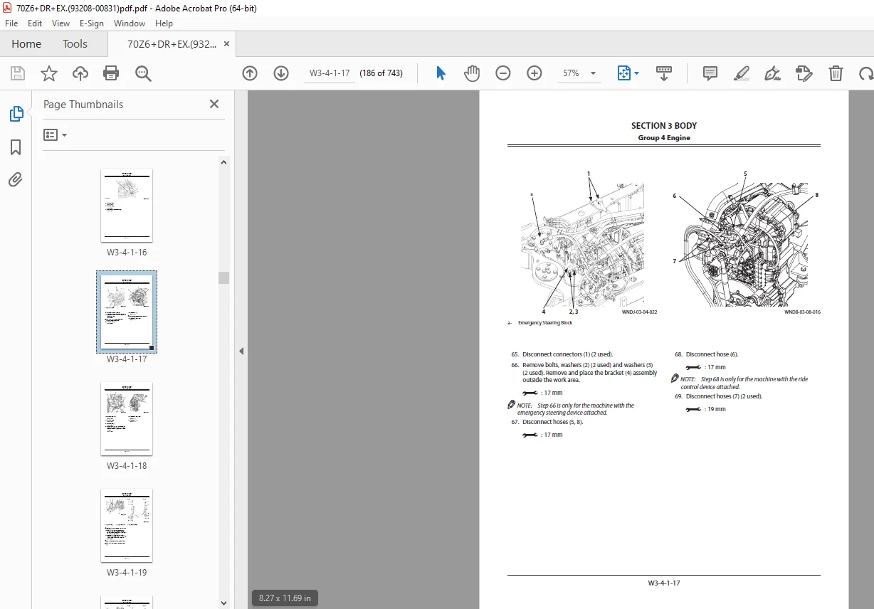
Group 4 Engine W3-4-1-1
Removal and Installation of Engine W3-4-1-1
RemovalW3-4-1-1
InstallationW3-4-1-22
Removal And Installation of Exterior PartsW3-4-2-1
Removal and Installation of Engine Cover (34), Rear Cover
(42), and Covers (Lower) (29, 30)W3-4-2-2
Removal and Installation of Side Covers (Front) (1, 2)
W3-4-2-4
Removal and Installation of Front Fenders (1, 2)
W3-4-2-6
Removal and Installation of Rear Fenders (39, 40), Deck
(01), and Steps (Front) (51, 52, 53) W3-4-2-7
Removal and Installation of Rear Grill (1) W3-4-2-9
Removal and Installation of Inspection Covers (1, 2, 4)
and Steps (Rear) (35, 36, 40) W3-4-2-10
Removal and Installation of Side Covers (Rear) (01, 02)
W3-4-2-11
Group 5 Radiator Assembly W3-5-1-1
Removal and Installation of Radiator, Oil Cooler, Intercooler,
and Torque Converter Cooler W3-5-1-1
RemovalW3-5-1-1
InstallationW3-5-1-15
Group 6 Hydraulic Oil TankW3-6-1-1
Removal and Installation of Hydraulic Oil Tank W3-6-1-1
RemovalW3-6-1-1
InstallationW3-6-1-11
Group 7 Fuel Tank W3-7-1-1
Removal and Installation of Fuel TankW3-7-1-1
RemovalW3-7-1-1
Installation W3-7-1-4
Group 8 Pump Device W3-8-1-1
Removal and Installation of Pump DeviceW3-8-1-1
RemovalW3-8-1-1
Installation W3-8-1-5
Disassembly of Pump Device W3-8-2-1
Disassembly of Pump Device W3-8-2-2
Assembly of Pump DeviceW3-8-2-3
Assembly of Pump Device W3-8-2-4
Disassembly of Main PumpW3-8-3-1
Disassembly of Main Pump W3-8-3-2
Assembly of Main PumpW3-8-3-5
Assembly of Main Pump W3-8-3-7
Disassembly of RegulatorW3-8-4-1
Disassembly of RegulatorW3-8-4-2
Assembly of Regulator W3-8-4-3
Assembly of RegulatorW3-8-4-4
Structure of Pilot PumpW3-8-5-1
CONTENTS
iii
Group 9 Control ValveW3-9-1-1
Removal and Installation of Control ValveW3-9-1-1
RemovalW3-9-1-1
Installation W3-9-1-6
Disassembly of Control Valve W3-9-2-1
Disassembly of Control Valve W3-9-2-2
Assembly of Control ValveW3-9-2-5
Assembly of Control Valve W3-9-2-8
Group 10 Pilot Valve W3-10-1-1
Removal and Installation of Pilot Valve W3-10-1-1
Removal W3-10-1-1
InstallationW3-10-1-4
Removal and Installation of Pilot Valve
(Two Lever Type)W3-10-2-1
Removal W3-10-2-1
InstallationW3-10-2-4
Disassembly of Pilot ValveW3-10-3-1
Disassembly of Pilot ValveW3-10-3-2
Assembly of Pilot Valve W3-10-3-4
Assembly of Pilot ValveW3-10-3-5
Disassembly of Pilot Valve (Two Lever Type) W3-10-4-1
Disassembly of Pilot Valve (Two Lever Type)W3-10-4-3
Assembly of Pilot Valve (Two Lever Type) W3-10-4-7
Assembly of Pilot Valve (Two Lever Type) W3-10-4-9
Group 11 Brake Charge ValveW3-11-1-1
Removal and Installation of Brake Charge Valve
W3-11-1-1
Removal W3-11-1-1
InstallationW3-11-1-4
Structure of Brake Charge Valve W3-11-2-1
Structure of Brake Charge Valve W3-11-2-2
Removal and Installation of Brake Accumulator
W3-11-3-1
Removal W3-11-3-1
InstallationW3-11-3-4
Group 12 Manifold Valve W3-12-1-1
Removal and Installation of Manifold ValveW3-12-1-1
Removal W3-12-1-1
InstallationW3-12-1-6
Disassembly of Manifold Valve W3-12-2-1
Disassembly of Manifold Valve W3-12-2-2
Assembly of Manifold Valve W3-12-2-4
Assembly of Manifold Valve W3-12-2-6
Group 13 Solenoid ValveW3-13-1-1
Removal and Installation of Parking Brake
Solenoid Valve Unit W3-13-1-1
Removal W3-13-1-1
InstallationW3-13-1-3
Structure of Parking Brake Solenoid Valve Unit W3-13-2-1
Group 14 Priority ValveW3-14-1-1
Removal and Installation of Priority ValveW3-14-1-1
Removal W3-14-1-1
InstallationW3-14-1-6
Structure of Priority Valve W3-14-2-1
Group 15 Cooling Fan System W3-15-1-1
Removal and Installation of Fan Motor W3-15-1-1
Removal W3-15-1-1
InstallationW3-15-1-8
Structure of Fan MotorW3-15-2-1
Removal and Installation of Fan PumpW3-15-3-1
Removal W3-15-3-1
InstallationW3-15-3-4
Disassembly of Fan PumpW3-15-4-1
Disassembly of Fan Pump W3-15-4-2
Assembly of Fan PumpW3-15-4-3
Assembly of Fan PumpW3-15-4-4
Group 16 Ride Control Device W3-16-1-1
Removal and Installation of Ride Control Valve W3-16-1-1
Removal W3-16-1-1
InstallationW3-16-1-3
Disassembly of Ride Control ValveW3-16-2-1
Disassembly of Ride Control ValveW3-16-2-2
Assembly of Ride Control ValveW3-16-2-4
Assembly of Ride Control ValveW3-16-2-6
Removal and Installation of Ride Control
AccumulatorW3-16-3-1
Removal W3-16-3-1
InstallationW3-16-3-3
SECTION 4 TRAVEL SYSTEM W4-1-1-1
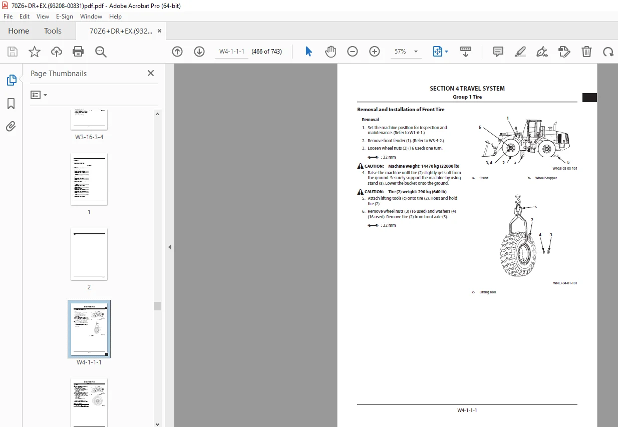
Group 1 Tire W4-1-1-1
Removal and Installation of Front TireW4-1-1-1
RemovalW4-1-1-1
Installation W4-1-1-2
Applicable Tire SizeW4-1-1-3
Removal and Installation of Rear TireW4-1-2-1
RemovalW4-1-2-1
Installation W4-1-2-2
Applicable Tire SizeW4-1-2-3
Group 2 Drive UnitW4-2-1-1
Removal and Installation of Drive Unit W4-2-1-1
RemovalW4-2-1-1
Installation W4-2-1-4
Disassembly and Assembly of Drive UnitW4-2-2-1
Drive Unit AssemblyW4-2-2-1
Detail of Transmission Assembly (2) W4-2-2-2
Removal and Installation of Oil Filter W4-2-2-4
Removal of Oil Filter W4-2-2-5
Installation of Oil FilterW4-2-2-6
Removal and Installation of Torque ConverterW4-2-3-1
Removal of Torque Converter W4-2-3-2
Installation of Torque ConverterW4-2-3-3
Installation of Torque ConverterW4-2-3-4
Disassembly and Assembly of TransmissionW4-2-4-1
Disassembly and Assembly of Hydraulic Pump
Drive W4-2-4-1
Removal of Hydraulic Pump DriveW4-2-4-3
CONTENTS
iv
Assembly of Hydraulic Pump DriveW4-2-4-6
Removal and Installation of Clutch W4-2-4-11
Removal of Clutch, Input Shaft, and
Output ShaftW4-2-4-11
Installation of Clutch, Input Shaft, and
Output ShaftW4-2-4-17
Disassembly and Assembly of Clutch W4-2-4-24
Disassembly of First Speed Clutch (K1), Second Speed
Clutch (K2), and Third Speed Clutch (K3) W4-2-4-27
Assembly of First Speed Clutch (K1), Second Speed Clutch
(K2), and Third Speed Clutch (K3) W4-2-4-31
Disassembly of Slow-Speed Forward Clutch (KV) and
Reverse Clutch (KR)W4-2-4-36
Assembly of Slow-Speed Forward Clutch (KV) and
Reverse Clutch (KR)W4-2-4-38
Disassembly of Fast-Speed Forward Clutch (K4)
W4-2-4-43
Assembly of Fast-Speed Forward Clutch (K4)
W4-2-4-45
Disassembly and Assembly of Transmission
Control ValveW4-2-5-1
Removal and Installation of Transmission
Control Valve W4-2-5-1
Removal of Transmission Control ValveW4-2-5-2
Installation of Transmission Control Valve W4-2-5-3
Removal and Installation of Duct Plate W4-2-5-4
Removal of Duct Plate W4-2-5-5
Assembly of Duct Plate W4-2-5-6
Disassembly and Assembly of Transmission
Control Valve W4-2-5-7
Disassembly of Transmission Control ValveW4-2-5-8
Assembly of Transmission Control ValveW4-2-5-9
Removal and Installation of Parking Brake (Replace The
Brake Friction Pad)W4-2-6-1
RemovalW4-2-6-1
Installation W4-2-6-3
Adjustment of parking brake W4-2-6-5
The manual release of the parking brake W4-2-6-6
Removal and Installation of Flange at Output
Shaft Side W4-2-6-7
RemovalW4-2-6-7
Installation W4-2-6-8
Group 3 Axle W4-3-1-1
Removal and Installation of Front AxleW4-3-1-1
RemovalW4-3-1-1
Installation W4-3-1-4
Removal and Installation of Rear AxleW4-3-2-1
RemovalW4-3-2-1
Installation W4-3-2-5
Disassembly of Axle W4-3-3-1
Disassembly of Axle W4-3-3-1
Assembly of AxleW4-3-3-2
Assembly of Axle W4-3-3-2
Group 4 Propeller Shaft W4-4-1-1
Removal and Installation of Propeller Shaft W4-4-1-1
RemovalW4-4-1-1
Installation W4-4-1-6
Group 5 Brake Valve W4-5-1-1
Removal and Installation of Brake Valve
(One Pedal)W4-5-1-1
RemovalW4-5-1-1
Installation W4-5-1-3
Removal and Installation of Brake Valve
(Two Pedals)W4-5-2-1
RemovalW4-5-2-1
Installation W4-5-2-3
Disassembly of Brake Valve W4-5-3-1
Disassembly of Brake Valve W4-5-3-2
Assembly of Brake ValveW4-5-3-4
Assembly of Brake Valve W4-5-3-7
Group 6 Steering DeviceW4-6-1-1
Removal and Installation of Steering ValveW4-6-1-1
RemovalW4-6-1-1
Installation W4-6-1-3
Disassembly of Steering Valve W4-6-2-1
Disassembly of Steering Valve W4-6-2-2
Assembly of Steering Valve W4-6-2-4
Assembly of Steering Valve W4-6-2-6
Removal and Installation of Steering CylinderW4-6-3-1
RemovalW4-6-3-1
Removal of Steering Cylinder (Left) W4-6-3-1
Removal of Steering Cylinder (Right)W4-6-3-4
Installation W4-6-3-7
Installation of Steering Cylinder (Right) W4-6-3-7
Installation of Steering Cylinder (Left) W4-6-3-11
Disassembly of Steering Cylinder W4-6-4-1
Disassembly of Steering Cylinder W4-6-4-2
Assembly of Steering CylinderW4-6-4-5
Assembly of Steering Cylinder W4-6-4-6
Removal and Installation of Steering Accumulator
W4-6-5-1
RemovalW4-6-5-1
Installation W4-6-5-2
Group 7 Emergency Steering DeviceW4-7-1-1
Removal and Installation of Emergency
Steering Pump W4-7-1-1
RemovalW4-7-1-1
Installation W4-7-1-4
SECTION 5 FRONT ATTACHMENTW5-1-1-1
Group 1 Front Attachment W5-1-1-1
Removal and Installation of Front Attachment
(With Lift Arm Kickout) W5-1-1-1
RemovalW5-1-1-1
Position to Install (Lift Arm) W5-1-1-6
Installation W5-1-1-6
Direction to Install (Lift Arm)W5-1-1-6
Position to Install (Bucket Cylinder) W5-1-1-7
CONTENTS
v
Direction to Install (Bucket Cylinder) W5-1-1-7
Removal and Installation of Front Attachment
(With Lift Arm Auto Leveler) W5-1-2-1
RemovalW5-1-2-1
Position to Install (Lift Arm) W5-1-2-7
Installation W5-1-2-7
Direction to Install (Lift Arm)W5-1-2-7
Position to Install (Bucket Cylinder) W5-1-2-8
Direction to Install (Bucket Cylinder) W5-1-2-8
Removal and Installation of Bell Crank W5-1-3-1
Position to Install (Bell Crank) W5-1-3-4
Installation W5-1-3-4
Direction to Install (Bell Crank)W5-1-3-4
Position to Install (Bucket Link)W5-1-3-5
Direction to Install (Bucket Link) W5-1-3-5
Position to Install (Bucket Cylinder) W5-1-3-6
Direction to Install (Bucket Cylinder) W5-1-3-6
Removal and Installation of Bucket W5-1-4-1
RemovalW5-1-4-1
Position to Install (Lift Arm) W5-1-4-3
Installation W5-1-4-3
Direction to Install (Lift Arm)W5-1-4-3
Direction of Install (Bucket Link) W5-1-4-4
Direction to Install (Bucket Link) W5-1-4-4
Group 2 Cylinder W5-2-1-1
Removal and Installation of Lift Arm Cylinder W5-2-1-1
RemovalW5-2-1-1
Position to Install (Lift Arm Cylinder) W5-2-1-4
Installation W5-2-1-4
Direction to Install (Lift Arm Cylinder) W5-2-1-4
Removal and Installation of Bucket Cylinder W5-2-2-1
RemovalW5-2-2-1
Position to Install (Bucket Cylinder) W5-2-2-6
Installation W5-2-2-6
Direction to Install (Bucket Cylinder) W5-2-2-6
Disassembly of Lift Arm Cylinder and Bucket
CylinderW5-2-3-1
Lift Arm Cylinder W5-2-3-1
Bucket CylinderW5-2-3-2
Disassembly of Lift Arm Cylinder and Bucket
Cylinder W5-2-3-3
Assembly of Lift Arm Cylinder and Bucket Cylinder
W5-2-3-6
Lift Arm Cylinder W5-2-3-6
Bucket CylinderW5-2-3-7
Assembly of Lift Arm Cylinder and Bucket
Cylinder W5-2-3-8
DESCRIPTION:
KCM 70Z6 WHEEL LOADER Serial No.70C7-0101 and up P.NO.93208-00831 Shop Manual – PDF DOWNLOAD
TO BE READER:
- This manual is written for an experienced technician to provide technical information needed to maintain and repair this machine.
- Be sure to thoroughly read this manual for correct product information and service procedures.
Manual Composition:
- Our shop manuals consist of the Technical Manual, the Workshop Manual and the Engine Manual.
- Information included in the Technical Manual: Technical information needed for machine pre-delivery and delivery, operation and activation of all devices and systems, operational performance tests, and troubleshooting procedures.
- Information included in the Workshop Manual: Technical information needed for maintenance and repair of the machine, tools and devices needed for maintenance and repair, maintenance standards, and removal / installation and assembly / disassembly procedures.
- Information included in the Engine Manual: Technical information needed for machine pre-delivery and delivery and maintenance and repair of the machine, operation and activation of all devices and systems, troubleshooting and assembly / disassembly procedures.
G.B 28/01/25