KCM 70Z6/80ZZ6 Cummins QSB6.7Engine Wheel Loader Operation & Maintenance Manual PDF
$28.95
KCM 70Z6/80ZZ6 Wheel Loader Cummins QSB6.7 Engine Operation & Maintenance Manual – PDF DOWNLOAD
Description
KCM 70Z6/80ZZ6 Cummins QSB.67 Engine Wheel Loader Operation & Maintenance Manual – PDF DOWNLOAD
FILE DETAILS:
KCM 70Z6/80ZZ6 Wheel Loader Cummins QSB6.7 Engine Operation & Maintenance Manual – PDF DOWNLOAD
Language : English
Pages : 398
Downloadable : Yes
File Type : PDF
IMAGES PREVIEW OF THE MANUAL:
TABLE OF CONTENTS:
KCM 70Z6/80ZZ6 Wheel Loader Cummins QSB6.7 Engine Operation & Maintenance Manual – PDF DOWNLOAD
MACHINE NUMBERS 1
SAFETYS-1
Recognize Safety Information S-1
Understand Signal Words S-1
Follow Safety Instructions S-2
Prepare for Emergencies S-3
Wear Protective Clothing S-3
Protect Against NoiseS-4
Inspect Machine S-4
General Precautions for CabS-5
Use Handrails and Steps S-6
Never Ride AttachmentS-6
Adjust Operator’s Seat S-6
Ensure Safety Before Rising from or Leaving Operator’s Seat S-7
Fasten Your Seat Belt S-7
Move and Operate Machine Safely S-8
Handle Starting Aids Safely S-8
Operate Only from Operator’s Seat S-9
Jump StartingS-9
Investigate Job Site Beforehand S-10
Equipment of Head Guard, ROPS, FOPS S-11
Provide Signals for Jobs Involving Multiple Machines S-11
Keep Riders Off MachineS-12
Drive Safely S-12
Drive Machine Safely (Work Site)S-13
Drive Safely with Bucket LoadedS-14
Drive on Snow Safely S-14
Travel on Public Roads Safely S-15
Avoid Injury from Rollaway Accidents S-15
Avoid Accidents from Backing Up and Turning S-16
Avoid Positioning Bucket or Attachment Over Anyone S-17
Avoid Tipping S-17
Never Undercut a High Bank S-18
Dig with Caution S-18
Perform Truck Loading SafelyS-18
Avoid Power Lines S-19
Precautions for Operation S-19
Precautions for Lightning S-19
Object Handling S-20
Protect Against Flying DebrisS-20
Park Machine Safely S-21
Avoid Injury from Attachment Falling Accident S-21
Transport Safely S-22
Handle Fluids Safely−Avoid FiresS-23
Practice Safe Maintenance S-24
Warn Others of Service Work S-25
Support Machine ProperlyS-25
Stay Clear of Moving PartsS-26
Support Maintenance ProperlyS-26
Prevent Parts from Flying S-27
Prevent Burns S-27
Replace Rubber Hoses Periodically S-28
Avoid High-Pressure Fluids S-28
Prevent FiresS-29
Evacuating in Case of Fire S-31
Beware of Exhaust Fumes S-31
Precautions for Welding and Grinding S-31
Avoid Heating Near Pressurized Fluid LinesS-32
Avoid Applying Heat to Lines Containing Flammable Fluids S-32
Precautions for Handling Accumulator and Gas Damper S-32
Remove Paint Before Welding or Heating S-33
Beware of Asbestos and Silicon Dust and Other Contamination S-33
Prevent Battery Explosions S-34
Service Air Conditioning System Safely S-34
Handle Chemical Products Safely S-35
Dispose of Waste Properly S-35
Precautions for Communication Terminal S-36
Precaution for Communication Terminal EquipmentS-37
SAFETY SIGNS S-39
COMPONENTS NAME 1-1
Components Name 1-1
GETTING ON/OFF THE MACHINE 1-2
Getting ON/OFF the Machine1-2
OPERATOR’S STATION1-3
Cab Features1-3
Front Console 1-4
Right Console 1-5
Fingertip Control Type 1-5
Multi-Function Joystick Type 1-6
Monitor Panel1-7
Service Indicator (Yellow) 1-8
Parking Brake Indicator (Red)1-9
Brake Oil Low Pressure Indicator (Red) 1-9
Low Steering Oil Pressure Indicator (Red) (Optional) 1-9
Transmission Warning Indicator (Red) 1-10
Discharge Warning Indicator (Red) 1-10
Engine Trouble Indicator (Red) 1-10
Overheat Indicator (Red)1-11
Engine Oil Low Pressure Indicator (Red) 1-11
Air Filter Restriction Indicator (Red) 1-11
Preheat Indicator (Yellow) 1-12
Emergency Steering Indicator (Yellow) (Optional) 1-12
Seat Belt Indicator (Red) 1-13
Hydraulic Oil Temperature Indicator (Red)1-13
Transmission Oil Temperature Indicator (Red) 1-13
Coolant Temperature Gauge 1-14
Fuel Gauge1-14
Transmission Oil Temperature Gauge1-14
Turn Signal Indicator (Green) 1-15
High Beam Indicator (Blue) 1-15
Work Light Indicator (Yellow) 1-15
Clearance Light Indicator (Green) 1-16
Control Lever Lock Indicator (Red)1-16
Power Mode Indicator (Blue) 1-16
Maintenance Indicator 1-17
CONTENTS
Forward/Reverse Selector Switch Indicator (Green) (Optional)1-17
Fan Reverse Rotation Indicator (Green) (Optional) 1-17
Monitor Display1-18
Forward/Reverse and Shift Position Indicator1-19
Speedometer 1-21
Ride Control Indicator (Optional)1-22
ECO Indicator 1-22
Machine Information Display 1-23
Shifting Item to be Indicated on Machine Information Display1-24
Resetting of Oil Change and Filter Replacement Intervals1-28
Hydraulic Oil Change Interval Hour Meter1-28
Hydraulic Oil Filter 1 Replacement Interval Hour Meter1-29
Hydraulic Oil Filter 2 Replacement Interval Hour Meter1-30
Transmission Oil Change Interval Hour Meter 1-31
Transmission Oil Filter Replacement Interval Hour Meter1-32
Engine Oil Change Interval Hour Meter 1-33
Engine Oil Filter Replacement Interval Hour Meter 1-34
Fuel Filter Replacement Interval Hour Meter 1-35
Axle Oil Change Interval Hour Meter 1-36
Clock Setting Mode 1-37
Clock (24H) Setting Procedures1-37
Switches, Steering Wheel and Pedals 1-38
Forward/Reverse Lever/ Shift Switch 1-39
Forward/Reverse Lever 1-39
Shift Switch 1-39
Neutral Lever Lock (for the Forward/Reverse Lever) 1-40
Steering1-40
Horn Switch 1-40
Turn Signal Lever1-41
Light Switch 1-42
High-Low Beam Switch1-43
Key Switch 1-43
Wiper Switch 1-44
Wiper Operation 1-44
Front/Rear Wiper Switch 1-45
Hazard Switch1-46
Work Light Switch 1-47
Parking Brake Switch 1-48
Accelerator Pedal1-49
Brake Pedal 1-49
Service Brake 1-49
Clutch Cut Off Brake 1-49
Tilt Lever 1-50
Travel Mode Selector 1-51
Clutch Cut Position Switch1-52
Shift Change Delay Mode Switch (Optional) 1-53
Right Console / Switches1-54
Fingertip Control Type 1-54
Control Lever 1-55
Right Console / Switches1-57
Multi-Function Joystick Type 1-57
Multi-Function Joystick Lever 1-58
Control Lever Lock Switch 1-59
Armrest Adjust Handle 1-60
1st Speed Fixed Switch 1-61
Power Mode Switch 1-62
Quick Power Switch 1-63
Hold Switch 1-64
DSS (Down Shift Switch) 1-65
Ride Control Switch (Optional) 1-66
AUTO 1-66
OFF1-66
Fan Reverse Rotation Switch (Optional) 1-67
Manual Operation 1-67
AUTO1-68
Forward/Reverse Selector Switch (Optional) 1-69
Operational Procedure 1-69
Emergency Steering Operation Check Switch (Optional)1-70
Dual Lift Arm Auto Leveler (Optional) 1-71
Cigar Lighter1-72
Using Cigar Lighter1-72
Using Cigar Lighter Port as External Power Source 1-72
Ash Tray1-73
Auto Air Conditioner 1-74
Feature 1-74
Components Name 1-75
Controller Part Name and Function 1-76
Defroster Operation 1-80
Cool Head/Warm Feet Operation1-80
Tips for Optimal Air Conditioner Usage 1-81
For Rapid Cooling 1-81
For Rapid Warming1-81
When Windows Become Clouded 1-82
Off-Season Air Conditioner Maintenance 1-82
Adjusting Operator’s Seat (Mechanical Suspension Type Seat) 1-83
Adjusting Operator’s Seat (Mechanical Suspension Type Seat) (Optional) 1-85
Adjusting Operator’s Seat (Air Suspension Type Seat) (Optional)1-88
Components Name 1-88
Rear Tray 1-93
Electric Power Output (Optional) 1-93
Fuse Box 1-94
Fuse Box A 1-95
Fuse Box B 1-95
Hot/Cool Box 1-96
Tray and Drink Holder1-96
Cab1-97
Front Room Light 1-99
Rear Room Light 1-99
Sun Visor 1-100
Emergency Exit 1-100
Coat Hook 1-100
Upper Switch Panel (Optional) 1-101
CONTENTS
Rotary Light Switch (Optional) 1-101
AM/FM Radio Operation 1-102
Audio Input1-105
Outside Rear View Mirror 1-106
Room Rear View Mirror 1-106
Cab Door 1-106
Door Open/Close Lever 1-107
Window Open/Close Levers 1-107
When Fully Opening the Left Door1-108
Cab Door Release Lever1-108
Battery Disconnect Switch (Optional) 1-109
Switch Operation 1-110
Articulation Lock Bar1-111
Towing Pin 1-112
Inspection/Maintenance Side Access Cover 1-113
Rear Grille1-114
Steps1-115
Tool Box 1-115
Vandal-Proof Devices 1-116
Seat Belt1-118
Seat Belt1-118
Seat Pocket1-118
BREAK-IN 2-1
Break-in Operation for New Machine 2-1
OPERATING ENGINE 3-1
Inspect Machine Daily Before Starting 3-1
Check Before Starting3-3
Starting Engine3-5
Starting in Cold Weather3-7
Check After Starting3-8
Using Booster Batteries3-9
Warming Up Operation3-11
Warming Up Operation in Cold Weather3-12
Stopping Engine 3-14
DRIVING MACHINE4-1
Driving the Machine4-1
Starting to Move 4-2
Power Mode Switch 4-6
Shift Change Delay Mode (Optional) 4-7
Parking Brake Switch 4-8
Drive Speed Change 4-9
Changing Forward/Reverse Drive Direction4-9
Steering Wheel 4-10
Emergency Steering (Optional)4-11
Stop and Restart of Driving 4-12
Precautions for Driving on Slopes 4-15
Precautions to be Taken if Machine Failure Occurs 4-16
Stop the Machine 4-17
Parking 4-19
Emergency Evacuation 4-20
OPERATING MACHINE5-1
Control Lever 5-1
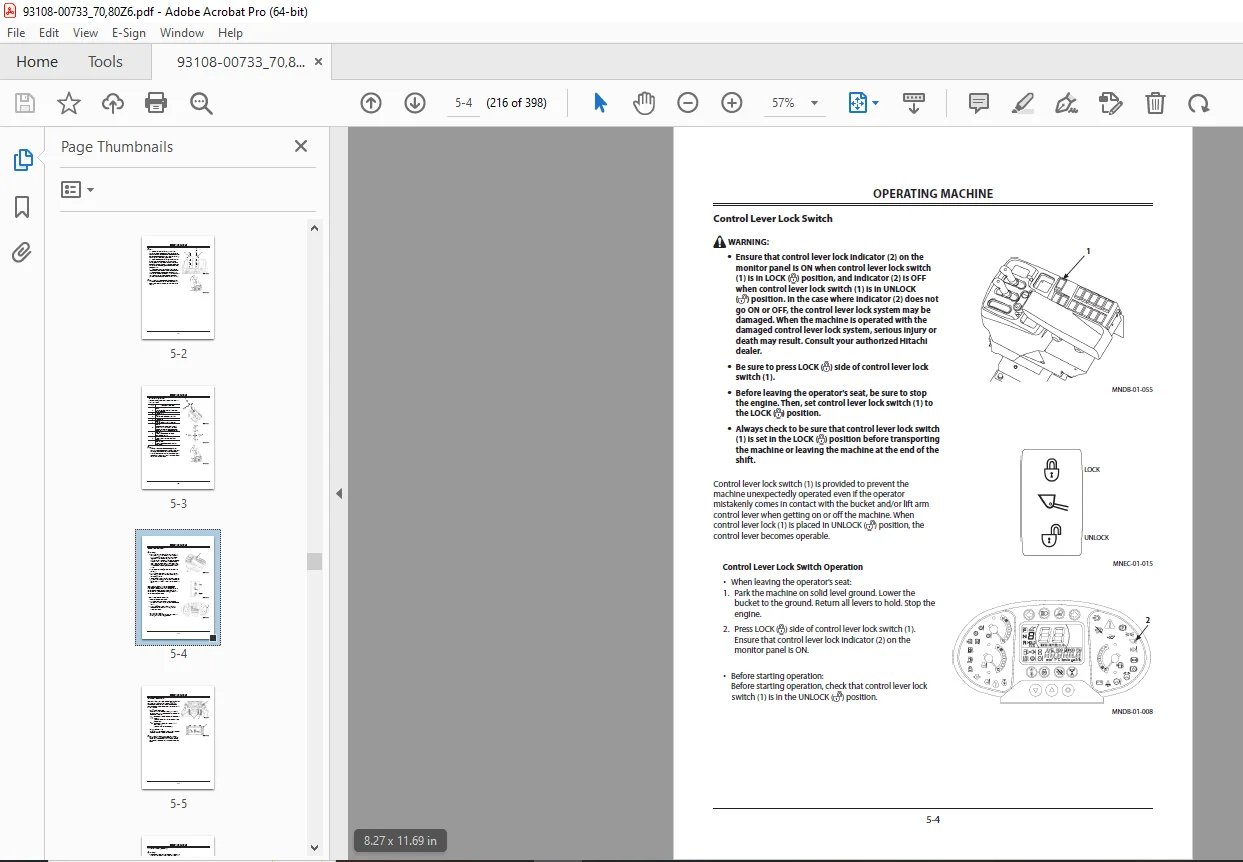
Control Lever Lock Switch 5-4
Clutch Cut Position Switch5-5
Ride Control Switch (Optional) 5-6
Lift Arm Kick Out 5-8
Dual Lift Arm Auto Leveler (Optional) 5-9
Bucket Auto Leveler5-10
Before Operation5-12
Precautions for Operation 5-12
Ensure Safety When Operating on Road Shoulders5-12
Avoid Overloading5-13
Avoid Rapid Steering Changes and/or Sudden
Braking 5-13
Avoid Operation with Biased Loads5-13
Excavation 5-14
Grading5-16
Loading5-17
Dozing 5-20
Scooping5-20
Removing Snow 5-21
Lifting Wheel Loader 5-21
Precautions for After Operations5-22
TRANSPORTING6-1
Transporting by Road6-1
Transporting by Trailer 6-1
Loading / Unloading on Trailer 6-2
Fastening Machine for Transporting 6-4
Transporting Wheel Loader (Urgent Situation)6-5
Towing Method6-9
Lifting Machine6-10
MAINTENANCE 7-1
Correct Maintenance and Inspection Procedures 7-1
Check the Hour Meter Regularly 7-3
Layout7-4
Preparations for Inspection and Maintenance 7-7
Lock Frames 7-9
Inspection/Maintenance Access Side Cover7-10
Rear Grille 7-11
Maintenance Guide 7-12
Periodic Replacement of Parts 7-18
Kind of Oils7-19
AGreasing7-22
BEngine 7-27
Check Engine Oil Level 7-27
Change Engine Oil 7-28
Replace Engine Oil Filter 7-30
Check Crankcase Breather Tube 7-31
Check Vibration Damper 7-32
CPower Train7-33
Check Transmission Oil Level 7-33
Change Transmission Oil and Transmission Oil
Filter 7-34
Change Axle Oil7-37
Check Oil Level 7-38
Check Surroundings Around Axle for Oil Leaks7-39
Clean Axle Housing Air Breather 7-39
DHydraulic System 7-40
Inspection and Maintenance of Hydraulic Equipment 7-40
CONTENTS
Check Hydraulic Oil Level 7-42
Change Hydraulic Oil/Clean Hydraulic Oil Tank7-43
Bleed Air from the Hydraulic System 7-44
Clean Suction Filter 7-45
Replace Pilot Oil Filter7-46
Replace Hydraulic Tank Oil Filter 7-48
Replace Air Breather Element 7-50
Check Pilot Circuit Accumulator Function, Gas
Leakage, Looseness, and Damage 7-51
Replace Pilot Circuit Accumulator 7-52
Check Ride Control Accumulator Function, Gas
Leakage, Looseness, and Damage (Optional) 7-52
Check Gas Pressure in Ride Control Accumulator (Optional)7-52
Check Gas Pressure in Steering Accumulator 7-52
Check Hoses and Lines 7-53
EFuel System7-58
Check Fuel Level 7-58
Drain Water and Sediment from Fuel Tank7-60
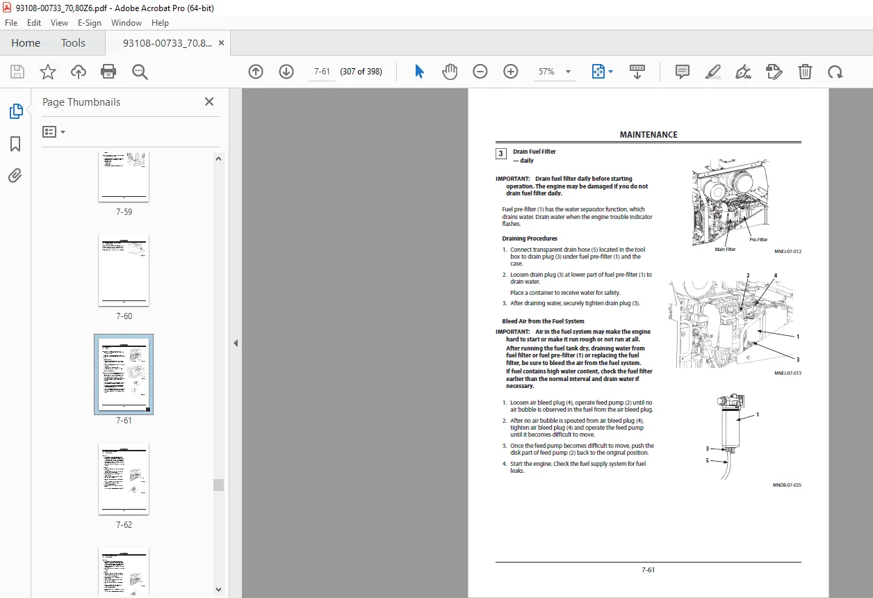
Drain Fuel Filter 7-61
Bleed Air from the Fuel System 7-61
Replace Fuel Main Filter Element7-62
Replace Fuel Pre-Filter Element7-63
Clean Fuel Solenoid Pump Strainer 7-64
Check Fuel Hoses7-65
FAIR CLEANER 7-66
Air Cleaner Outer Element 7-66
Air Cleaner Inner Element 7-66
Check Air Inlet System 7-67
GCooling System 7-68
Check Coolant Level7-69
Check Drive Belt 7-70
Check and Adjust Drive Belt Tension7-70
Change Coolant7-71
Clean Radiator/Oil Cooler and Other Cooling
System7-72
HElectrical System 7-73
Batteries 7-73
Check Monitor Functions and All Other Instrument Operation7-77
Check Lights7-78
Check Horn and Reverse Buzzer 7-79
Check Electrical Harnesses and Fuses7-80
Fuse Box A 7-81
Fuse Box B 7-81
IBrake System 7-82
Check Right and Left Brake Interlocking
Performance 7-82
Check Parking Brake Force7-83
Check Accumulator Function, Gas Leakage,
Looseness, and Damage 7-84
Check Gas Pressure in Accumulator 7-85
Check Brake Disks (Service and Parking) 7-85
JTire7-86
Check and Replace Tire (Tire Pressure) 7-86
Check Tire for Damage 7-86
Check Wheel Nut Torque 7-87
Removal and Installation of Tire 7-91
KAir Conditioner 7-92
Clean/Replace Air Conditioner Circulation/Fresh
Air Filters 7-92
Check Air Conditioner7-96
Check Air Conditioner Piping 7-96
Check Air Conditioner Condenser 7-97
Check Air Conditioner Fan Belt 7-97
Check Refrigerant 7-98
Check Compressor and Pulley7-98
MMiscellaneous7-99
Check Bucket Teeth and Cutting Edge 7-99
Check and Replace Seat and Seat Belt7-100
Check Cab and Roof Mounting Bolts7-100
Check Windshield Washer Fluid Level 7-100
Check Play Amount in Steering Wheel Stroke 7-101
Check Accelerator Pedal Operation, and Exhaust
Gas Color and Noise 7-102
Check Rearview Mirror and Inside Rearview
Mirror7-103
Check Steps and Handrails for Damage and
Looseness 7-103
Clean Engine Compartment and Hood 7-104
Check Sound Absorbing Mat Around Engine 7-104
Check and Adjust Valve Clearance 7-104
Retighten Front Axle and Rear Axle Support
Mounting Bolts7-105
Tightening and Retightening Torque of Nuts and
Bolts7-106
MAINTENANCE UNDER SPECIAL ENVIRONMENTAL CONDITIONS 9-1
Maintenance Under Special Environmental Conditions 9-1
Precautions for Maintenance During Cold Weather
Season9-2
STORAGE 10-1
Storing the Machine10-1
TROUBLESHOOTING11-1
SPECIFICATIONS 12-1
Specifications 12-1
OPTIONAL ATTACHMENTS13-1
Hydraulic Type Quick Coupler Operation 13-1
Log Grapple Operation13-4
Part Locations 13-4
Operation13-4
Clamp Arm Control Lever 13-4
Loading and Unloading 13-5
Working Position13-7
General Work 13-7
Carrying Position13-7
Picking Up Operation (One log) 13-8
Truck Loading13-9
INDEX14-1
DESCRIPTION:
KCM 70Z6/80ZZ6 Wheel Loader Cummins QSB6.7 Engine Operation & Maintenance Manual – PDF DOWNLOAD
G.B 29/01/24