Kawasaki WHEEL LOADER DOZER SPEC 95ZV OPERATION & MAINTENANCE MANUAL 93115-00190 PDF
$30.95
Kawasaki WHEEL LOADER DOZER SPEC 95ZV OPERATION & MAINTENANCE MANUAL 93115-00190 – PDF DOWNLOAD
CUMMINS QSX15 Engine
Serial No. 97C4-0140
WHEEL LOADER
DOZERSPEC
Description
Kawasaki WHEEL LOADER DOZER SPEC 95ZV OPERATION & MAINTENANCE MANUAL 93115-00190 – PDF DOWNLOAD
FILE DETAILS:
Kawasaki WHEEL LOADER DOZER SPEC 95ZV OPERATION & MAINTENANCE MANUAL 93115-00190 – PDF DOWNLOAD
Language :English
Pages :533
Downloadable : Yes
File Type : PDF
IMAGES PREVIEW OF THE MANUAL:
DESCRIPTION:
Kawasaki WHEEL LOADER DOZER SPEC 95ZV OPERATION & MAINTENANCE MANUAL 93115-00190 – PDF DOWNLOAD
CUMMINS QSX15 Engine
Serial No. 97C4-0140
WHEEL LOADER
DOZERSPEC
Foreword
To ensure good machine performance, reduce failures or problems, and prolong the service life of each component,
it is necessary to operate the machine as is directed in the Operator and Maintenance Manual.
To effectively diagnose and repair the machine, it is important to follow the guidelines laid out in this Shop Manual.
General Information
Function and structure
For the engine, refer to the engine Shop Manual provided by the engine manufacturer.
The purpose of this manual is to provide information on the product and the correct maintenance and repair methods.
Please read this manual to ensure correct troubleshooting and good repair service.
This manual will be periodically reviewed and revised for more satisfactory content. If you have any opinion or
requests, please inform us.
TABLE OF CONTENTS:
Kawasaki WHEEL LOADER DOZER SPEC 95ZV OPERATION & MAINTENANCE MANUAL 93115-00190 – PDF DOWNLOAD
CUMMINS QSX15 Engine
Serial No. 97C4-0140
WHEEL LOADER
DOZERSPEC
Foreword 4
Safety Symbols 5
CONTENTS 6
00 General Information 18
How to Use Manual 19
Outline 21
03 Measurement for Performance Check 40
Cautions on Safety 41
Standard Measurement Values for Performance Check 42
12 Function & Structure Chassis Group 48
Front Chassis 49
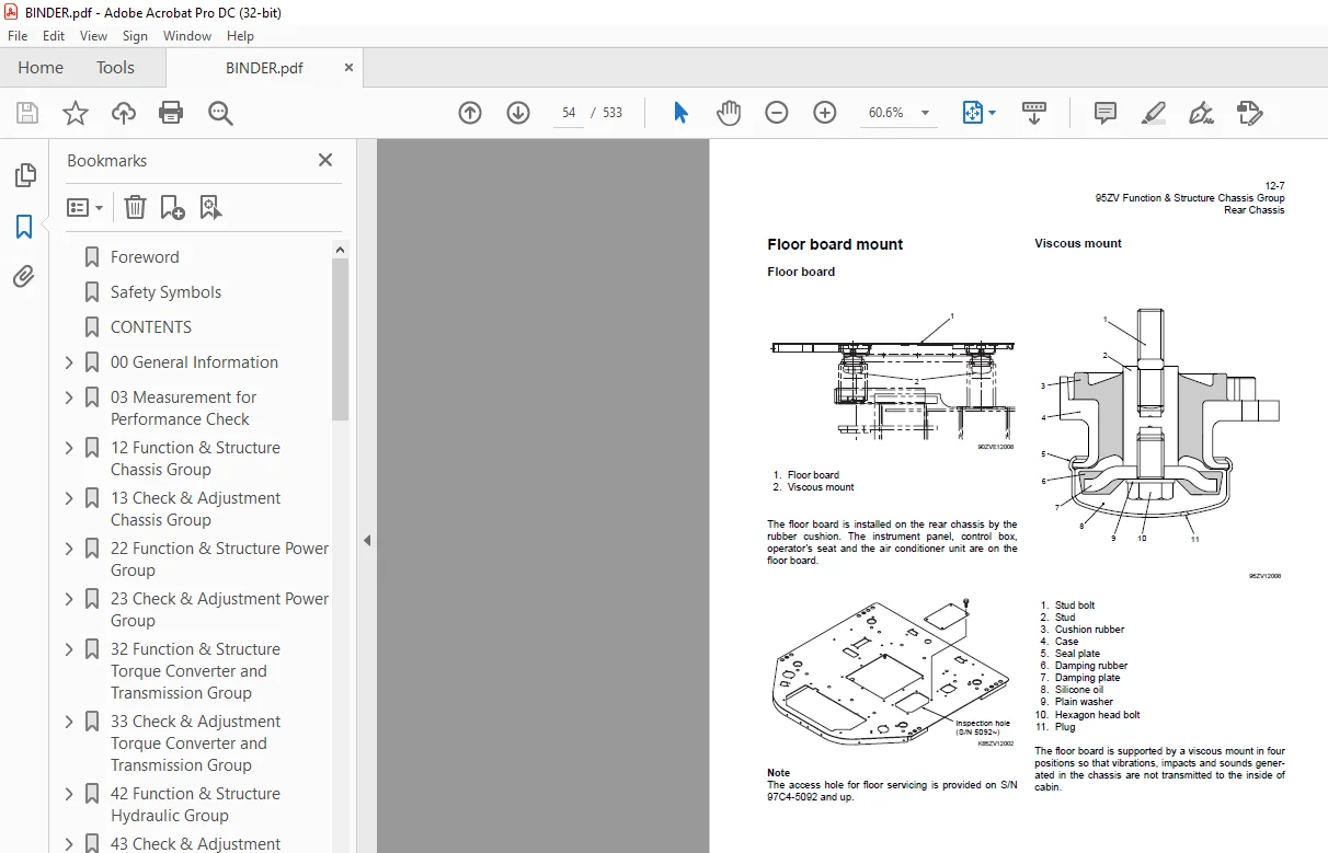
Rear Chassis 52
Center Pin 55
13 Check & Adjustment Chassis Group 58
Linkage Pin 59
Center Pin 62
22 Function & Structure Power Group 64
Power Line 65
Engine / Transmission 66
Radiator 67
Propeller Shaft 69
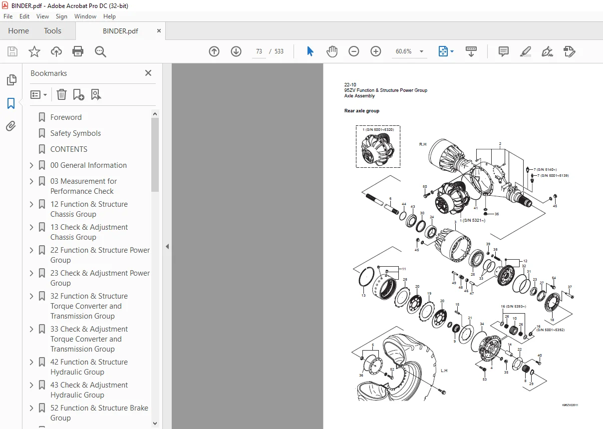
Axle Assembly 72
Axle Support 75
Differential Gear 81
23 Check & Adjustment Power Group 88
Engine 89
Propeller Shaft 90
Axle 92
32 Function & Structure Torque Converter and Transmission Group 98
Torque Converter 99
Torque Converter Gear Pump 100
Transmission 102
Clutch Pack 106
Power Flow Path in the Transmission 107
Hydraulic System Diagram 112
Hydraulic Circuit Diagram 113
Oil Flow 114
T/C and T/M Oil Circulation 115
Modulator Valve Unit 116
Clutch Solenoid Valve 122
33 Check & Adjustment Torque Converter and Transmission Group 126
Clutch Oil Pressure and Time Lag 127
42 Function & Structure Hydraulic Group 130
Flushing Hydraulic Circuit 131
Cautions on Hydraulic Parts Replacement 132
Hydraulic Circuit Symbols 133
Hydraulic System Operation 137
Layout of Hydraulic Units 139
Hydraulic Oil Tank 140
Hydraulic Pump 145
Hydraulic Cylinder 150
Loading System 153
Reducing Valve (for Pilot Pressure) 154
Pilot Valve 155
Multiple Control Valve (KML35A/2T003B) 165
Adapter (Orifice) 177
Ride Control (OPT) 178
Steering System 186
Orbitrol® 187
Steering Valve (KVS32-A4 0) 194
Stop Valve 207
Reducing Valve (for Orbitrol®) 210
Steering Line Filter 211
Fan Motor Line (S/N 97C4-5001~5140) 213
Fan Motor Line (S/N 5141~) 220
Reversing Fan Motor Line (OPT) (S/N 97C4-5141~) 228
Emergency Steering (OPT) 237
Hot Slag 240
43 Check & Adjustment Hydraulic Group 242
Loading/Steering Circuit Relief Valve 243
Hydraulic Cylinder 253
Stop Valve 255
Fan Revolution (S/N 5001~5140) 256
Fan Revolution (S/N 5141~) 258
52 Function & Structure Brake Group 260
Brake System Outline 261
Brake Units Layout 262
Unloader Valve 263
Reducing Valve (for Accumulator Circuit) 266
Valve Unit 267
Accumulator 268
In-Line Filter 269
Brake Valve 271
Service Brake 281
Parking Brake 289
Parking Brake Manual Release 296
Parking Brake Spring Chamber 298
Brake Circuit Check Valve 299
Auto Brake 300
Shuttle Valve 302
Pressure Switch 303
53 Check & Adjustment Brake Group 306
Brake Circuit Oil Pressure 307
Service Brake 313
Parking Brake 317
62 Function & Structure Electrical Group 320
How to Use Electrical Wiring Diagram 321
Electrical Cable Color Codes 322
Electrical Circuit Symbols 323
Sensor Mount 324
Fuse 325
Engine Start Circuit 329
Power Generating/Charging Circuit 334
ECM (Engine Controller) 335
Transmission Control Circuit and Monitor Circuit 354
Monitoring System 377
Instrument Panel and Switch 382
Electrical Detent Circuit 388
Diode 391
Diagnostic System 395
63 Check & Adjustment Electrical Group 406
Cautions Regarding Electric Circuit Check 407
Electrical Transmission Control System Troubleshooting Flowchart 410
Transmission Controller Abnormal Operation Judgment 411
Electrical Circuit Check 415
Shift Lever 435
72 Function & Structure Air Conditioner Group 436
Air Conditioner 437
Electrical Connections 447
Maintenance 458
A/C Charging 464
Troubleshooting 469
INDEX 482
Maintenance Log 489
Notes 493
92 Cross-section drawing & Diagrams 497
Axle Assembly 498
Torque Converter and Transmission 499
Loading/Steering Hydraulic Circuit (S/N 5001~5140) 500
Loading/Steering Hydraulic Circuit (S/N 5141~) 501
Steering Hydraulic Line (K-LEVER) 502
Brake Circuit 503
Electrical Wiring Diagram (1/2) (S/N 5001~5140) 504
Electrical Wiring Diagram (2/2) (S/N 5001~5140) 505
Electrical Wiring Diagram (1/2) (S/N 5141~5188) 506
Electrical Wiring Diagram (2/2) (S/N 5141~5188) 507
Electrical Wiring Diagram (1/2) (S/N 5189~) 508
Electrical Wiring Diagram (2/2) (S/N 5189~) 509
Electrical wiring diagram abbreviation chart 510
Electrical Wiring Diagram (CAB) 511
Electrical Wiring Diagram (K-LEVER) 513
Electrical Wiring Diagram (for Reversal Fan) 514
Electrical Connection Diagram (S/N 5001~5140) 515
Electrical Connection Diagram (S/N 5141~5188) 516
Electrical Connection Diagram (S/N 5189~) 517
Electrical Connection Diagram (K-LEVER) 518
Electrical Connections (Air Conditioner) (S/N 5001~5346) 519
Electrical Equipment Layout 520
Electrical Equipment Layout (K-Lever) 530
Hot Slag 531
S.M 7/2/2025