Kawasaki WHEEL LOADER 85ZIV-2 SHOP MANUAL AAA-S85N3E00-00Z – PDF DOWNLOAD
$29.95
Kawasaki WHEEL LOADER 85ZIV-2 SHOP MANUAL AAA-S85N3E00-00Z – PDF DOWNLOAD
SERIAL NUMBERS
85N3-9001 and up.
Powered by NISSAN PE6T44 Engine.
WHEELLOADERSHOPMANUAL
AAA-S85N3E00-00Z
General Information
Functions & Structure
Description
Kawasaki WHEEL LOADER 85ZIV-2 SHOP MANUAL AAA-S85N3E00-00Z – PDF DOWNLOAD
FILE DETAILS:
Kawasaki WHEEL LOADER 85ZIV-2 SHOP MANUAL AAA-S85N3E00-00Z – PDF DOWNLOAD
Language :English
Pages :328
Downloadable : Yes
File Type : PDF
IMAGES PREVIEW OF THE MANUAL:
DESCRIPTION:
Kawasaki WHEEL LOADER 85ZIV-2 SHOP MANUAL AAA-S85N3E00-00Z – PDF DOWNLOAD
SERIAL NUMBERS
85N3-9001 and up.
Powered by NISSAN PE6T44 Engine.
WHEELLOADERSHOPMANUAL
AAA-S85N3E00-00Z
General Information
Functions & Structure
FOREWORD
To ensure good machine performance , reduce failures or problems, and prolong the service life of each component,
it is necessary to operate the machine as is directed in the Operator and Maintenance Manual.
To effectively diagnose and repair the machine, it is important to follow the guidelines laid out in this Shop Manual.
General Information
Functions and structure
The purpose of this manual is to provide information on the product and the correct maintenance and repair methods.
Please read this manual to ensure correct troubleshooting and good repair service.
This manual will be periodically reviewed and revised for more satisfactory content. If you have any opinion or
requests, please inform us.
Safety Precautions
The most important point in providing repair service is safety. To ensure safety, observe the general cautions
described below.
・This manual is intended for properly trained and equipped service technicians.
・Any work on the machine must be performed by the trained personnel only.
・Carefully read this manual to thoroughly understand the operation method before you operate or repair the
machine.
・Be sure to wear appropriate clothes and protectors, such as safety boots, hard hat and goggles.
・Place the machine on a level and solid ground, and place chocks against the wheels to prevent movement.
・Remove the cable from the battery before starting the service work, and attach a “DO NOT OPERATE!” tag to the
steering wheel.
・Be sure to release the internal pressure before you remove a pipe, such as the hydraulic oil, air, or engine coolant
pipe.
・Be sure to apply the articulation stopper before starting work.
・While supporting the bottom of the chassis using a jack, be sure to support the chassis using the blocks.
・When the boom or bucket is raised or when a unit is lifted by a crane, be sure to place a stand or adequate
cribbing under the unit to prevent unexpected dropping.
・Do not start to work in an enclosed area if adequate ventilation is not provided.
・To remove a heavy unit (20kg or more), be sure to use a crane or other lifting tool.
・Just after stopping operation, be careful not to directly touch a hot component. You may get burned.
・Contact tire manufacturer’s local dealer for tire servicing and changing.
・Always store the tools in good condition, and use them properly.
・Keep the work area clean. Clean up spills immediately.
・Avoid the use of flammable solvents and cleaners.
・When working outdoors keep work areas, ladders, steps, decks and work platforms clear of snow, ice, and mud.
・Use safe work platforms to reach higher areas of the machine.
TABLE OF CONTENTS:
Kawasaki WHEEL LOADER 85ZIV-2 SHOP MANUAL AAA-S85N3E00-00Z – PDF DOWNLOAD
SERIAL NUMBERS
85N3-9001 and up.
Powered by NISSAN PE6T44 Engine.
WHEELLOADERSHOPMANUAL
AAA-S85N3E00-00Z
General Information
Functions & Structure
FOREWORD 2
Safety Precautions 3
Safety Symbols 4
Symbols 5
OUTLINE 7
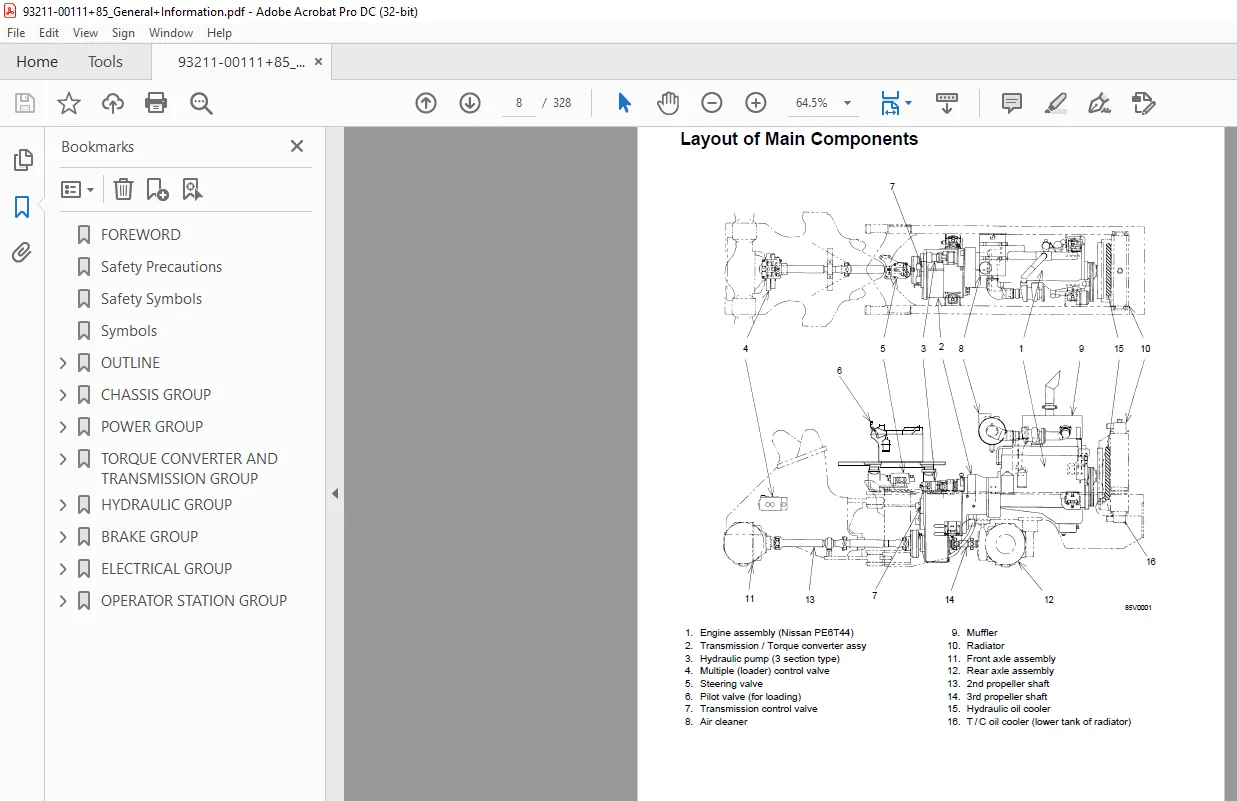
Layout of Main Components 8
Recommended Lubricants 9
Lubrication Chart 10
Weight of Main Components 11
Hexagon Bolt Tightening Torque 12
Flanged Hexagon Bolt Tightening Torque 14
Hose Band Tightening Torque 15
Liquid Gasket and Screw Lock Agent 16
Cautions Regarding Welding Repair Service 17
CHASSIS GROUP 19
Front Chassis 20
Loading system 20
Linkage 21
Rear Chassis 22
Fuel tank 22
Center Pin 23
Clearance Adjustment for Pin Section 24
Adjustment 24
Center Pin 25
Adjusting Shim(#5) 25
Installing bearing cover(#3) 25
Installing bearing outer ring(#9) 25
POWER GROUP 26
Outline of Power Line 27
Engine Mount 28
Radiator Mount 29
Propeller Shaft 30
Axle Assembly 32
Rear Axle Support 34
Differential Gear 36
Fuel Control 41
Engine Oil Pressure 42
Engine Compression Pressure 43
Engine Valve Clearance 44
Engine Fuel Injection Pressure 45
Engine Fuel Injection Timing 46
TORQUE CONVERTER AND TRANSMISSION GROUP 47
Torque Converter and Transmission 48
Construction 48
Gear Arrangement 49
Torque Converter Operation 50
Clutch Pack 51
Clutch Plate 53
Gear Pump 54
Power Flow 55
Hydraulic System Diagram 58
Hydraulic Circuit Diagram 59
Control Valve 60
Construction 60
System Diagram 61
Solenoid Valve Operation 62
Modulation Mechanism 65
Measuring Clutch Oil Pressure 70
HYDRAULIC GROUP 72
Loading/Steering Hydraulic Line 73
Loading/Steering Hydraulic System Diagram 74
Layout of Hydraulic Units 75
Hydraulic tank 76
Hydraulic Pump 80
Hydraulic Cylinder 82
Loading System 84
Pilot Valve 85
Pilot Valve Filter 89
Pilot Relief Valve Unit 90
Accumulator 92
Multiple Control Valve (KVML) 94
Adapter (with orifice) 103
Steering System 104
Steering Valve (KVMT) 106
Steering Gear Box 114
Emergency Steering 115
Standard Measurement Values for Performance Check 117
Cautions Regarding Replacement of Hydraulic Parts 118
Flushing Hydraulic Lines 119
Measuring Steering Wheel/Lever Operating Force 123
BRAKE GROUP 124
Brake and Air Circuit 125
Layout of Brake and Air Units 127
Air Governor 128
Air Tank 130
Brake Valve 135
Air Pressure Switch (for inching) 140
Double Check Valve 141
Air Master 142
Auto-adjuster Valve 145
Service Brake 148
Parking Brake 150
Solenoid Valve (for parking brake) 152
Air Cylinder 154
Brake Oil Tank 155
Checking Braking Performance 156
Checking Air Line Setting Pressure 156
Checking Brake Valve 157
Checking Air Master 159
Checking Wear of Service Brake Friction Plate 161
Adjusting Parking Brake Clearance 162
Brake Line Air Bleeding 163
ELECTRICAL GROUP 165
How to Use Electrical Wiring Diagram 167
Cable Color Codes 168
Electrical Wiring Diagram 169
Layout of Electrical Equipment 173
Electrical Connection Diagram 177
Layout of Electrical Equipment Inside Cab Control Box 179
Layout of Electrical Equipment Around Battery Relay 180
Fusible Link/Fuse 181
Engine Start Circuit 183
Alternator/Charge Circuit 190
Engine Stop Circuit 192
Transmission Control and Monitor Circuit 194
Instrument Panel 212
Electric Detent Circuit 216
Emergency Steering Circuit 218
Cautions Regarding Electric Circuit Check 219
Flow Chart for Troubleshooting of Electrical Transmission Control System 221
Judgment of Transmission Controller Abnormal Operation 222
On/Off Statuses of Transmission Controller LED Indicator 223
Function of Diagnostic System for Monitor Controller 227
Checking Shift Lever Input Circuit 234
Checking Inching(declutch)Input Circuit 236
Checking PUS Switch Input Circuit 238
Checking Speed Sensor Input Circuit 239
Checking Clutch Solenoid Valve Output Circuit 240
Checking Trimmer Plug Solenoid Valve 242
Checking Neutral Relay Circuit 244
Checking Parking Brake Circuit 245
Checking Engine Stop Circuit 246
Checking Gauge Circuit 249
OPERATOR STATION GROUP 252
ROPS Cabin 253
Floor Board 258
Steering and Transmission Shift Lever 265
Air Conditioner 273
Air conditioner mount 273
Air conditioner line routing 274
Structure 275
Air conditioner unit 275
Air damper unit 276
Air duct unit 277
Compressor (with magnetic clutch) 277
Condenser unit 278
Control unit 278
Control panel 278
Cooling mechanism 279
Principle of cooling 279
Refrigerant 279
Refrigerant characteristics 280
Electrical circuit diagram 282
Electrical wiring diagram 283
Functions of components 284
Control unit 284
Control panel 284
Control amplifier 286
Troubleshooting the control unit 286
Air conditioner unit 287
Air mixing damper 287
Evaporator 288
Troubleshooting the evaporator 288
Expansion valve (box type) 289
Operation of expansion valve (box type) 290
Troubleshooting the expansion valve 290
Heater radiator 291
Troubleshooting the heater radiator 291
Water valve 291
Troubleshooting the water valve 291
Actuator for air mixing 292
Troubleshooting the actuator for air mixing 292
Duct for vent selection 293
Actuator for vent selection 294
Troubleshooting the actuator for vent selec-tion 294
Blower motor assembly 295
Troubleshooting the blower motor 295
Blower resistor 295
Troubleshooting the blower resistor 295
Thermistor 296
Troubleshooting the thermistor 296
Air filter and air damper box 297
Air damper box 297
Actuator for inside/outside air selection 298
Troubleshooting the actuator for inside/out-side air selection 298
Air filter 299
Troubleshooting the air filter 299
Compressor and magnetic clutch 300
Compressor 300
Magnetic clutch 300
Troubleshooting the compressor and mag-netic clutch 301
Condenser unit 302
Condenser 302
Condenser fan motor 302
Resistor 302
Troubleshooting the condenser unit 302
Receiver dryer 303
Receiver tank 303
Desiccant 303
Troubleshooting the receiver tank 303
Strainers 303
Specifications 303
Access tube 304
Pressure switches 304
Troubleshooting the pressure switch 305
Sight glass 306
Relays 306
Relay A 307
Relay B 307
Troubleshooting the relay 307
Refrigerant hose 308
Charge of refrigerant 309
Evacuation and Charging Procedures 310
Work chart 310
Refrigerant charging tools 311
Refrigerant charging procedure 313
Troubleshooting using the gauge manifold 318
Adjustment of lubricating oil quantity 321
when components of air conditioner are replaced 321
When the compressor is replaced 322
When the evaporator is replaced 323
When the condenser is replaced 323
When the receiver dryer is replaced 323
Adjustment of water valve and air mixing dampers 324
Adjustment of air gap (between hub and rotor) in compressor magnet clutch 325
Adjustment of V belt in compressor 326
Parts to be replaced periodically 327
S.M 7/2/2025