Trusted Business
Verified & Licensed
Virus Free Files
100% Safe Downloads
Secure Payment
SSL Protected
Instant Delivery
Available Immediately
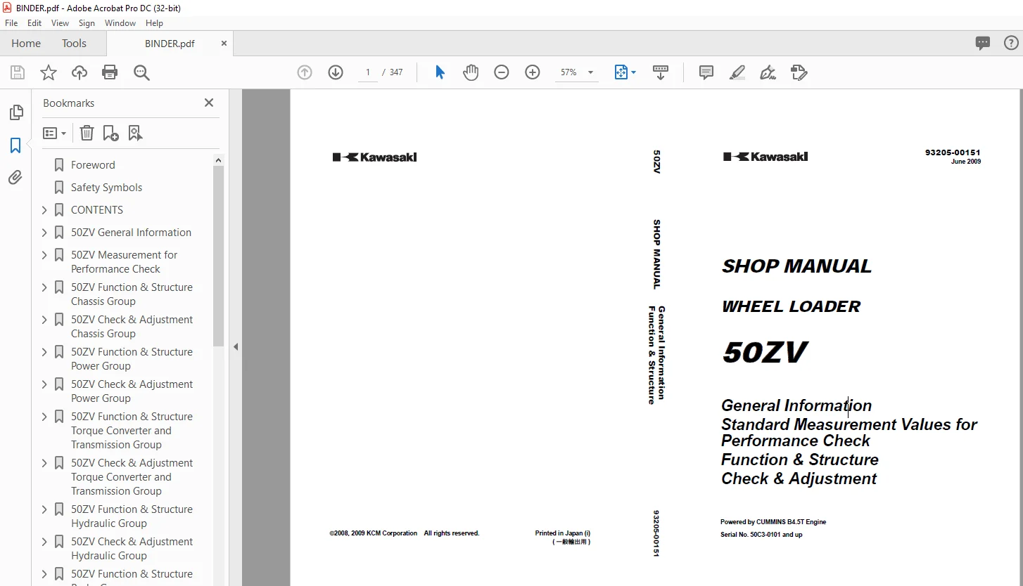
Kawasaki WHEEL LOADER 50ZV SHOP MANUAL 93205-00151 – PDF DOWNLOAD
$29.95
Kawasaki WHEEL LOADER 50ZV SHOP MANUAL 93205-00151 – PDF DOWNLOAD
General Information
Standard Measurement Values for Performance Check
Function & Structure Check & Adjustment
Standard Measurement Values for Performance Check
Function & Structure Check & Adjustment
Powered by CUMMINS B4.5T Engine
Serial No. 50C3-0101 and up
Instant PDF Download
Available immediately
Save to Your Device
Download & keep forever
Antivirus Scanned
100% virus-free
Trusted Worldwide
175,000+ customers
Description
Kawasaki WHEEL LOADER 50ZV SHOP MANUAL 93205-00151 – PDF DOWNLOAD
FILE DETAILS:
Kawasaki WHEEL LOADER 50ZV SHOP MANUAL 93205-00151 – PDF DOWNLOAD
Language :English
Pages :347
Downloadable : Yes
File Type : PDF
IMAGES PREVIEW OF THE MANUAL:
DESCRIPTION:
Kawasaki WHEEL LOADER 50ZV SHOP MANUAL 93205-00151 – PDF DOWNLOAD
General Information
Standard Measurement Values for Performance Check
Function & Structure Check & Adjustment
Standard Measurement Values for Performance Check
Function & Structure Check & Adjustment
Powered by CUMMINS B4.5T Engine
Serial No. 50C3-0101 and up
Foreword
- To ensure good machine performance, reduce failures or problems, and prolong the service life of
each component, it is necessary to operate the machine as is directed in the Operator and
Maintenance Manual. - To effectively diagnose and repair the machine, it is important to follow the guidelines laid out
in this Shop Manual.
General Information
Function and structure
- For the engine, refer to the engine Shop Manual provided by the engine manufacturer.
- The purpose of this manual is to provide information on the product and the correct maintenance and
repair meth- ods. Please read this manual to ensure correct troubleshooting and good repair
service. - This manual will be periodically reviewed and revised for more satisfactory content. If
you have any opinion or requests, please inform us.
TABLE OF CONTENTS:
Kawasaki WHEEL LOADER 50ZV SHOP MANUAL 93205-00151 – PDF DOWNLOAD
General Information
Standard Measurement Values for Performance Check
Function & Structure Check & Adjustment
Standard Measurement Values for Performance Check
Function & Structure Check & Adjustment
Powered by CUMMINS B4.5T Engine
Serial No. 50C3-0101 and up
Foreword 2
Safety Symbols 3
CONTENTS 4
50ZV General Information 00-1 4
How to Use Manual 00-2 4
Safety precautions 00-2 4
Symbols 00-3 4
Outline 00-4 4
Layout of main components 00-4 4
Inspection and maintenance table 00-5 4
Recommended lubricants 00-8 4
Coolant 00-10 4
Lubrication chart 00-11 4
Weight of main components 00-12 4
Bolt tightening torque 00-13 4
Hose band tightening torque 00-17 4
Liquid gasket and screw lock agent 00-18 4
Cautions regarding welding repair service 00-20 4
50ZV Measurement for Performance Check 03-1 4
Cautions on Safety 03-2 4
Standard Measurement Values for Performance Check 03-3 4
50ZV Function & Structure Chassis Group 12-1 4
Front Chassis 12-2 4
Loading linkage 12-2 4
Loading linkage pin 12-3 4
Rear Chassis 12-4 4
Fuel tank 12-4 4
Floor board mount 12-5 4
Center Pin 12-6 4
Upper center pin 12-6 4
Lower center pin 12-6 4
Dust seal 12-7 4
50ZV Check & Adjustment Chassis Group 13-1 4
Linkage Pin 13-2 4
Liner 13-2 4
Center Pin 13-4 4
Adjusting shim (#5) 13-4 4
Installing bearing cover (#3) 13-4 4
50ZV Function & Structure Power Group 22-1 5
Power Line 22-2 5
Engine / Transmission 22-3 5
Engine / transmission mount 22-3 5
Accelerator pedal 22-4 5
Fuel control 22-5 5
Radiator 22-6 5
Radiator mount 22-7 5
Propeller Shaft 22-8 5
Second propeller shaft assembly 22-9 5
Third propeller shaft assembly 22-10 5
Axle Assembly 22-11 5
Axle Support 22-12 5
Differential Gear 22-14 5
Function of TPD 22-15 5
Operation of TPD 22-16 5
50ZV Check & Adjustment Power Group 23-1 5
Engine 23-2 5
Measuring engine speed 23-2 5
Measuring engine oil pressure 23-2 5
Propeller Shaft 23-3 5
Propeller shaft phase 23-3 5
Second propeller shaft alignment 23-3 5
Tightening torque 23-4 5
Axle 23-5 5
Axle 23-5 5
Differential gear 23-6 5
50ZV Function & Structure Torque Converter and Transmission Group 32-1 5
Torque Converter 32-2 5
Torque converter structure 32-2 5
Power flow path 32-2 5
Torque multiplication 32-2 5
Torque Converter Gear Pump 32-3 5
Gear pump specifications 32-3 5
Transmission 32-4 6
Gear arrangement 32-4 6
Valve location 32-5 6
Clutch Pack 32-6 6
Forward and 2nd speed clutch 32-6 6
Reverse and 1st speed clutch 32-7 6
3rd speed clutch 32-8 6
Clutch specifications 32-8 6
Power Flow Path in the Transmission 32-9 6
Forward 32-9 6
Reverse 32-10 6
Hydraulic System Diagram 32-11 6
Hydraulic Circuit Diagram 32-12 6
Oil Flow 32-13 6
Oil flow in the torque converter line 32-13 6
Oil flow to the clutch 32-13 6
Shift Lever 32-14 6
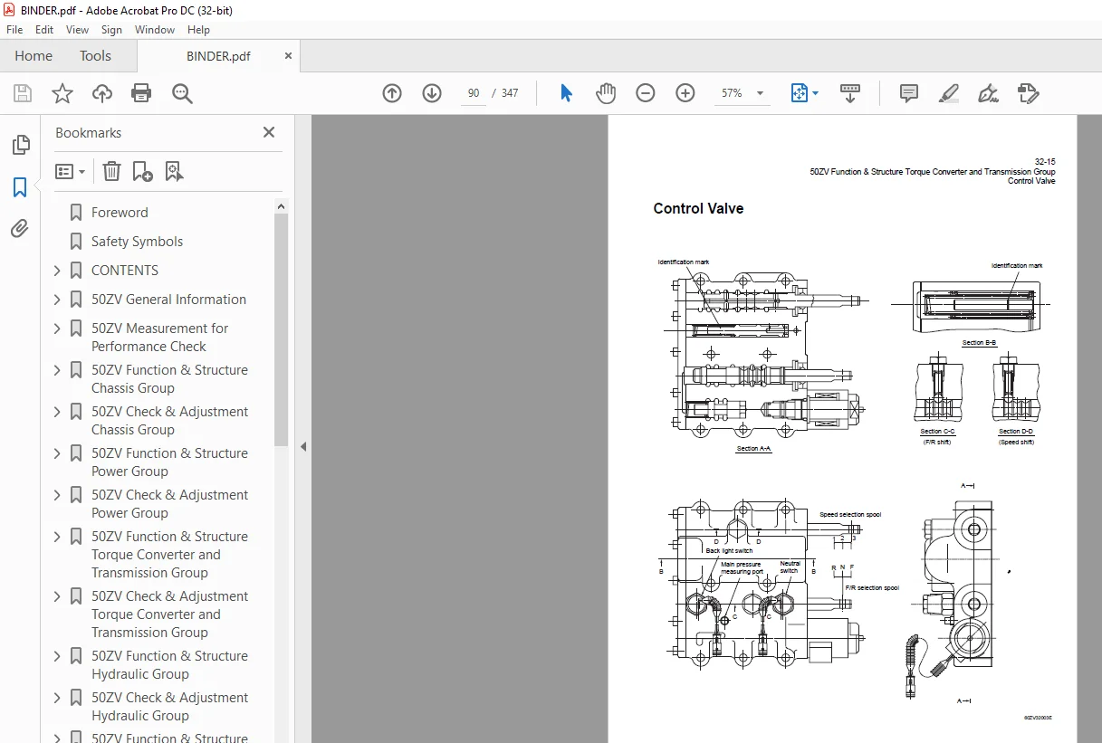
Control Valve 32-15 6
System diagram 32-16 6
Oil port layout 32-17 6
Modulation Mechanism 32-19 6
Clutch control oil pressure curve 32-19 6
Before the shift lever is moved (travelling or stop condition) 32-20 6
When the shift lever is moved (1) 32-21 6
When the shift lever is moved (2) 32-22 6
Accumulator 32-23 6
Accumulator for 1st speed clutch 32-23 6
Solenoid Valve 32-25 6
Clutch cut-off solenoid valve 32-25 6
50ZV Check & Adjustment Torque Converter and Transmission Group 33-1 6
Clutch Oil Pressure 33-2 6
50ZV Function & Structure Hydraulic Group 42-1 6
Flushing Hydraulic Circuit 42-2 6
Purpose of flushing 42-2 6
Cautions on Hydraulic Parts Replacement 42-3 6
Hydraulic Circuit Symbols 42-4 7
Hydraulic lines 42-4 7
Pumps & motors 42-4 7
Cylinders 42-4 7
Operation methods 42-5 7
Pressure control valve 42-5 7
Flow control valve 42-5 7
Directional control valve 42-6 7
Check valve 42-6 7
Miscellaneous hydraulic symbols 42-7 7
Hydraulic System Operation 42-8 7
Hydraulic system operation outline 42-8 7
Layout of Hydraulic Units 42-9 7
Hydraulic Tank 42-10 7
Hydraulic tank breather valve (tank cap) 42-11 7
Hydraulic tank specifications 42-12 7
Hydraulic oil level check 42-12 7
Hydraulic Pump 42-13 7
Hydraulic pump specifications 42-13 7
Hydraulic pump principle 42-14 7
Hydraulic pump wear plate 42-15 7
Hydraulic pump bushing lubrication 42-15 7
Hydraulic Cylinder 42-16 7
Boom cylinder 42-16 7
Bucket cylinder 42-17 7
Steering cylinder 42-17 7
Hydraulic cylinder specifications 42-18 7
Return Filter 42-19 7
Return filter specifications 42-19 7
Loading System 42-20 7
Multiple Control Valve 42-21 8
Multiple control valve specifications 42-23 8
Multiple control valve main relief valve 42-24 8
Multiple control valve overload relief valve (with make-up function) 42-26 8
Multiple control valve make-up valve 42-28 8
Multiple control valve bucket spool 42-29 8
Multiple control valve boom spool 42-31 8
Valve Control 42-34 8
Steering System 42-35 8
Priority Valve 42-37 8
Priority valve specifications 42-37 8
Priority valve operation 42-38 8
Orbitrol® 42-41 8
Orbitrol® construction 42-41 8
Orbitrol® specification 42-42 8
Orbitrol® operation 42-43 8
Orbitrol® feed-back mechanism operation 42-45 8
Steering speed and flow rate control 42-46 8
Hydraulic pump oil amount and steering force 42-46 8
Orbit rotor operation principle 42-47 8
Auxiliary valves 42-48 8
Emergency check valve 42-50 8
Inlet check valve 42-50 8
Cushion Valve 42-51 8
Cushion valve specifications 42-52 8
Cushion valve operation 42-52 8
50ZV Check & Adjustment Hydraulic Group 43-1 8
Loading/Steering Circuit Relief Valve 43-2 8
Loading circuit relief valve setting pressures 43-2 8
Steering circuit relief valve setting pressures 43-6 8
Valve Control 43-9 8
Hydraulic Cylinder 43-10 8
Cylinder natural drift 43-10 8
50ZV Function & Structure Brake Group 52-1 8
Brake Units Layout 52-2 8
Brake Circuit 52-3 9
Hydraulic Servo Master Cylinder 52-4 9
Hydraulic servo master cylinder specifications 52-5 9
Performance diagram 52-5 9
Hydraulic servo master cylinder operation 52-6 9
Service Brake 52-8 9
Service brake operation 52-8 9
Service brake friction plate 52-9 9
Service brake steel plate 52-9 9
Brake circuit air bleeding procedure 52-10 9
Parking Brake 52-12 9
Brake Control 52-13 9
Service brake linkage 52-13 9
Parking brake linkage 52-14 9
Brake Oil Reservoir 52-15 9
Brake oil reservoir specifications 52-15 9
50ZV Check & Adjustment Brake Group 53-1 9
Hydraulic Servo Master 53-2 9
Hydraulic servo master performance inspection 53-2 9
Service Brake 53-4 9
Service brake performance check 53-4 9
Service brake friction plate wear measurement 53-5 9
Parking Brake 53-6 9
Parking brake performance check 53-6 9
Parking brake clearance adjustment 53-7 9
Brake Control 53-9 9
Adjusting brake pedal and switch 53-9 9
Parking brake cable adjustment 53-11 9
50ZV Function & Structure Electrical Group 62-1 9
How to Use Electrical Wiring Diagram 62-2 9
Electrical Cable Color Codes 62-3 9
Electrical Circuit Symbols 62-4 9
Sensor Mount 62-5 9
Fuse 62-6 10
Fuse box 62-6 10
Fusible link 62-7 10
Engine Start Circuit 62-8 10
Engine start circuit diagram 62-8 10
Neutral starter 62-9 10
Starter switch 62-10 10
Battery relay 62-11 10
Alternator R terminal wire 62-12 10
Diode unit 62-12 10
Neutral switch 62-13 10
Magnet switch 62-14 10
Voltage relay 62-15 10
Power Generating/Charging Circuit 62-16 10
Alternator 62-16 10
Engine Stop Circuit 62-18 10
Fuel solenoid 62-18 10
Fuel solenoid relay 62-18 10
Instrument Panel and Switch 62-19 10
Instrument panel 62-19 10
Instrument panel rear surface 62-20 10
Gauge circuit 62-21 10
Fuel level sensor 62-23 10
Monitoring system 62-24 10
Transmission Electrical Circuit 62-27 10
Transmission cut off (Declutch) switch 62-27 10
Inching switch 62-28 10
Solenoid valve 62-28 10
Electrical Detent Circuit 62-29 10
Bucket detent 62-29 10
Diode Unit Circuit 62-31 10
Diode inspection 62-31 10
Stop Light Switch Circuit 62-34 10
Parking Switch 62-35 10
Back-up Light Switch Circuit 62-36 10
Horn Circuit 62-37 11
Diode 62-38 11
Diode check method 62-39 11
Caution for diode check method 62-39 11
Surge voltage and surge suppression diodes 62-41 11
50ZV Check & Adjustment Electrical Group 63-1 11
Cautions Regarding Electric Circuit Check 63-2 11
Disconnecting or reinstalling connector 63-2 11
How to attach the probes of the circuit tester 63-4 11
Electrical Circuit Check 63-5 11
Transmission control circuit check 63-5 11
Bucket positioner electrical circuit check 63-6 11
Diode unit circuit check 63-7 11
Gauge circuit electrical circuit check 63-8 11
50ZV Function & Structure Operator Station Group 72-1 11
Cabin (OPT) 72-2 11
Cabin connection diagram 72-3 11
Wiper motor 72-4 11
Operator Seat 72-6 11
Seat assembly 72-6 11
Suspension assembly 72-7 11
Air Conditioner (OPT) 72-8 11
Air conditioner mount 72-8 11
Air conditioner line 72-9 11
Air conditioner structure 72-10 11
Function of cooling mechanism 72-15 11
Cooling circuit 72-18 11
Air conditioner function of components 72-19 11
Charge of refrigerant 72-47 11
50ZV Check & Adjustment Operator Station Group 73-1 12
Air Conditioner 73-2 12
Adjustment of lubricating oil quantity when components of air conditioner are replaced 73-2 12
Water valve and air mix damper adjustment 73-5 12
Adjustment of air gap (between hub and rotor) in compressor magnetic clutch 73-6 12
Compressor V-belt adjustment 73-7 12
Parts to be replaced periodically 73-8 12
50ZV Drawing & Diagrams 92-1 12
Axle Assembly 92-2 12
Torque Converter and Transmission 92-3 12
Loading/Steering Hydraulic Line 92-4 12
Brake Circuit 92-5 12
Electrical Wiring Diagram (1/2) 92-6 12
Electrical Wiring Diagram (2/2) 92-7 12
Electrical Connection Diagram 92-8 12
Electrical Wiring Diagram (CAB) 92-9 12
Electrical Equipment Layout 92-10 12
Electrical Circuit Diagram (Cabin Air Conditioner) 92-14 12
Electrical Wiring Diagram (Cabin Air Conditioner) 92-15 12
50ZV General Information 14
How to Use Manual 15
Safety precautions 15
Symbols 16
Outline 17
Layout of main components 17
Inspection and maintenance table 18
Recommended lubricants 21
Coolant 23
Coolant specification 23
Recommended mixture of antifreeze 23
Lubrication chart 24
Weight of main components 25
Bolt tightening torque 26
Hexagon bolt 26
Flanged hexagon bolt 29
Hose band tightening torque 30
Liquid gasket and screw lock agent 31
Cautions regarding parts removal 31
Cautions regarding reassembly 31
Screw lock agent application procedure 32
How to wind a seal tape 32
Cautions regarding welding repair service 33
Cautions 33
MEMO 35
50ZV Measurement for Performance Check 36
Cautions on Safety 37
Standard Measurement Values for Performance Check 38
50ZV Function & Structure Chassis Group 40
Front Chassis 41
Loading linkage 41
Loading linkage pin 42
Rear Chassis 43
Fuel tank 43
Floor board mount 44
Floor board 44
Viscous mount 44
Center Pin 45
Upper center pin 45
Lower center pin 45
Dust seal 46
MEMO 47
50ZV Check & Adjustment Chassis Group 48
Linkage Pin 49
Liner 49
Adjustment 50
Center Pin 51
Adjusting shim (#5) 51
Installing bearing cover (#3) 51
50ZV Function & Structure Power Group 52
Power Line 53
Engine / Transmission 54
Engine / transmission mount 54
Accelerator pedal 55
Fuel control 56
Radiator 57
Radiator mount 58
Propeller Shaft 59
Second propeller shaft assembly 60
Front differential – Transmission 60
Third propeller shaft assembly 61
Transmission – Rear differential 61
Axle Assembly 62
Axle Support 63
Differential Gear 65
Function of TPD 66
Difference in gear shapes 66
Contact between pinion and side gear 66
Operation of TPD 67
50ZV Check & Adjustment Power Group 68
Engine 69
Measuring engine speed 69
Measurement instrument 69
Standard measurement value 69
Measuring engine oil pressure 69
Measurement instrument 69
Install position 69
Standard measurement value 69
Propeller Shaft 70
Propeller shaft phase 70
Second propeller shaft alignment 70
Tightening torque 71
Axle 72
Axle 72
Differential gear 73
Adjusting tooth contact 74
50ZV Function & Structure Torque Converter and Transmission Group 76
Torque Converter 77
Torque converter structure 77
Power flow path 77
Torque multiplication 77
Torque Converter Gear Pump 78
Gear pump specifications 78
Transmission 79
Gear arrangement 79
Valve location 80
Clutch Pack 81
Forward and 2nd speed clutch 81
Reverse and 1st speed clutch 82
3rd speed clutch 83
Clutch specifications 83
Power Flow Path in the Transmission 84
Forward 84
Forward 1st speed 84
Forward 2nd speed 84
Forward 3rd speed 85
Reverse 85
Reverse 1st speed 85
Reverse 2nd and 3rd speeds 85
Hydraulic System Diagram 86
Hydraulic Circuit Diagram 87
Oil Flow 88
Oil flow in the torque converter line 88
From the torque converter pump to torque converter 88
From torque converter to cooling circuit 88
From cooler to lubrication circuit 88
Oil flow to the clutch 88
To forward and reverse clutches 88
To speed clutches 88
Shift Lever 89
Forward/Reverse selection 89
Speed selection 89
Control Valve 90
System diagram 91
Oil port layout 92
Control valve 92
Sub-plate 93
Modulation Mechanism 94
Clutch control oil pressure curve 94
Before the shift lever is moved (travelling or stop condition) 95
High pressure holding 95
When the shift lever is moved (1) 96
Initial oil feeding to clutch piston chamber 96
When the shift lever is moved (2) 97
Pressure increase 97
Accumulator 98
Accumulator for 1st speed clutch 98
Before shifting to 1st speed 98
During shifting to 1st speed (A) 98
During shifting to 1st speed (B) 99
When shifting to 1st speed is completed 99
Solenoid Valve100
Clutch cut-off solenoid valve100
Clutch cut-off solenoid valve operation100
MEMO101
50ZV Check & Adjustment Torque Converter and Transmission Group102
Clutch Oil Pressure103
50ZV Function & Structure Hydraulic Group104
Flushing Hydraulic Circuit105
Purpose of flushing105
Cautions on Hydraulic Parts Replacement106
Hydraulic Circuit Symbols107
Hydraulic lines107
Pumps & motors107
Cylinders107
Operation methods108
Pressure control valve108
Flow control valve108
Directional control valve109
Check valve109
Miscellaneous hydraulic symbols110
Hydraulic System Operation111
Hydraulic system operation outline111
Loading system111
Steering system111
Layout of Hydraulic Units112
Hydraulic Tank113
Hydraulic tank breather valve (tank cap)114
Hydraulic tank specifications115
Hydraulic oil level check115
Hydraulic Pump116
Hydraulic pump specifications116
Hydraulic pump principle117
Hydraulic pump wear plate118
Hydraulic pump bushing lubrication118
Hydraulic Cylinder119
Boom cylinder119
Bucket cylinder120
Steering cylinder120
Hydraulic cylinder specifications121
Return Filter122
Return filter specifications122
Loading System123
Multiple Control Valve124
Multiple control valve specifications126
Multiple control valve main relief valve127
Main relief valve operation127
Adjusting set pressure128
Multiple control valve overload relief valve (with make-up function)129
Overload relief valve operation129
Adjusting set pressure130
Multiple control valve make-up valve131
Make-up valve operation131
Multiple control valve bucket spool132
Bucket spool operation132
Multiple control valve boom spool134
Boom spool operation134
Valve Control137
Steering System138
Priority Valve140
Priority valve specifications140
Priority valve operation141
Relief valve operation143
Orbitrol®144
Orbitrol® construction144
Valve part144
Rotor part145
Orbitrol® specification145
Orbitrol® operation146
Neutral146
Turn147
Orbitrol® feed-back mechanism operation148
Steering speed and flow rate control149
Hydraulic pump oil amount and steering force149
Orbit rotor operation principle150
Auxiliary valves151
Overload relief valve and make-up valve152
Emergency check valve153
Inlet check valve153
Cushion Valve154
Cushion valve specifications155
Cushion valve operation155
50ZV Check & Adjustment Hydraulic Group156
Loading/Steering Circuit Relief Valve157
Loading circuit relief valve setting pressures157
Measurement instruments157
Gauge port157
Standard measurement value MPa (kgf/cm2) (psi)158
Measuring loading circuit main relief pressure158
Measuring loading circuit overload relief pressure159
Steering circuit relief valve setting pressures161
Measurement instruments161
Gauge port161
Standard measurement value MPa (kgf/cm2) (psi)161
Measuring steering circuit main relief pressure162
Measuring steering circuit overload relief pressure163
Valve Control164
Hydraulic Cylinder165
Cylinder natural drift165
Measurement instrument165
Standard measurement value (mm/min) (in/min)165
Measurement procedure165
MEMO167
50ZV Function & Structure Brake Group168
Brake Units Layout169
Brake Circuit170
Hydraulic Servo Master Cylinder171
Hydraulic servo master cylinder specifications172
Performance diagram172
Hydraulic servo master cylinder operation173
No braking (when the brake is released)173
Braking173
When the brake is in the hold (balanced) position174
When the pedal is depressed a second time174
Braking in case of one brake system failing174
Braking in case of pump failure174
Service Brake175
Service brake operation175
Service brake friction plate176
Service brake steel plate176
Brake circuit air bleeding procedure177
Parking Brake179
Brake Control180
Service brake linkage180
Parking brake linkage181
Brake Oil Reservoir182
Brake oil reservoir specifications182
MEMO183
50ZV Check & Adjustment Brake Group184
Hydraulic Servo Master185
Hydraulic servo master performance inspection185
Service Brake187
Service brake performance check187
Condition187
Standard measurement value187
Service brake friction plate wear measurement188
Parking Brake189
Parking brake performance check189
Condition189
Standard measurement value189
Parking brake clearance adjustment190
Adjustment procedure190
Brake lining abrasion check191
Brake Control192
Adjusting brake pedal and switch192
Adjusting right brake pedal192
Adjusting left brake pedal193
Adjusting switch194
Parking brake cable adjustment194
50ZV Function & Structure Electrical Group196
How to Use Electrical Wiring Diagram197
Electrical Cable Color Codes198
Electrical Circuit Symbols199
Sensor Mount200
Fuse201
Fuse box201
Fusible link202
Engine Start Circuit203
Engine start circuit diagram203
Neutral starter204
Shift lever neutral (N) position204
Shift lever forward/reverse (F/R) position204
Starter switch205
Battery relay206
Battery relay operation206
Alternator R terminal wire207
Diode unit207
Neutral switch208
Neutral switch operation208
Neutral switch specifications208
Magnet switch209
Voltage relay210
Power Generating/Charging Circuit211
Alternator211
Alternator generation theory212
Engine Stop Circuit213
Fuel solenoid213
Fuel solenoid specification213
Fuel solenoid relay213
Instrument Panel and Switch214
Instrument panel214
Instrument panel rear surface215
Gauge circuit216
Fuel level sensor218
Monitoring system219
Items to be monitored and operation condition220
Operation monitor lamps221
Transmission Electrical Circuit222
Transmission cut off (Declutch) switch222
Inching switch223
Clutch cut-off circuit223
Solenoid valve223
Solenoid valve specification223
Solenoid valve operation table223
Electrical Detent Circuit224
Bucket detent224
Bucket positioner224
Boom kick-out unit (optional)224
Proximity switch225
Diode Unit Circuit226
Diode inspection226
Stop Light Switch Circuit229
Parking Switch230
Back-up Light Switch Circuit231
Horn Circuit232
Horn relay232
Diode233
Diode check method234
Caution for diode check method234
Continuity check mode234
Diode check mode234
Resistance check mode235
Surge voltage and surge suppression diodes236
MEMO237
50ZV Check & Adjustment Electrical Group238
Cautions Regarding Electric Circuit Check239
Disconnecting or reinstalling connector239
How to attach the probes of the circuit tester241
Electrical Circuit Check242
Transmission control circuit check242
Bucket positioner electrical circuit check243
Diode unit circuit check244
Gauge circuit electrical circuit check245
MEMO247
50ZV Function & Structure Operator Station Group248
Cabin (OPT)249
Cabin connection diagram250
Wiper motor251
Operator Seat253
Seat assembly253
Reclining seat adjustment253
Suspension assembly254
Suspension adjustment254
Air Conditioner (OPT)255
Air conditioner mount255
Air conditioner specifications255
Air conditioner line256
Air conditioner structure257
Air conditioner unit257
Air damper unit258
Air duct unit259
Compressor (with magnetic clutch)259
Condenser unit260
Control unit261
Function of cooling mechanism262
Principle of cooling262
Refrigerant263
Refrigerant characteristics264
Cooling circuit265
Air conditioner function of components266
Control unit266
Air conditioner unit269
Air filters and air damper box280
Compressor and magnetic clutch283
Condenser unit286
Receiver dryer288
Sight glass290
Pressure switches290
Pressure relief valve291
Relay A292
Relay B292
Refrigerant hose293
Charge of refrigerant294
Work procedure295
Refrigerant charging tools297
Refrigerant charging procedure300
Troubleshooting using the gauge manifold306
MEMO311
50ZV Check & Adjustment Operator Station Group312
Air Conditioner313
Adjustment of lubricating oil quantity when components of air conditioner are replaced313
When the compressor is replaced314
When the evaporator is replaced315
When the condenser is replaced315
Water valve and air mix damper adjustment316
Water valve adjustment316
Air mix damper B adjustment316
Adjustment of air gap (between hub and rotor) in compressor magnetic clutch317
Compressor V-belt adjustment318
Belt adjustment value318
Parts to be replaced periodically319
Air filters319
Receiver dryer319
INDEX320
A320
B320
C320
D320
E321
F321
G321
H321
I321
L322
M322
N322
O322
P322
R322
S323
T323
U323
V323
W323
MEMO324
Maintenance Log325
Notes329
50ZV Drawing & Diagrams333
Axle Assembly334
Torque Converter and Transmission335
Loading/Steering Hydraulic Line336
Brake Circuit337
Electrical Wiring Diagram (1/2)338
Electrical Wiring Diagram (2/2)339
Electrical Connection Diagram340
Electrical Wiring Diagram (CAB)341
Electrical Equipment Layout342
Electrical Circuit Diagram (Cabin Air Conditioner)346
Electrical Wiring Diagram (Cabin Air Conditioner)347
Safety Symbols 3
CONTENTS 4
50ZV General Information 00-1 4
How to Use Manual 00-2 4
Safety precautions 00-2 4
Symbols 00-3 4
Outline 00-4 4
Layout of main components 00-4 4
Inspection and maintenance table 00-5 4
Recommended lubricants 00-8 4
Coolant 00-10 4
Lubrication chart 00-11 4
Weight of main components 00-12 4
Bolt tightening torque 00-13 4
Hose band tightening torque 00-17 4
Liquid gasket and screw lock agent 00-18 4
Cautions regarding welding repair service 00-20 4
50ZV Measurement for Performance Check 03-1 4
Cautions on Safety 03-2 4
Standard Measurement Values for Performance Check 03-3 4
50ZV Function & Structure Chassis Group 12-1 4
Front Chassis 12-2 4
Loading linkage 12-2 4
Loading linkage pin 12-3 4
Rear Chassis 12-4 4
Fuel tank 12-4 4
Floor board mount 12-5 4
Center Pin 12-6 4
Upper center pin 12-6 4
Lower center pin 12-6 4
Dust seal 12-7 4
50ZV Check & Adjustment Chassis Group 13-1 4
Linkage Pin 13-2 4
Liner 13-2 4
Center Pin 13-4 4
Adjusting shim (#5) 13-4 4
Installing bearing cover (#3) 13-4 4
50ZV Function & Structure Power Group 22-1 5
Power Line 22-2 5
Engine / Transmission 22-3 5
Engine / transmission mount 22-3 5
Accelerator pedal 22-4 5
Fuel control 22-5 5
Radiator 22-6 5
Radiator mount 22-7 5
Propeller Shaft 22-8 5
Second propeller shaft assembly 22-9 5
Third propeller shaft assembly 22-10 5
Axle Assembly 22-11 5
Axle Support 22-12 5
Differential Gear 22-14 5
Function of TPD 22-15 5
Operation of TPD 22-16 5
50ZV Check & Adjustment Power Group 23-1 5
Engine 23-2 5
Measuring engine speed 23-2 5
Measuring engine oil pressure 23-2 5
Propeller Shaft 23-3 5
Propeller shaft phase 23-3 5
Second propeller shaft alignment 23-3 5
Tightening torque 23-4 5
Axle 23-5 5
Axle 23-5 5
Differential gear 23-6 5
50ZV Function & Structure Torque Converter and Transmission Group 32-1 5
Torque Converter 32-2 5
Torque converter structure 32-2 5
Power flow path 32-2 5
Torque multiplication 32-2 5
Torque Converter Gear Pump 32-3 5
Gear pump specifications 32-3 5
Transmission 32-4 6
Gear arrangement 32-4 6
Valve location 32-5 6
Clutch Pack 32-6 6
Forward and 2nd speed clutch 32-6 6
Reverse and 1st speed clutch 32-7 6
3rd speed clutch 32-8 6
Clutch specifications 32-8 6
Power Flow Path in the Transmission 32-9 6
Forward 32-9 6
Reverse 32-10 6
Hydraulic System Diagram 32-11 6
Hydraulic Circuit Diagram 32-12 6
Oil Flow 32-13 6
Oil flow in the torque converter line 32-13 6
Oil flow to the clutch 32-13 6
Shift Lever 32-14 6
Control Valve 32-15 6
System diagram 32-16 6
Oil port layout 32-17 6
Modulation Mechanism 32-19 6
Clutch control oil pressure curve 32-19 6
Before the shift lever is moved (travelling or stop condition) 32-20 6
When the shift lever is moved (1) 32-21 6
When the shift lever is moved (2) 32-22 6
Accumulator 32-23 6
Accumulator for 1st speed clutch 32-23 6
Solenoid Valve 32-25 6
Clutch cut-off solenoid valve 32-25 6
50ZV Check & Adjustment Torque Converter and Transmission Group 33-1 6
Clutch Oil Pressure 33-2 6
50ZV Function & Structure Hydraulic Group 42-1 6
Flushing Hydraulic Circuit 42-2 6
Purpose of flushing 42-2 6
Cautions on Hydraulic Parts Replacement 42-3 6
Hydraulic Circuit Symbols 42-4 7
Hydraulic lines 42-4 7
Pumps & motors 42-4 7
Cylinders 42-4 7
Operation methods 42-5 7
Pressure control valve 42-5 7
Flow control valve 42-5 7
Directional control valve 42-6 7
Check valve 42-6 7
Miscellaneous hydraulic symbols 42-7 7
Hydraulic System Operation 42-8 7
Hydraulic system operation outline 42-8 7
Layout of Hydraulic Units 42-9 7
Hydraulic Tank 42-10 7
Hydraulic tank breather valve (tank cap) 42-11 7
Hydraulic tank specifications 42-12 7
Hydraulic oil level check 42-12 7
Hydraulic Pump 42-13 7
Hydraulic pump specifications 42-13 7
Hydraulic pump principle 42-14 7
Hydraulic pump wear plate 42-15 7
Hydraulic pump bushing lubrication 42-15 7
Hydraulic Cylinder 42-16 7
Boom cylinder 42-16 7
Bucket cylinder 42-17 7
Steering cylinder 42-17 7
Hydraulic cylinder specifications 42-18 7
Return Filter 42-19 7
Return filter specifications 42-19 7
Loading System 42-20 7
Multiple Control Valve 42-21 8
Multiple control valve specifications 42-23 8
Multiple control valve main relief valve 42-24 8
Multiple control valve overload relief valve (with make-up function) 42-26 8
Multiple control valve make-up valve 42-28 8
Multiple control valve bucket spool 42-29 8
Multiple control valve boom spool 42-31 8
Valve Control 42-34 8
Steering System 42-35 8
Priority Valve 42-37 8
Priority valve specifications 42-37 8
Priority valve operation 42-38 8
Orbitrol® 42-41 8
Orbitrol® construction 42-41 8
Orbitrol® specification 42-42 8
Orbitrol® operation 42-43 8
Orbitrol® feed-back mechanism operation 42-45 8
Steering speed and flow rate control 42-46 8
Hydraulic pump oil amount and steering force 42-46 8
Orbit rotor operation principle 42-47 8
Auxiliary valves 42-48 8
Emergency check valve 42-50 8
Inlet check valve 42-50 8
Cushion Valve 42-51 8
Cushion valve specifications 42-52 8
Cushion valve operation 42-52 8
50ZV Check & Adjustment Hydraulic Group 43-1 8
Loading/Steering Circuit Relief Valve 43-2 8
Loading circuit relief valve setting pressures 43-2 8
Steering circuit relief valve setting pressures 43-6 8
Valve Control 43-9 8
Hydraulic Cylinder 43-10 8
Cylinder natural drift 43-10 8
50ZV Function & Structure Brake Group 52-1 8
Brake Units Layout 52-2 8
Brake Circuit 52-3 9
Hydraulic Servo Master Cylinder 52-4 9
Hydraulic servo master cylinder specifications 52-5 9
Performance diagram 52-5 9
Hydraulic servo master cylinder operation 52-6 9
Service Brake 52-8 9
Service brake operation 52-8 9
Service brake friction plate 52-9 9
Service brake steel plate 52-9 9
Brake circuit air bleeding procedure 52-10 9
Parking Brake 52-12 9
Brake Control 52-13 9
Service brake linkage 52-13 9
Parking brake linkage 52-14 9
Brake Oil Reservoir 52-15 9
Brake oil reservoir specifications 52-15 9
50ZV Check & Adjustment Brake Group 53-1 9
Hydraulic Servo Master 53-2 9
Hydraulic servo master performance inspection 53-2 9
Service Brake 53-4 9
Service brake performance check 53-4 9
Service brake friction plate wear measurement 53-5 9
Parking Brake 53-6 9
Parking brake performance check 53-6 9
Parking brake clearance adjustment 53-7 9
Brake Control 53-9 9
Adjusting brake pedal and switch 53-9 9
Parking brake cable adjustment 53-11 9
50ZV Function & Structure Electrical Group 62-1 9
How to Use Electrical Wiring Diagram 62-2 9
Electrical Cable Color Codes 62-3 9
Electrical Circuit Symbols 62-4 9
Sensor Mount 62-5 9
Fuse 62-6 10
Fuse box 62-6 10
Fusible link 62-7 10
Engine Start Circuit 62-8 10
Engine start circuit diagram 62-8 10
Neutral starter 62-9 10
Starter switch 62-10 10
Battery relay 62-11 10
Alternator R terminal wire 62-12 10
Diode unit 62-12 10
Neutral switch 62-13 10
Magnet switch 62-14 10
Voltage relay 62-15 10
Power Generating/Charging Circuit 62-16 10
Alternator 62-16 10
Engine Stop Circuit 62-18 10
Fuel solenoid 62-18 10
Fuel solenoid relay 62-18 10
Instrument Panel and Switch 62-19 10
Instrument panel 62-19 10
Instrument panel rear surface 62-20 10
Gauge circuit 62-21 10
Fuel level sensor 62-23 10
Monitoring system 62-24 10
Transmission Electrical Circuit 62-27 10
Transmission cut off (Declutch) switch 62-27 10
Inching switch 62-28 10
Solenoid valve 62-28 10
Electrical Detent Circuit 62-29 10
Bucket detent 62-29 10
Diode Unit Circuit 62-31 10
Diode inspection 62-31 10
Stop Light Switch Circuit 62-34 10
Parking Switch 62-35 10
Back-up Light Switch Circuit 62-36 10
Horn Circuit 62-37 11
Diode 62-38 11
Diode check method 62-39 11
Caution for diode check method 62-39 11
Surge voltage and surge suppression diodes 62-41 11
50ZV Check & Adjustment Electrical Group 63-1 11
Cautions Regarding Electric Circuit Check 63-2 11
Disconnecting or reinstalling connector 63-2 11
How to attach the probes of the circuit tester 63-4 11
Electrical Circuit Check 63-5 11
Transmission control circuit check 63-5 11
Bucket positioner electrical circuit check 63-6 11
Diode unit circuit check 63-7 11
Gauge circuit electrical circuit check 63-8 11
50ZV Function & Structure Operator Station Group 72-1 11
Cabin (OPT) 72-2 11
Cabin connection diagram 72-3 11
Wiper motor 72-4 11
Operator Seat 72-6 11
Seat assembly 72-6 11
Suspension assembly 72-7 11
Air Conditioner (OPT) 72-8 11
Air conditioner mount 72-8 11
Air conditioner line 72-9 11
Air conditioner structure 72-10 11
Function of cooling mechanism 72-15 11
Cooling circuit 72-18 11
Air conditioner function of components 72-19 11
Charge of refrigerant 72-47 11
50ZV Check & Adjustment Operator Station Group 73-1 12
Air Conditioner 73-2 12
Adjustment of lubricating oil quantity when components of air conditioner are replaced 73-2 12
Water valve and air mix damper adjustment 73-5 12
Adjustment of air gap (between hub and rotor) in compressor magnetic clutch 73-6 12
Compressor V-belt adjustment 73-7 12
Parts to be replaced periodically 73-8 12
50ZV Drawing & Diagrams 92-1 12
Axle Assembly 92-2 12
Torque Converter and Transmission 92-3 12
Loading/Steering Hydraulic Line 92-4 12
Brake Circuit 92-5 12
Electrical Wiring Diagram (1/2) 92-6 12
Electrical Wiring Diagram (2/2) 92-7 12
Electrical Connection Diagram 92-8 12
Electrical Wiring Diagram (CAB) 92-9 12
Electrical Equipment Layout 92-10 12
Electrical Circuit Diagram (Cabin Air Conditioner) 92-14 12
Electrical Wiring Diagram (Cabin Air Conditioner) 92-15 12
50ZV General Information 14
How to Use Manual 15
Safety precautions 15
Symbols 16
Outline 17
Layout of main components 17
Inspection and maintenance table 18
Recommended lubricants 21
Coolant 23
Coolant specification 23
Recommended mixture of antifreeze 23
Lubrication chart 24
Weight of main components 25
Bolt tightening torque 26
Hexagon bolt 26
Flanged hexagon bolt 29
Hose band tightening torque 30
Liquid gasket and screw lock agent 31
Cautions regarding parts removal 31
Cautions regarding reassembly 31
Screw lock agent application procedure 32
How to wind a seal tape 32
Cautions regarding welding repair service 33
Cautions 33
MEMO 35
50ZV Measurement for Performance Check 36
Cautions on Safety 37
Standard Measurement Values for Performance Check 38
50ZV Function & Structure Chassis Group 40
Front Chassis 41
Loading linkage 41
Loading linkage pin 42
Rear Chassis 43
Fuel tank 43
Floor board mount 44
Floor board 44
Viscous mount 44
Center Pin 45
Upper center pin 45
Lower center pin 45
Dust seal 46
MEMO 47
50ZV Check & Adjustment Chassis Group 48
Linkage Pin 49
Liner 49
Adjustment 50
Center Pin 51
Adjusting shim (#5) 51
Installing bearing cover (#3) 51
50ZV Function & Structure Power Group 52
Power Line 53
Engine / Transmission 54
Engine / transmission mount 54
Accelerator pedal 55
Fuel control 56
Radiator 57
Radiator mount 58
Propeller Shaft 59
Second propeller shaft assembly 60
Front differential – Transmission 60
Third propeller shaft assembly 61
Transmission – Rear differential 61
Axle Assembly 62
Axle Support 63
Differential Gear 65
Function of TPD 66
Difference in gear shapes 66
Contact between pinion and side gear 66
Operation of TPD 67
50ZV Check & Adjustment Power Group 68
Engine 69
Measuring engine speed 69
Measurement instrument 69
Standard measurement value 69
Measuring engine oil pressure 69
Measurement instrument 69
Install position 69
Standard measurement value 69
Propeller Shaft 70
Propeller shaft phase 70
Second propeller shaft alignment 70
Tightening torque 71
Axle 72
Axle 72
Differential gear 73
Adjusting tooth contact 74
50ZV Function & Structure Torque Converter and Transmission Group 76
Torque Converter 77
Torque converter structure 77
Power flow path 77
Torque multiplication 77
Torque Converter Gear Pump 78
Gear pump specifications 78
Transmission 79
Gear arrangement 79
Valve location 80
Clutch Pack 81
Forward and 2nd speed clutch 81
Reverse and 1st speed clutch 82
3rd speed clutch 83
Clutch specifications 83
Power Flow Path in the Transmission 84
Forward 84
Forward 1st speed 84
Forward 2nd speed 84
Forward 3rd speed 85
Reverse 85
Reverse 1st speed 85
Reverse 2nd and 3rd speeds 85
Hydraulic System Diagram 86
Hydraulic Circuit Diagram 87
Oil Flow 88
Oil flow in the torque converter line 88
From the torque converter pump to torque converter 88
From torque converter to cooling circuit 88
From cooler to lubrication circuit 88
Oil flow to the clutch 88
To forward and reverse clutches 88
To speed clutches 88
Shift Lever 89
Forward/Reverse selection 89
Speed selection 89
Control Valve 90
System diagram 91
Oil port layout 92
Control valve 92
Sub-plate 93
Modulation Mechanism 94
Clutch control oil pressure curve 94
Before the shift lever is moved (travelling or stop condition) 95
High pressure holding 95
When the shift lever is moved (1) 96
Initial oil feeding to clutch piston chamber 96
When the shift lever is moved (2) 97
Pressure increase 97
Accumulator 98
Accumulator for 1st speed clutch 98
Before shifting to 1st speed 98
During shifting to 1st speed (A) 98
During shifting to 1st speed (B) 99
When shifting to 1st speed is completed 99
Solenoid Valve100
Clutch cut-off solenoid valve100
Clutch cut-off solenoid valve operation100
MEMO101
50ZV Check & Adjustment Torque Converter and Transmission Group102
Clutch Oil Pressure103
50ZV Function & Structure Hydraulic Group104
Flushing Hydraulic Circuit105
Purpose of flushing105
Cautions on Hydraulic Parts Replacement106
Hydraulic Circuit Symbols107
Hydraulic lines107
Pumps & motors107
Cylinders107
Operation methods108
Pressure control valve108
Flow control valve108
Directional control valve109
Check valve109
Miscellaneous hydraulic symbols110
Hydraulic System Operation111
Hydraulic system operation outline111
Loading system111
Steering system111
Layout of Hydraulic Units112
Hydraulic Tank113
Hydraulic tank breather valve (tank cap)114
Hydraulic tank specifications115
Hydraulic oil level check115
Hydraulic Pump116
Hydraulic pump specifications116
Hydraulic pump principle117
Hydraulic pump wear plate118
Hydraulic pump bushing lubrication118
Hydraulic Cylinder119
Boom cylinder119
Bucket cylinder120
Steering cylinder120
Hydraulic cylinder specifications121
Return Filter122
Return filter specifications122
Loading System123
Multiple Control Valve124
Multiple control valve specifications126
Multiple control valve main relief valve127
Main relief valve operation127
Adjusting set pressure128
Multiple control valve overload relief valve (with make-up function)129
Overload relief valve operation129
Adjusting set pressure130
Multiple control valve make-up valve131
Make-up valve operation131
Multiple control valve bucket spool132
Bucket spool operation132
Multiple control valve boom spool134
Boom spool operation134
Valve Control137
Steering System138
Priority Valve140
Priority valve specifications140
Priority valve operation141
Relief valve operation143
Orbitrol®144
Orbitrol® construction144
Valve part144
Rotor part145
Orbitrol® specification145
Orbitrol® operation146
Neutral146
Turn147
Orbitrol® feed-back mechanism operation148
Steering speed and flow rate control149
Hydraulic pump oil amount and steering force149
Orbit rotor operation principle150
Auxiliary valves151
Overload relief valve and make-up valve152
Emergency check valve153
Inlet check valve153
Cushion Valve154
Cushion valve specifications155
Cushion valve operation155
50ZV Check & Adjustment Hydraulic Group156
Loading/Steering Circuit Relief Valve157
Loading circuit relief valve setting pressures157
Measurement instruments157
Gauge port157
Standard measurement value MPa (kgf/cm2) (psi)158
Measuring loading circuit main relief pressure158
Measuring loading circuit overload relief pressure159
Steering circuit relief valve setting pressures161
Measurement instruments161
Gauge port161
Standard measurement value MPa (kgf/cm2) (psi)161
Measuring steering circuit main relief pressure162
Measuring steering circuit overload relief pressure163
Valve Control164
Hydraulic Cylinder165
Cylinder natural drift165
Measurement instrument165
Standard measurement value (mm/min) (in/min)165
Measurement procedure165
MEMO167
50ZV Function & Structure Brake Group168
Brake Units Layout169
Brake Circuit170
Hydraulic Servo Master Cylinder171
Hydraulic servo master cylinder specifications172
Performance diagram172
Hydraulic servo master cylinder operation173
No braking (when the brake is released)173
Braking173
When the brake is in the hold (balanced) position174
When the pedal is depressed a second time174
Braking in case of one brake system failing174
Braking in case of pump failure174
Service Brake175
Service brake operation175
Service brake friction plate176
Service brake steel plate176
Brake circuit air bleeding procedure177
Parking Brake179
Brake Control180
Service brake linkage180
Parking brake linkage181
Brake Oil Reservoir182
Brake oil reservoir specifications182
MEMO183
50ZV Check & Adjustment Brake Group184
Hydraulic Servo Master185
Hydraulic servo master performance inspection185
Service Brake187
Service brake performance check187
Condition187
Standard measurement value187
Service brake friction plate wear measurement188
Parking Brake189
Parking brake performance check189
Condition189
Standard measurement value189
Parking brake clearance adjustment190
Adjustment procedure190
Brake lining abrasion check191
Brake Control192
Adjusting brake pedal and switch192
Adjusting right brake pedal192
Adjusting left brake pedal193
Adjusting switch194
Parking brake cable adjustment194
50ZV Function & Structure Electrical Group196
How to Use Electrical Wiring Diagram197
Electrical Cable Color Codes198
Electrical Circuit Symbols199
Sensor Mount200
Fuse201
Fuse box201
Fusible link202
Engine Start Circuit203
Engine start circuit diagram203
Neutral starter204
Shift lever neutral (N) position204
Shift lever forward/reverse (F/R) position204
Starter switch205
Battery relay206
Battery relay operation206
Alternator R terminal wire207
Diode unit207
Neutral switch208
Neutral switch operation208
Neutral switch specifications208
Magnet switch209
Voltage relay210
Power Generating/Charging Circuit211
Alternator211
Alternator generation theory212
Engine Stop Circuit213
Fuel solenoid213
Fuel solenoid specification213
Fuel solenoid relay213
Instrument Panel and Switch214
Instrument panel214
Instrument panel rear surface215
Gauge circuit216
Fuel level sensor218
Monitoring system219
Items to be monitored and operation condition220
Operation monitor lamps221
Transmission Electrical Circuit222
Transmission cut off (Declutch) switch222
Inching switch223
Clutch cut-off circuit223
Solenoid valve223
Solenoid valve specification223
Solenoid valve operation table223
Electrical Detent Circuit224
Bucket detent224
Bucket positioner224
Boom kick-out unit (optional)224
Proximity switch225
Diode Unit Circuit226
Diode inspection226
Stop Light Switch Circuit229
Parking Switch230
Back-up Light Switch Circuit231
Horn Circuit232
Horn relay232
Diode233
Diode check method234
Caution for diode check method234
Continuity check mode234
Diode check mode234
Resistance check mode235
Surge voltage and surge suppression diodes236
MEMO237
50ZV Check & Adjustment Electrical Group238
Cautions Regarding Electric Circuit Check239
Disconnecting or reinstalling connector239
How to attach the probes of the circuit tester241
Electrical Circuit Check242
Transmission control circuit check242
Bucket positioner electrical circuit check243
Diode unit circuit check244
Gauge circuit electrical circuit check245
MEMO247
50ZV Function & Structure Operator Station Group248
Cabin (OPT)249
Cabin connection diagram250
Wiper motor251
Operator Seat253
Seat assembly253
Reclining seat adjustment253
Suspension assembly254
Suspension adjustment254
Air Conditioner (OPT)255
Air conditioner mount255
Air conditioner specifications255
Air conditioner line256
Air conditioner structure257
Air conditioner unit257
Air damper unit258
Air duct unit259
Compressor (with magnetic clutch)259
Condenser unit260
Control unit261
Function of cooling mechanism262
Principle of cooling262
Refrigerant263
Refrigerant characteristics264
Cooling circuit265
Air conditioner function of components266
Control unit266
Air conditioner unit269
Air filters and air damper box280
Compressor and magnetic clutch283
Condenser unit286
Receiver dryer288
Sight glass290
Pressure switches290
Pressure relief valve291
Relay A292
Relay B292
Refrigerant hose293
Charge of refrigerant294
Work procedure295
Refrigerant charging tools297
Refrigerant charging procedure300
Troubleshooting using the gauge manifold306
MEMO311
50ZV Check & Adjustment Operator Station Group312
Air Conditioner313
Adjustment of lubricating oil quantity when components of air conditioner are replaced313
When the compressor is replaced314
When the evaporator is replaced315
When the condenser is replaced315
Water valve and air mix damper adjustment316
Water valve adjustment316
Air mix damper B adjustment316
Adjustment of air gap (between hub and rotor) in compressor magnetic clutch317
Compressor V-belt adjustment318
Belt adjustment value318
Parts to be replaced periodically319
Air filters319
Receiver dryer319
INDEX320
A320
B320
C320
D320
E321
F321
G321
H321
I321
L322
M322
N322
O322
P322
R322
S323
T323
U323
V323
W323
MEMO324
Maintenance Log325
Notes329
50ZV Drawing & Diagrams333
Axle Assembly334
Torque Converter and Transmission335
Loading/Steering Hydraulic Line336
Brake Circuit337
Electrical Wiring Diagram (1/2)338
Electrical Wiring Diagram (2/2)339
Electrical Connection Diagram340
Electrical Wiring Diagram (CAB)341
Electrical Equipment Layout342
Electrical Circuit Diagram (Cabin Air Conditioner)346
Electrical Wiring Diagram (Cabin Air Conditioner)347
S.M 4/2/2025