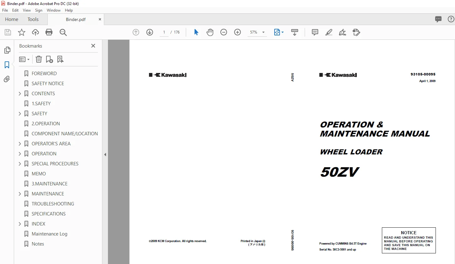
Kawasaki WHEEL LOADER 50ZV OPERATION & MAINTENANCE MANUAL 93105-00095 PDF
$28.95
Kawasaki WHEEL LOADER 50ZV OPERATION & MAINTENANCE MANUAL 93105-00095 – PDF DOWNLOAD
Powered by CUMMINS B4.5T Engine
Serial No. 50C3-5001 and up
Description
Kawasaki WHEEL LOADER 50ZV OPERATION & MAINTENANCE MANUAL 93105-00095 – PDF DOWNLOAD
FILE DETAILS:
Kawasaki WHEEL LOADER 50ZV OPERATION & MAINTENANCE MANUAL 93105-00095 – PDF DOWNLOAD
Language :English
Pages :176
Downloadable : Yes
File Type : PDF
IMAGES PREVIEW OF THE MANUAL:
DESCRIPTION:
Kawasaki WHEEL LOADER 50ZV OPERATION & MAINTENANCE MANUAL 93105-00095 – PDF DOWNLOAD
Powered by CUMMINS B4.5T Engine
Serial No. 50C3-5001 and up
FOREWORD
- Kawasaki pursues a policy of continuing improvement in design and performance of this machine. The right is therefore reserved to vary specifications without prior notice or obliga- tion. This machine gives you, our customer, the maximum in performance and durability, state of the art technology and safety.
- Should you have any question regarding this machine or manual, please contact the Kawasaki dealer in your area during regular business hours. A satisfied customer is our goal. For additional details, for safe and efficient operation and maintenance of your Cummins engine, please refer to your Cummins operation & maintenance manual.
- There may be an optional supplemental operation & maintenance manual, and this also should be referred to when operating machines that are equipped with special packages. This manual is compiled for persons who understand English. If an operator or mainte- nance person does not understand English, please translate what said in this manual into his mother language.
TABLE OF CONTENTS:
Kawasaki WHEEL LOADER 50ZV OPERATION & MAINTENANCE MANUAL 93105-00095 – PDF DOWNLOAD
Powered by CUMMINS B4.5T Engine
Serial No. 50C3-5001 and up
FOREWORD 4
SAFETY NOTICE 5
CONTENTS 6
1SAFETY 11 6
SAFETY 12 6
Safe Operation 12 6
Safe Maintenance 111 6
Safety Signs 116 6
Safety Devices 120 6
2OPERATION 21 6
COMPONENT NAME/LOCATION 22 6
OPERATOR’S AREA 23 6
Pedals and Levers 23 6
Switches 29 6
Indicators 216 6
Seat 222 6
Electrical Protection 224 6
Radio – AM / FM Cassette (24Volt Type) (option) 226 6
Heater or Air Conditioner (option) 234 6
Ride Control System (option) 238 6
OPERATION 239 6
Check before Operation 239 6
Starting the Engine 249 6
Check after Starting the Engine 251 6
Operating the Machine 256 6
Parking 259 6
Stopping the Engine 260 6
Operating Techniques 261 6
SPECIAL PROCEDURES 268 6
Adjustments 268 6
Roading / Special Applications 270 6
Booster Batteries / Jumper Cables 271 6
Towing 273 6
Transportation 274 6
Long Term Storage 276 6
Welding 278 6
3MAINTENANCE 31 7
MAINTENANCE 32 7
Serial Number Location 32 7
Inspection and Maintenance Table 35 7
When Required Inspection and Maintenance 38 7
Every 10 Hours or Daily 317 7
Every 50 Hours or 1 Week 318 7
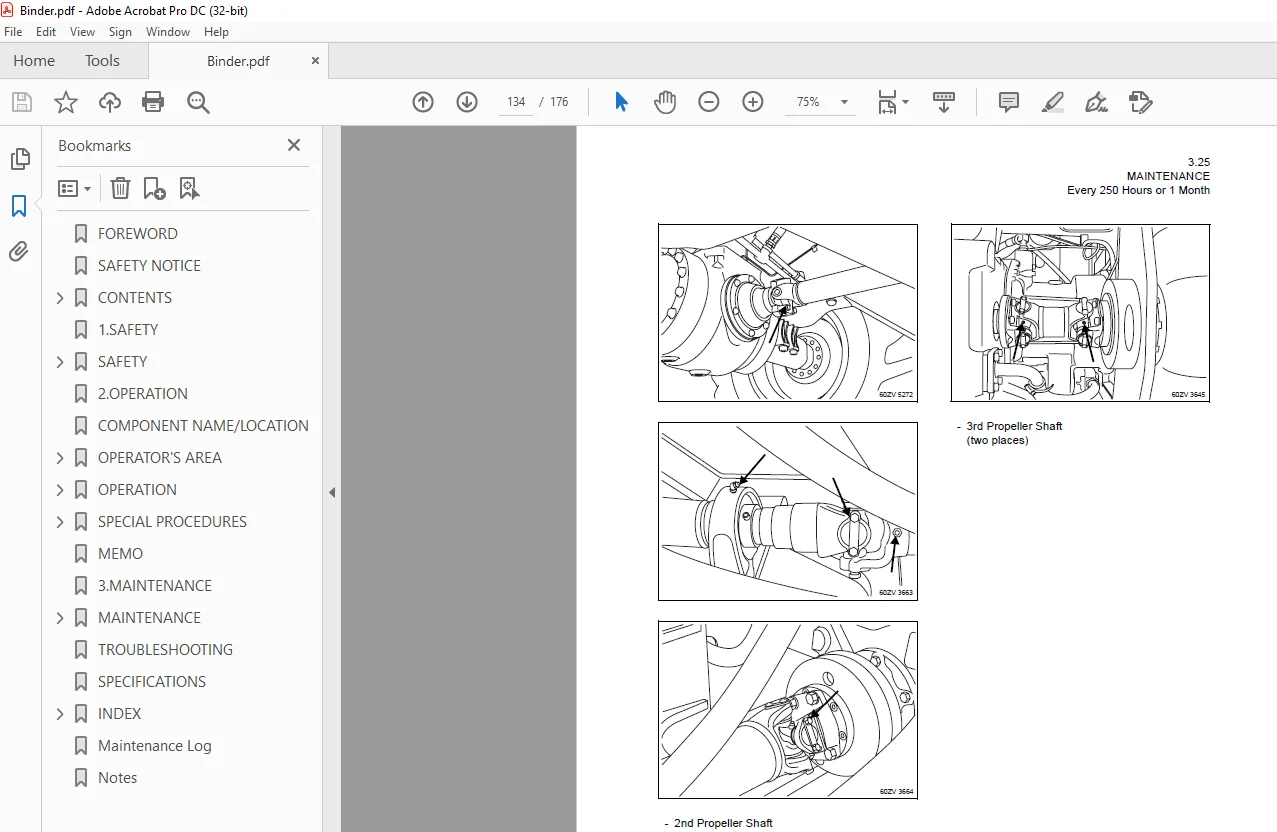
Every 250 Hours or 1 Month 324 7
Every 500 Hours or 3 Months 332 7
Every 1000 Hours or 6 Months 336 7
Every 2000 Hours or 1 Year 342 7
Recommended Lubricants 347 7
Coolant Specification 349 7
TROUBLESHOOTING 350 7
SPECIFICATIONS 355 7
1SAFETY 8
SAFETY 9
Safe Operation 9
Operator Safety 9
Mounting and Dismounting Safety 10
Before Starting Safety 11
Operational Safety 13
Parking Safety 17
Safe Maintenance 18
Safety Preparations Before Maintenance 18
Explosion / Fire / Burn Prevention 20
Other Maintenance Safety Concerns 21
Safety Signs 23
Safety Devices 27
Loading Control Lever Lock 27
Articulation Stopper 27
Neutral Start System 28
Parking Brake Lever 28
ROPS (Roll Over Protective Structure) 29
2OPERATION 30
COMPONENT NAME/LOCATION 31
OPERATOR’S AREA 32
Pedals and Levers 32
1 Transmission Shift Lever 32
2 Horn Button 32
3 High-Low Beam Lever / Turn Signal Lever (option) 33
4 Loading Control Lever 33
5 Auxiliary Attachment Control Lever (option) 34
6 Wrist Rest (adjustable) 35
7 Accelerator Pedal 35
8 Right Brake Pedal 36
9 Left Brake Pedal (Declutch Pedal) 36
10 Steering Column Telescopic Tilt Handle 37
11 Loading Control Lever Lock 37
Switches 38
1 Starter Switch 39
2 Light Switch 39
3 High-Low Beam Lever / Turn Signal Lever (option) 40
4 Front Working Light Switch (Included in cab spec) (option) 40
5 Rear Working Light Switch / Cab Rear Working Light Switch (option) 41
6 Transmission Cut-Off (Declutch) Switch 41
7 Four-way Flasher Switch (option) 42
8 Ride Control Switch (option) 42
9 QUAD (Quick Up And Downshift) Switch 43
10 Front Wiper Switch (Included in cab spec) 43
11 Rear Wiper Switch (Included in cab spec) (option) 44
12 12 Volt Power-outlet Socket (S/N 5009~) 44
Indicators 45
1 Speedometer 46
2 Engine Coolant Temperature Gauge 46
3 Fuel Level Gauge 46
4 Parking Brake Indicator Lamp (red) 46
5 Transmission Cut-Off (Declutch) Lamp (green) 46
6 Working Light Indicator Lamp (green) 47
7 Preheat Indicator Lamp (orange) 47
8 Central Warning Lamp (red) 47
9 Transmission Control Warning Lamp (red) 47
10 Brake Oil Warning Lamp (red) 47
11 Engine Oil Pressure Warning Lamp (red) 48
12 Engine Coolant Temperature Warning Lamp (red) 48
13 Torque Converter Oil Temperature Warning Lamp (red) 48
14 Air Cleaner Warning Lamp (red) 48
15 Charge Lamp (red) 49
16 Turn Signal Indicator Lamp (Left) (green) 49
17 Turn Signal Indicator Lamp (Right) (green) 49
18 High Beam Indicator Lamp (blue) 49
19 Auto Shift Indicator Lamp 49
20 Neutral Indicator Lamp 49
21 Hour Meter 49
22 Secondary Steering Warning Lamp (red) (option) 50
23 Ride Control Indicator Lamp (green) (option) 50
Seat 51
Seat Adjustment 51
Seat Belt 52
Electrical Protection 53
Fuse Boxes 53
Fusible Link 54
Radio – AM / FM Cassette (24Volt Type) (option) 55
Heater or Air Conditioner (option) 63
Ventilation Location and Mode 63
Switches 63
Operation of the Automatic Temperature Control unit 64
Ventilation Location and Mode 65
Switches 65
Ride Control System (option) 67
Operation and Function 67
OPERATION 68
Check before Operation 68
Walk-Around Inspection 68
Greasing 69
Check Engine Oil Level 69
Check Hydraulic Oil Level 70
Check Engine Coolant Level 71
Check Brake Oil Level 71
Drain Water and Sediment from Fuel Filter 72
Check Wiring Harnesses 72
Articulation Stopper 73
Check Tire for Damage, Air and Tread Depth 73
Check Drive Belt 75
Check Air Intake System 75
Check Cooling Fan 76
Check Horn Operation 76
ROPS (Roll Over Protective Structure) (option) 76
Adjust and Check Rear View Mirrors 76
Check Parking Brake 76
Check Monitor Panel Operation 77
Check Control Lever 77
Check Transmission Shift Lever 77
Check Seat Belt Restraint 77
Starting the Engine 78
Normal Start 78
Cold Start 79
Check after Starting the Engine 80
Check Warning Lamps 80
Check Fuel Level 81
Check Transmission Oil Level 81
Check Service Brake Operation 82
Check Parking Brake Operation 83
Check Steering Wheel Operation 83
Check Back-up Alarm Operation 83
Check Exhaust Gas 84
General Inspection 84
Operating the Machine 85
Starting the Machine 85
Starting the Machine on a Grade 86
Speed and Direction Change 86
Parking 88
Stopping the Engine 89
Operating Techniques 90
Loading 90
Excavating 92
Dozing 92
Ground Levelling 93
Carrying 94
Dumping into Truck or Hopper 94
Typical Truck Loading Methods 96
SPECIAL PROCEDURES 97
Adjustments 97
Bucket / Attachment Positioner Adjustment 97
Boom Kickout Adjustment 98
Roading / Special Applications 99
Booster Batteries / Jumper Cables100
Towing102
Transportation103
Long Term Storage105
Before Storage105
During Storage105
After Storage106
Welding107
Cautions Regarding Welding Repair Service107
MEMO109
3MAINTENANCE110
MAINTENANCE111
Serial Number Location111
Inspection and Maintenance Table114
When Required Inspection and Maintenance117
Replace Bucket Teeth (option)117
Replace Cutting Edge (option)118
Replace Seat Belt and Tether119
Clean or Replace Air Cleaner Element119
Clean Radiator Fins121
Check or Replace Fuses121
Check Windshield Washer Fluid122
Clean Air Conditioner Condenser (option)122
Replace Coolant123
Replace Air Conditioner Filter Elements (option)124
Replace Air Conditioner Receiver Dryer (option)125
Check Bucket Stopper125
Every 10 Hours or Daily126
Every 50 Hours or 1 Week127
Greasing127
Check Tire Air Pressure130
Drain Water and Sediment from Fuel Tank131
Check Battery Electrolyte Level132
Every 250 Hours or 1 Month133
Greasing133
Replace Engine Oil and Oil Filter Cartridge135
Check Differential Gear Oil136
Check Tightness of Wheel Bolts137
Check and Adjust Air Conditioner Belt (option)137
Clean Air Conditioner and Heater Filter Element (option)138
Replace Filter140
Every 500 Hours or 3 Months141
Replace Transmission Oil Filter Cartridge141
Replace Fuel Filter Cartridge142
Clean Fuel Prefilter143
Every 1000 Hours or 6 Months145
Replace Transmission Oil145
Clean or Replace Transmission Breather147
Replace Hydraulic Oil Return Filter147
Adjust Parking Brake Lining148
Check Air Conditioner Refrigerant (option)149
Inspect Automatic Belt Tensioner Pulley150
Every 2000 Hours or 1 Year151
Replace Hydraulic Oil, Clean Filter151
Replace Differential Gear Oil153
Clean Fuel Tank154
Replace Filter in the Hydraulic Tank Cap154
Overhaul Brake Master Cylinder155
Check Service Brake Disk Wear155
Check and Adjust Valve Lash Clearance155
Check Ride Control Accumulator (option)155
Recommended Lubricants156
Coolant Specification158
Recommended Mixture of Antifreeze158
TROUBLESHOOTING159
SPECIFICATIONS164
INDEX166
A166
B166
C166
D166
E166
F166
G166
H167
I167
L167
M167
N167
O167
P167
Q167
R167
S167
T167
W168
Maintenance Log169
Notes173
S.M 4/2/2025