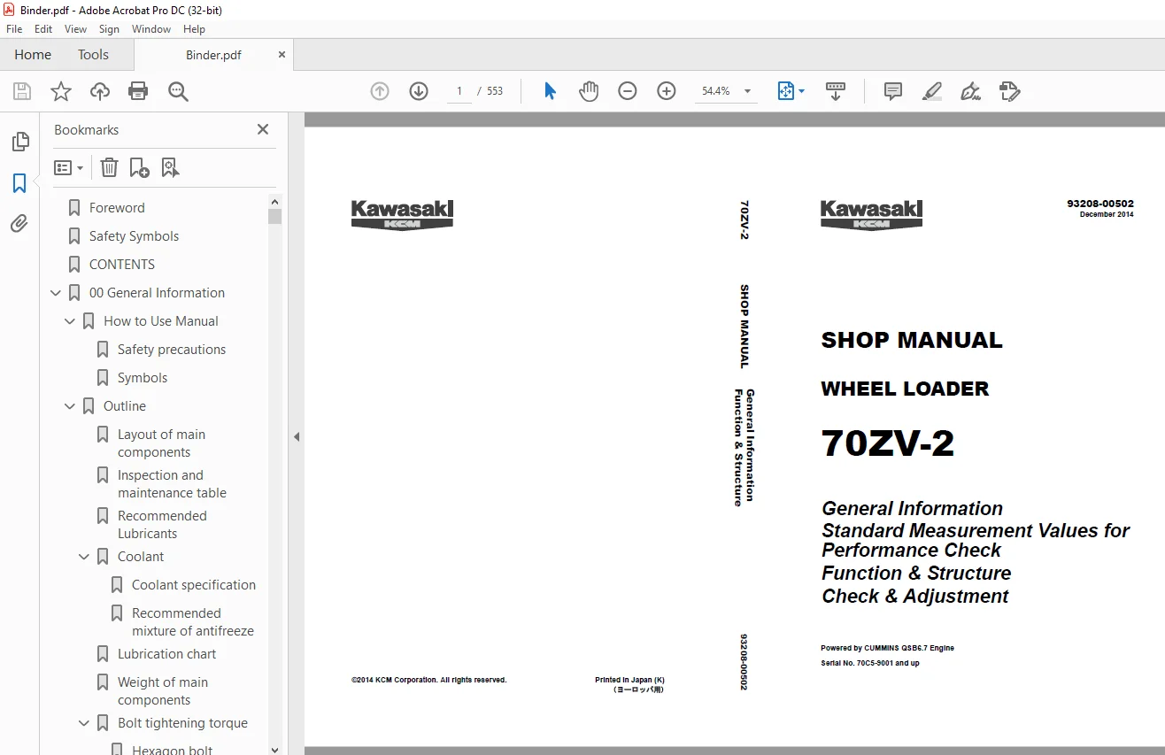
Kawasaki KCM 70ZV-2 WHEEL LOADER SHOP MANUAL 93208-00502 PDF
$30.95
Kawasaki KCM 70ZV-2 WHEEL LOADER SHOP MANUAL 93208-00502 -PDF DOWNLOAD
General Information
Standard Measurement Values for
Performance Check
Function & Structure
Check & Adjustment
Powered by CUMMINS QSB6.7 Engine
Serial No. 70C5-9001 and up
Description
Kawasaki KCM 70ZV-2 WHEEL LOADER SHOP MANUAL 93208-00502 -PDF DOWNLOAD
FILE DETAILS:
Kawasaki KCM 70ZV-2 WHEEL LOADER SHOP MANUAL 93208-00502 -PDF DOWNLOAD
Language :English
Pages :553
Downloadable : Yes
File Type : PDF
IMAGES PREVIEW OF THE MANUAL:
DESCRIPRION:
Kawasaki KCM 70ZV-2 WHEEL LOADER SHOP MANUAL 93208-00502 -PDF DOWNLOAD
General Information
Standard Measurement Values for
Performance Check
Function & Structure
Check & Adjustment
Powered by CUMMINS QSB6.7 Engine
Serial No. 70C5-9001 and up
Foreword
- To ensure good machine performance, reduce failures or problems, and prolong the service life of each component,
it is necessary to operate the machine as is directed in the Operator and Maintenance Manual. - To effectively diagnose and repair the machine, it is important to follow the guidelines laid out in this Shop Manual.
General Information
Function and structure
- For the engine, refer to the engine Shop Manual provided by the engine manufacturer.
- The purpose of this manual is to provide information on the product and the correct maintenance and repair methods.
Please read this manual to ensure correct troubleshooting and good repair service. - This manual will be periodically reviewed and revised for more satisfactory content. If you have any opinion or
requests, please inform us.
TABLE OF CONTENTS:
Kawasaki KCM 70ZV-2 WHEEL LOADER SHOP MANUAL 93208-00502 -PDF DOWNLOAD
General Information
Standard Measurement Values for
Performance Check
Function & Structure
Check & Adjustment
Powered by CUMMINS QSB6.7 Engine
Serial No. 70C5-9001 and up
CONTENTS
00 General Information 00-1
How to Use Manual 00-2
Safety precautions 00-2
Symbols 00-3
Outline 00-4
Layout of main components 00-4
Inspection and maintenance table 00-5
Recommended Lubricants 00-8
Coolant 00-10
Lubrication chart 00-11
Weight of main components 00-12
Bolt tightening torque 00-13
Hose band tightening torque 00-17
Liquid gasket and screw lock agent 00-18
Cautions regarding welding repair service 00-20
03 Measurement for Performance Check 03-1
Cautions on Safety 03-2
Standard Measurement Values for Performance Check 03-3
12 Function & Structure Chassis Group 12-1
Front Chassis 12-2
Loading linkage 12-2
Loading linkage pin 12-4
Rear Chassis 12-5
Fuel tank (S/N 9001~9112) 12-5
Fuel tank (S/N 9113~) 12-6
Floor board mount 12-7
Center Pin 12-8
Upper center pin 12-8
Lower center pin 12-9
Dust seal 12-9
13 Check & Adjustment Chassis Group 13-1
Linkage Pin 13-2
Liner 13-2
Center Pin 13-4
Adjusting shim 13-4
Installing bearing cover 13-5
Installing bearing outer ring 13-6
22 Function & Structure Power Group 22-1
Power Line 22-2
Engine / Transmission 22-3
Engine / transmission mount 22-3
Radiator 22-4
Radiator mount 22-5
Propeller Shaft 22-6
Second propeller shaft assembly 22-7
Third propeller shaft assembly 22-8
Axle Assembly 22-9
Axle Support 22-10
Differential Gear 22-12
Function of TPD 22-14
Operation of TPD 22-15
Limited Slip Differential (option) 22-16
LSD structure 22-16
LSD function 22-19
LSD operation 22-19
23 Check & Adjustment Power Group 23-1
Engine 23-2
Measuring engine speed 23-2
Measuring engine oil pressure 23-3
Propeller Shaft 23-4
Propeller shaft phase 23-4
Second propeller shaft alignment 23-4
Tightening torque 23-5
Axle 23-6
Axle nut tightening procedure 23-6
Differential gear adjustment procedure 23-
32 Function & Structure Torque Converter and Transmission Group 32-1
Torque Converter 32-2
Torque converter structure 32-2
Power flow path 32-2
Torque multiplication 32-2
Torque Converter Gear Pump 32-3
Gear pump specifications 32-3
Transmission 32-4
Clutch combination 32-4
Shift lever position 32-4
Downshift button operation 32-4
Gear train and number of teeth 32-5
Clutch specifications 32-6
Clutch Pack 32-7
Forward and 3rd speed clutches 32-7
Reverse and 2nd speed clutches 32-8
1st speed clutch 32-9
4th speed clutch 32-10
Power Flow Path in the Transmission 32-11
Hydraulic System Diagram 32-14
Hydraulic Circuit Diagram 32-15
Oil Flow 32-16
Oil flow in the torque converter line 32-16
Oil flow to the clutch 32-16
T/C and T/M Oil Circulation 32-17
Control Valve 32-19
System diagram 32-20
Modulation Mechanism 32-21
Clutch control oil pressure curve 32-22
Traveling at forward 1st speed 32-23
Changing from forward 1st speed to reverse 1st speed 32-24
Trimmer engagement 32-25
Clutch engagement starting 32-26
Clutch Solenoid Valve 32-27
For forward/reverse and speed clutches 32-27
For trimmer 32-29
33 Check & Adjustment Torque Converter and Transmission Group 33-1
Clutch Oil Pressure 33-2
Measuring clutch oil pressure 33-2
42 Function & Structure Hydraulic Group 42-1
Flushing Hydraulic Circuit 42-2
Purpose of flushing 42-2
Cautions on Hydraulic Parts Replacement 42-3
Hydraulic Circuit Symbols 42-4
Hydraulic lines 42-4
Pumps & motors 42-4
Cylinders 42-4
Operation methods 42-5
Pressure control valve 42-5
Flow control valve 42-5
Directional control valve 42-6
Check valve 42-6
Miscellaneous hydraulic symbols 42-7
Hydraulic System Operation 42-8
Hydraulic system operation outline 42-8
Layout of Hydraulic Units 42-10
Hydraulic Tank 42-11
Hydraulic tank specifications 42-11
Hydraulic oil level check 42-11
Hydraulic Tank (S/N 9001~9250) 42-12
Hydraulic Tank (S/N 9251~) 42-14
Hydraulic Pump 42-16
Hydraulic pump specifications 42-16
Hydraulic pump principle 42-17
Hydraulic pump wear plate 42-18
Hydraulic pump bushing lubrication 42-18
Hydraulic Cylinder 42-19
Boom cylinder 42-19
Bucket cylinder 42-20
Steering cylinder 42-22
Hydraulic cylinder specifications 42-24
Loading System 42-25
Reducing Valve (for Pilot Pressure) 42-26
Pilot Valve (S/N 9001~9204) 42-27
Pilot Valve (S/N 9205~) 42-33
Multiple Control Valve (KML28/2T102) 42-38
Multiple control valve specifications 42-39
Multiple control valve main relief valve 42-40
Multiple control valve overload relief valve (with make-up function) 42-42
Multiple control valve make-up valve 42-44
Multiple control valve bucket spool 42-45
Multiple control valve boom spool 42-47
Adapter (Orifice) 42-50
Ride Control (OPT) 42-51
Ride control hydraulic circuit 42-51
Ride control function 42-51
Ride control operation 42-52
Ride control valve assembly 42-54
Accumulator (for ride control) 42-59
Steering System 42-60
Priority Valve (S/N 9001~9200) 42-62
Priority valve operation 42-63
Priority Valve (S/N 9201~) 42-66
Priority valve operation 42-67
Orbitrol® 42-70
Valve System 42-70
Orbitrol® structure 42-71
Orbitrol® specification 42-72
Orbitrol® operation 42-73
Orbitrol® feed-back mechanism operation 42-75
Steering speed and flow rate control 42-76
Hydraulic pump oil amount and steering force 42-76
Oil flow change when Q/Amp is operated 42-77
Orbit rotor operation principle 42-78
Auxiliary valves 42-79
Emergency check valve 42-81
Inlet check valve 42-81
Accumulator 42-82
Efficient Loading System (OPT) 42-85
Efficient loading system outline 42-85
Mounting of the ELS valve 42-86
Mounting of the variable kickout sensor 42-88
Efficient loading system operation 42-89
Fan Motor System 42-91
Mounting of fan motor 42-91
Fan Motor Line 42-92
Hydraulic circuit (fan motor normal rotation) 42-94
Reversing Fan Motor Line (OPT) 42-100
Reversing fan motor function 42-100
Hydraulic circuit (Reverse rotation) 42-104
Secondary Steering 42-105
Secondary steering operation 42-106
Secondary steering motor and pump 42-107
43 Check & Adjustment Hydraulic Group 43-1
Loading/Steering Circuit Relief Valve/Ride Control Circuit Reducing Valve (OPT) 43-2
Loading circuit relief valve setting pressures 43-2
Ride control circuit reducing valve setting pressures (OPT) 43-7
Steering circuit relief valve setting pressures 43-
Orbitrol® 42-70
Valve System 42-70
Orbitrol® structure 42-71
Orbitrol® specification 42-72
Orbitrol® operation 42-73
Orbitrol® feed-back mechanism operation 42-75
Steering speed and flow rate control 42-76
Hydraulic pump oil amount and steering force 42-76
Oil flow change when Q/Amp is operated 42-77
Orbit rotor operation principle 42-78
Auxiliary valves 42-79
Emergency check valve 42-81
Inlet check valve 42-81
Accumulator 42-82
Efficient Loading System (OPT) 42-85
Efficient loading system outline 42-85
Mounting of the ELS valve 42-86
Mounting of the variable kickout sensor 42-88
Efficient loading system operation 42-89
Fan Motor System 42-91
Mounting of fan motor 42-91
Fan Motor Line 42-92
Hydraulic circuit (fan motor normal rotation) 42-94
Reversing Fan Motor Line (OPT) 42-100
Reversing fan motor function 42-100
Hydraulic circuit (Reverse rotation) 42-104
Secondary Steering 42-105
Secondary steering operation 42-106
Secondary steering motor and pump 42-107
43 Check & Adjustment Hydraulic Group 43-1
Loading/Steering Circuit Relief Valve/Ride Control Circuit Reducing Valve (OPT) 43-2
Loading circuit relief valve setting pressures 43-2
Ride control circuit reducing valve setting pressures (OPT) 43-7
Steering circuit relief valve setting pressures
Hydraulic Cylinder 43-13
Cylinder natural drift 43-13
52 Function & Structure Brake Group 52-1
Brake System Outline 52-2
Service brake 52-2
Parking brake 52-2
Adjustment of axle internal pressure 52-2
Brake Units Layout 52-3
Unloader Valve 52-4
Unloader valve operation 52-6
Valve Unit 52-7
Accumulator 52-9
In-Line Filter 52-10
Brake Valve 52-11
Brake valve performance chart 52-12
Brake valve outline 52-13
Service Brake 52-16
Service brake operation 52-16
Service brake friction plate 52-17
Service brake steel plate 52-17
Brake circuit air bleeding procedure 52-18
Parking Brake 52-19
Parking brake operation 52-20
Parking brake solenoid valve 52-21
Parking Brake Manual Release 52-22
Parking Brake Spring Chamber 52-24
Brake Circuit Check Valve 52-25
Pressure Sensor (for stop lamp and declutch) 52-26
Pressure sensor (for stop lamp) 52-26
Pressure sensor (for declutch) 52-26
Pressure sensor (for stop lamp) 52-26
53 Check & Adjustment Brake Group 53-1
Brake Circuit Oil Pressure 53-2
Unloader valve setting pressure 53-2
Brake valve oil pressure 53-4
ECM (Engine Controller) 62-23
Function of ECM 62-23
Connection diagram 62-23
Monitor lamp test 62-24
Failure diagnosis 62-25
Quantum fault code information 62-28
Accelerator pedal 62-34
Transmission Control Circuit and Monitor Circuit 62-37
Machine control unit (MCU) 62-37
Machine control unit (MCU) connection diagram (S/N 9001~9300) 62-39
Machine control unit (MCU) connection diagram (S/N 9301~) 62-41
Machine control unit (MCU) function 62-43
Adjustable declutch preset switch 62-48
Monitoring system 62-54
Instrument Panel and Switch 62-56
Instrument panel 62-56
Instrument panel rear surface 62-58
Gauge circuit 62-60
Fuel level sensor 62-62
MODM 62-64
MODM function 62-64
Monitor Changeover 62-64
Information Monitor 62-67
Replacement Monitor 62-71
Fault Log Monitor 62-77
Input/Output Monitor 62-84
Parameter Setting Monitor 62-88
Specification Setting Monitor 62-97
Electrical Detent Circuit 62-103
Bucket leveler 62-103
Detent solenoid 62-104
Lift kickout & lower kickout 62-105
Sensor assy 62-107
Detent solenoid 62-109
Preset height adjustment 62-109
Diode 62-110
Diode check method 62-111
Caution for diode check method 62-111
Surge voltage and surge suppression diodes 62-113
72 Function & Structure Operator Station Group 72-1
Cabin 72-2
Glass 72-3
Wiper mount 72-6
Wiper motor 72-7
Operator Seat 72-9
Steering and Transmission Shift Lever 72-10
Tilt case 72-11
Column shaft 72-12
Shift lever 72-12
Air Conditioner 72-13
Denso air conditioner components 72-13
Denso air conditioner structure 72-14
Function of cooling mechanism 72-19
Cooling circuit 72-22
Electrical circuit 72-23
Air conditioner functions of components 72-24
Charge of refrigerant 72-52
Air conditioner troubleshooting 72-69
73 Check & Adjustment Operator Station Group 73-1
Air Conditioner 73-2
Adjustment of lubricating oil quantity when components of air conditioner are replaced 73-2
Adjustment of air gap (between hub and rotor) in compressor magnetic clutch 73-5
Compressor V-belt adjustment 73-6
Parts to be replaced periodically 73-8
92 Drawing & Diagrams 92-1
Axle Assembly 92-2
Torque Converter and Transmission 92-3
Hydraulic & Brake Circuit 92-4
Brake Circuit 92-5
Electrical Wiring Diagram (1/3) (S/N 9001~9033) 92-6
Electrical Wiring Diagram (2/3) (S/N 9001~9033) 92-7
Electrical Wiring Diagram (3/3) (S/N 9001~9033) 92-8
Electrical Wiring Diagram (1/3) (S/N 9034~9100) 92-9
Electrical Wiring Diagram (2/3) (S/N 9034~9100) 92-10
Electrical Wiring Diagram (3/3) (S/N 9034~9100) 92-11
Electrical Wiring Diagram (1/3) (S/N 9101~9200) 92-12
Electrical Wiring Diagram (2/3) (S/N 9101~9200) 92-13
Electrical Wiring Diagram (3/3) (S/N 9101~9200) 92-14
Electrical Wiring Diagram (1/3) (S/N 9201~9300) 92-15
Electrical Wiring Diagram (2/3) (S/N 9201~9300) 92-16
Electrical Wiring Diagram (3/3) (S/N 9201~9300) 92-17
Electrical Wiring Diagram (1/3) (S/N 9301~) 92-18
Electrical Wiring Diagram (2/3) (S/N 9301~) 92-19
Electrical Wiring Diagram (3/3) (S/N 9301~) 92-20
Electrical Wiring Diagram 92-21
Way of looking at connectors 92-21
Electrical wiring diagram abbreviation chart 92-23
Electrical Wiring Diagram (CAB) 92-25
Electrical Connection Diagram (1/2) (S/N 9001~9100) 92-28
Electrical Connection Diagram (2/2) (S/N 9001~9100) 92-29
Electrical Connection Diagram (1/2) (S/N 9101~9200) 92-30
Electrical Connection Diagram (2/2) (S/N 9101~9200) 92-31
Electrical Connection Diagram (1/2) (S/N 9201~9300) 92-32
Electrical Connection Diagram (2/2) (S/N 9201~9300) 92-33
Electrical Connection Diagram (1/2) (S/N 9301~) 92-34
Electrical Connection Diagram (2/2) (S/N 9301~) 92-35
Electrical Circuit Diagram (Cabin Air Conditioner) 92-36
Electrical Wiring Diagram (Cabin Air Conditioner) 92-37
Equipment Operation Table (Cabin Air Conditioner) 92-38
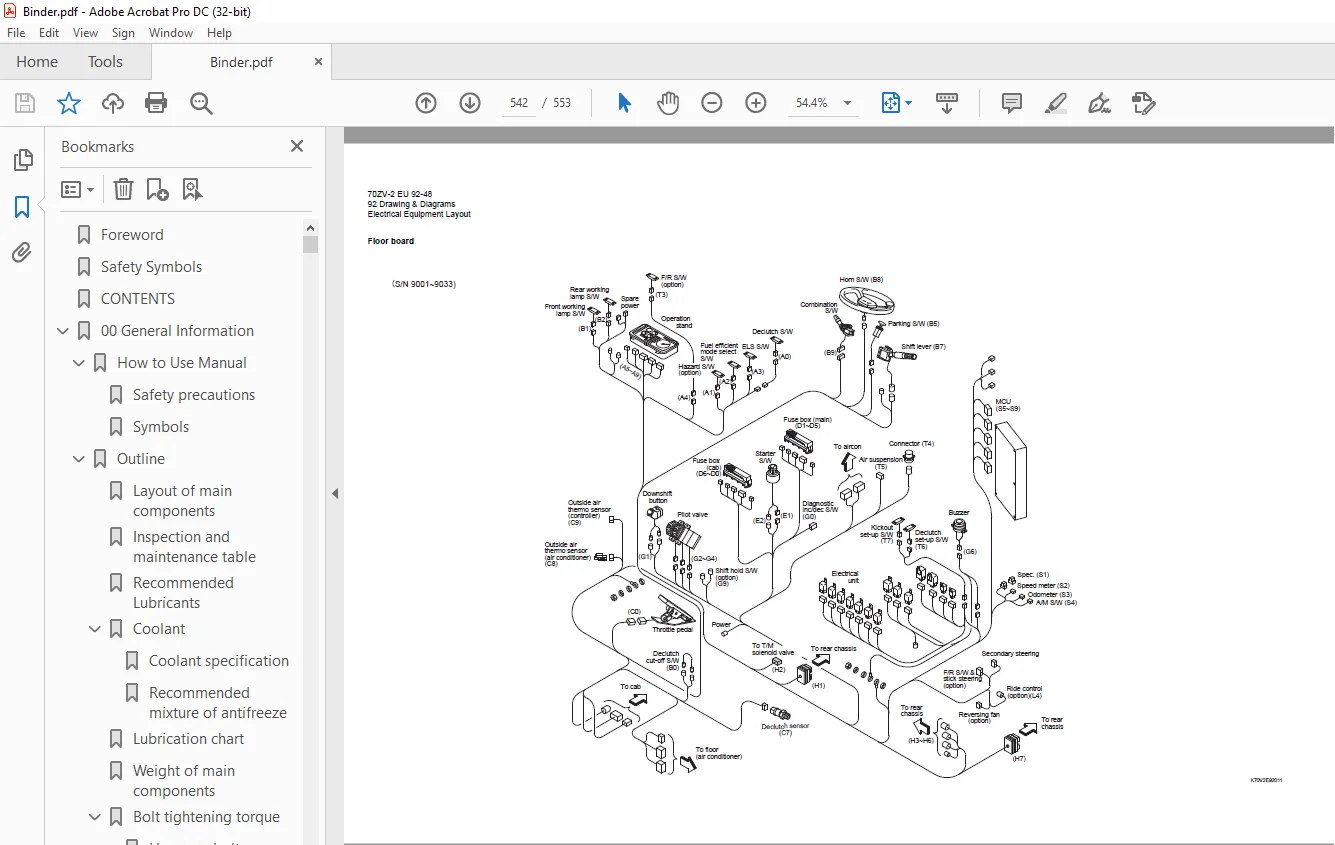
Electrical Equipment Layout 92-39
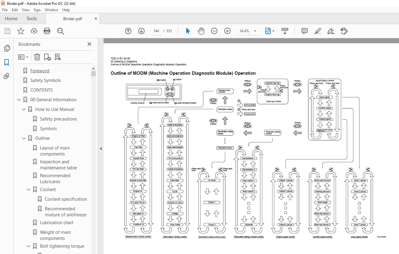
Outline of MODM (Machine Operation Diagnostic Module) Operation 92-50
MODM: Input/Output Monitor – Input/Output Signal Correspondence Table 92-59
S.M 2/2/25