Trusted Business
Verified & Licensed
Virus Free Files
100% Safe Downloads
Secure Payment
SSL Protected
Instant Delivery
Available Immediately
Kawasaki E13C-VV HINO DIESEL ENGINE For Wheel Loaders 90Z7 and 92Z7 Shop Manual PDF
$30.95
Kawasaki E13C-VV HINO DIESEL ENGINE(General Information Engine Diagnosis) For Wheel Loaders 90Z7 and 92Z7 Shop Manual – PDF DOWNLOAD
SN 90H1-5001 and up
92H1-5001 and up
PN 93213-00650
Instant PDF Download
Available immediately
Save to Your Device
Download & keep forever
Antivirus Scanned
100% virus-free
Trusted Worldwide
175,000+ customers
Description
Kawasaki E13C-VV HINO DIESEL ENGINE(General Information Engine Diagnosis) For Wheel Loaders 90Z7 and 92Z7 Shop Manual – PDF DOWNLOAD
FILE DETAILS:
Kawasaki E13C-VV HINO DIESEL ENGINE(General Information Engine Diagnosis) For Wheel Loaders 90Z7 and 92Z7 Shop Manual – PDF DOWNLOAD
SN 90H1-5001 and up
92H1-5001 and up
PN 93213-00650
Language : English
Pages : 563
Downloadable : Yes
File Type : PDF
Pages : 563
Downloadable : Yes
File Type : PDF
IMAGES PREVIEW OF THE MANUAL:
TABLE OF CONTENTS:
Kawasaki E13C-VV HINO DIESEL ENGINE(General Information Engine Diagnosis) For Wheel Loaders 90Z7 and 92Z7 Shop Manual – PDF DOWNLOAD
SN 90H1-5001 and up
92H1-5001 and up
PN 93213-00650
CONTENTS
1 GENERAL
Warning 1-2
How to read this manual 1-3
Precautions for work 1-8
Tightening of engine bolts and nuts 1-12
Tightening of flare nuts and hoses 1-14
Taper thread sealant for piping 1-15
Assembly of joints and gaskets for piping 1-16
Handling of liquid gasket 1-18
Failure diagnosis table for each problem 1-19
Failure diagnosis procedures 1-20
Failure diagnosis using HinoDX 1-22
Connection method of HinoDX 1-27
Engine number 1-28
2 STANDARD VALUE
Engine Mounting/Dismounting 2-2
Fuel System 2-3
Emission Control 2-4
Electrical 2-5
Intake 2-6
Engine Mechanical 2-7
Exhaust 2-13
Cooling 2-14
Lubrication 2-15
Starting and Charging 2-16
Turbocharger 2-20
3 PARTS TO BE PREPARED
Engine Mounting/Dismounting 3-2
Fuel System 3-3
Engine Mechanical 3-4
Exhaust 3-7
Lubrication 3-8
Starting and Charging 3-9
Turbocharger3-11
4 ENGINE MOUNTING/DISMOUNTING
Inspection Before Service 4-2
Engine Mounting/Dismounting 4-4
5 FUEL SYSTEM
Fuel system diagram 5-2
Part layout 5-3
Fuel filter drain 5-10
Replacement of the fuel filter element 5-11
Removal and installation of the fuel filter case 5-13
Replacement of the supply pump 5-15
Injector replacement 5-20
Inspection of the injector 5-27
Replacement of the common rail 5-28
Inspection of the common rail function parts 5-30
6 EMISSION CONTROL
Part layout 6-2
Overhaul of EGR cooler and EGR valve 6-3
7 ELECTRICAL
Part layout 7-2
Layout of the components 7-7
Inspection of the components 7-9
Installation of the components 7-11
Replacement of the stater 7-13
Replacement of the alternator 7-14
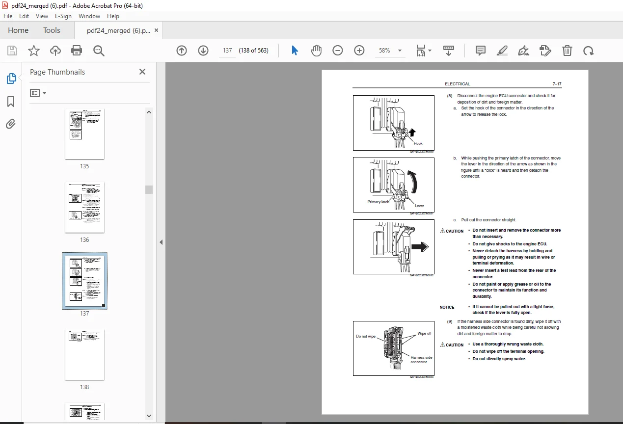
Replacement of the Engine ECU 7-16
Replacement of back pressure sensor 7-22
8 INTAKE
Part layout 8-2
Intake manifold replacement 8-3
9 ENGINE MECHANICAL
Cylinder Head 9-2
Cylinder Block 9-16
Timing Gear Cover and Flywheel Housing 9-21
Main Moving Parts 9-39
Camshaft and Idle Gear 9-62
Valve System 9-85
10 EXHAUST
Exhaust Manifold 10-2
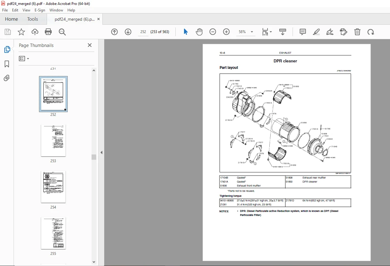
DPR cleaner 10-6
11 COOLING
Cooling system drawing11-2
Part layout11-3
Thermostat case replacement 11-5
Coolant pump replacement11-7
Case sub assembly, coolant pump replacement 11-9
Inspection of thermostat11-10
12 LUBRICATION
Lubrication System 12-2
Oil Cooler 12-8
Oil Pump 12-11
Oil Filter 12-14
Oil Pan 12-16
13 STARTING AND CHARGING
Starter 13-2
Alternator (60A) 13-21
14 TURBOCHARGER
Part layout 14-2
Inspection using HinoDX 14-5
Turbine shaft inspection 14-6
Removal 14-12
Installation 14-16
Inspections after installation 14-22
16 FAILURE DIAGNOSIS FOR EACH ENGINE STATUS
Engine mechanical 16-2
Alternator 16-6
Starter 16-7
Turbocharger 16-8
DPR filter 16-10
17 ENGINE DIAGNOSIS CODE
Engine ECU 17-3
Precautions 17-3
System block diagram 17-4
Inspection 17-5
Table of failure code 17-9
Signal check harness 17-13
Computer pin arrangement 17-15
Check the ECU power supply voltage 17-23
Check the ground 17-24
1 GENERAL
Warning 1-2
How to read this manual 1-3
Precautions for work 1-8
Tightening of engine bolts and nuts 1-12
Tightening of flare nuts and hoses 1-14
Taper thread sealant for piping 1-15
Assembly of joints and gaskets for piping 1-16
Handling of liquid gasket 1-18
Failure diagnosis table for each problem 1-19
Failure diagnosis procedures 1-20
Failure diagnosis using HinoDX 1-22
Connection method of HinoDX 1-27
Engine number 1-28
2 STANDARD VALUE
Engine Mounting/Dismounting 2-2
Fuel System 2-3
Emission Control 2-4
Electrical 2-5
Intake 2-6
Engine Mechanical 2-7
Exhaust 2-13
Cooling 2-14
Lubrication 2-15
Starting and Charging 2-16
Turbocharger 2-20
3 PARTS TO BE PREPARED
Engine Mounting/Dismounting 3-2
Fuel System 3-3
Engine Mechanical 3-4
Exhaust 3-7
Lubrication 3-8
Starting and Charging 3-9
Turbocharger3-11
4 ENGINE MOUNTING/DISMOUNTING
Inspection Before Service 4-2
Engine Mounting/Dismounting 4-4
5 FUEL SYSTEM
Fuel system diagram 5-2
Part layout 5-3
Fuel filter drain 5-10
Replacement of the fuel filter element 5-11
Removal and installation of the fuel filter case 5-13
Replacement of the supply pump 5-15
Injector replacement 5-20
Inspection of the injector 5-27
Replacement of the common rail 5-28
Inspection of the common rail function parts 5-30
6 EMISSION CONTROL
Part layout 6-2
Overhaul of EGR cooler and EGR valve 6-3
7 ELECTRICAL
Part layout 7-2
Layout of the components 7-7
Inspection of the components 7-9
Installation of the components 7-11
Replacement of the stater 7-13
Replacement of the alternator 7-14
Replacement of the Engine ECU 7-16
Replacement of back pressure sensor 7-22
8 INTAKE
Part layout 8-2
Intake manifold replacement 8-3
9 ENGINE MECHANICAL
Cylinder Head 9-2
Cylinder Block 9-16
Timing Gear Cover and Flywheel Housing 9-21
Main Moving Parts 9-39
Camshaft and Idle Gear 9-62
Valve System 9-85
10 EXHAUST
Exhaust Manifold 10-2
DPR cleaner 10-6
11 COOLING
Cooling system drawing11-2
Part layout11-3
Thermostat case replacement 11-5
Coolant pump replacement11-7
Case sub assembly, coolant pump replacement 11-9
Inspection of thermostat11-10
12 LUBRICATION
Lubrication System 12-2
Oil Cooler 12-8
Oil Pump 12-11
Oil Filter 12-14
Oil Pan 12-16
13 STARTING AND CHARGING
Starter 13-2
Alternator (60A) 13-21
14 TURBOCHARGER
Part layout 14-2
Inspection using HinoDX 14-5
Turbine shaft inspection 14-6
Removal 14-12
Installation 14-16
Inspections after installation 14-22
16 FAILURE DIAGNOSIS FOR EACH ENGINE STATUS
Engine mechanical 16-2
Alternator 16-6
Starter 16-7
Turbocharger 16-8
DPR filter 16-10
17 ENGINE DIAGNOSIS CODE
Engine ECU 17-3
Precautions 17-3
System block diagram 17-4
Inspection 17-5
Table of failure code 17-9
Signal check harness 17-13
Computer pin arrangement 17-15
Check the ECU power supply voltage 17-23
Check the ground 17-24
DESCRIPTION:
Kawasaki E13C-VV HINO DIESEL ENGINE(General Information Engine Diagnosis) For Wheel Loaders 90Z7 and 92Z7 Shop Manual – PDF DOWNLOAD
SN 90H1-5001 and up
92H1-5001 and up
PN 93213-00650
Foreword :
- This manual contains special notes, important points, service data and precautions for the removal, installation, disassembly and assembly of major components of the HINO DIESEL ENGINE E13C-VV; Interim Tier 4 compatible engine installed on the Kawasaki 90Z7 Wheel Loader.
- Also, this contains troubleshooting information in accordance with the engine failure status and the generated diagnosis codes.
- To ensure good machine performance, reduce failures or problems, and prolong the service life of each component, it is necessary to operate the machine as is directed in the Operator and Maintenance Manual.
- The purpose of this manual is to provide necessary information when handling the product components and inspection for the correct maintenance and repair methods. To effectively diagnose and repair the machine, it is important to follow the guidelines laid out in this Shop Manual.
- This manual was reproduced with permission from HINO MOTORS LTD
How to read this manual:
1. Scope of repair work:
(1) Repair work is classified into three large categories of “Diagnosis”, “Mounting/removal, replacement, assemblydisassembly and inspectionadjustment” and “Final inspection”.
(2) This manual describes “Diagnosis” in the first process and “Mounting/removal, replacement, assemblydisassembly and inspectionadjustment” in the second process. Explanation of “Final inspection” in the third process is omitted here.
(3) Although the following work is not described in this manual, it should be performed in actual work.
a. Jacking and lifting
b. Cleaning and washing of removed parts as required
c. Visual inspection
2. Standard value:
(1) Standard value, limit, action and tightening torque described in the text are summarized in tables.
3. Items to be prepared
(1) Items to be prepared before work are Special Service Tool (SST), tools, gauges and lubricant, etc. These are listed in the list section of items to be prepared. Items such as general tools, jack, rigid rack, etc. that are usually equipped in general service shop are omitted.
4. How to read sections and titles :
(1) Sections are classified according to J2008, SAE standard.
(2) For areas that show system names like “Engine control system”, “Inspection”, “Adjustment”, “Replacement”, “Overhaul”, etc. of components are described.
(3) For areas that show part names like “Injection pump”, “Mounting/removal and disassembly” is described.
(4) Illustrations of the parts catalog are shown for part layout. (Part codes in the parts catalog are described in the illustration. Major names and tightening torque are listed in the table.)
G.B 05/02/25