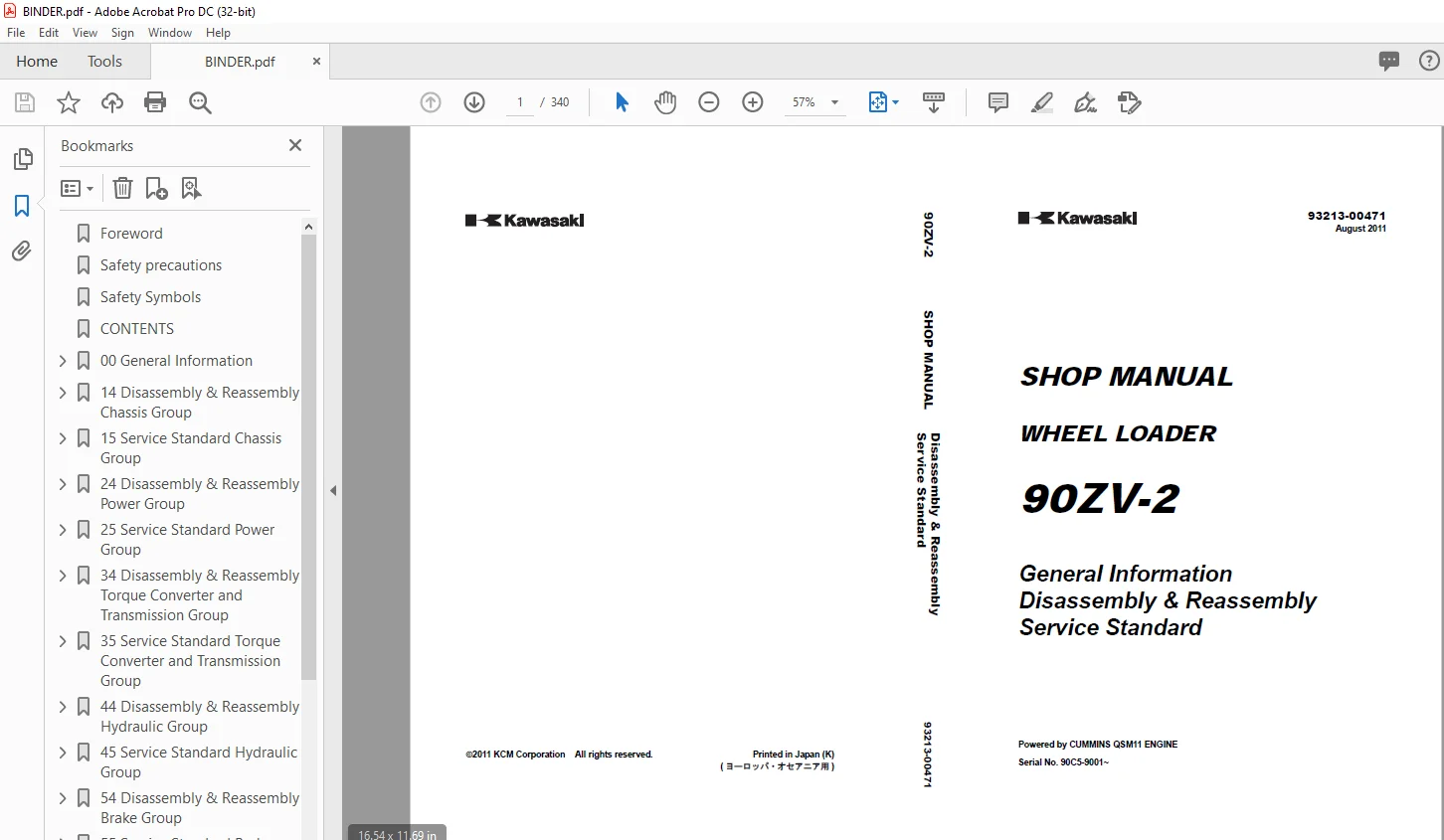
Kawasaki 90ZV-2 WHEEL LOADER SHOP MANUAL 93213-00471 – PDF DOWNLOAD
$28.95
Kawasaki 90ZV-2 WHEEL LOADER SHOP MANUAL 93213-00471 – PDF DOWNLOAD
General Information
Disassembly & Reassembly
Service Standard
Powered by CUMMINS QSM11 ENGINE
Serial No. 90C5-9001~
Description
Kawasaki 90ZV-2 WHEEL LOADER SHOP MANUAL 93213-00471 – PDF DOWNLOAD
FILE DETAILS:
Kawasaki 90ZV-2 WHEEL LOADER SHOP MANUAL 93213-00471 – PDF DOWNLOAD
Language :English
Pages :340
Downloadable : Yes
File Type : PDF
IMAGES PREVIEW OF THE MANUAL:
DESCRIPTION:
Kawasaki 90ZV-2 WHEEL LOADER SHOP MANUAL 93213-00471 – PDF DOWNLOAD
Foreword
- To ensure good machine performance, reduce failures or problems, and prolong the service life of
each component, it is necessary to operate the machine as is directed in the Operator and
Maintenance Manual. - To effectively diagnose and repair the machine, it is important to follow the guidelines laid out
in this Shop Manual.
- For the engine, refer to the engine Shop Manual provided by the engine manufacturer.
- The purpose of this manual is to provide information on the product and the correct maintenance and
repair meth- ods. Please read this manual to ensure correct troubleshooting and good repair
service. - This manual will be periodically reviewed and revised for more satisfactory content. If
you have any opinion or requests, please inform us.
Safety precautions
The most important point in providing repair service is safety. To ensure safety, observe the
general cautions described below.
or repair the machine.
prevent movement.
“DO NOT OPER- ATE!” tag to the steering wheel.
IMPORTANT
If a battery terminal is removed from a machine in less than 30 seconds after the
key is put into the “OFF” position, it can corrupt the ECM program, which can disable
the engine. Always wait 1 full minute to be sure to be past this “write to memory
function” prior to removing battery terminals.
may get burned.
snow, ice, and mud.
certified through an EPA approved testing program.
oil, air, or engine coolant pipe.
the blocks.
a stand or ade- quate cribbing under the unit to prevent unexpected dropping.
TABLE OF CONTENTS:
Kawasaki 90ZV-2 WHEEL LOADER SHOP MANUAL 93213-00471 – PDF DOWNLOAD
General Information
Disassembly & Reassembly
Service Standard
Powered by CUMMINS QSM11 ENGINE
Serial No. 90C5-9001~
Foreword 2
Safety precautions 3
Safety Symbols 4
CONTENTS 6
00 General Information 12
Symbols 13
Weight of Main Components 14
Bolt Tightening Torque 15
Hose Band Tightening Torque 19
Liquid Gasket and Screw Lock Agent 20
Cautions regarding parts removal 20
Cautions regarding reassembly 20
Screw lock agent application procedure 21
How to wind a seal tape 21
Cautions Regarding Welding Repair Service 22
Cautions Regarding Handling of Bearing 24
Bearing installation cautions 24
Interference fits for a bearing 24
Bearing operation test after installation 25
Bearing removal cautions 25
Applying and Storing Articulation Stopper 26
Applying articulation stopper 26
Storing articulation stopper 27
14 Disassembly & Reassembly Chassis Group 28
Deck 29
Deck removing and installing 29
Deck removing 29
Deck installing 30
Fuel Tank 31
Fuel tank removing and installing 31
Fuel tank removing 31
Fuel tank installing 31
Fuel tank installation cautions 31
Hydraulic Tank 32
Hydraulic tank removing and installing 32
Hydraulic tank removing 32
Hydraulic tank installing 34
Hydraulic tank installation cautions 34
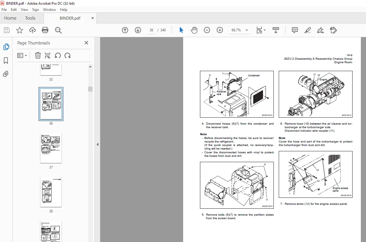
Engine Room 35
Engine room removing and installing 35
Engine room removing 35
Engine room installing 37
Engine room installation cautions 38
Cab 39
Cab removing and installing 39
Cab removing 39
Cab installing 40
Floor Board 41
Floor board removing and installing 41
Floor board removing 41
Floor board installing 43
Floor board installation cautions 43
Boom 44
Boom removing and installing 44
Boom removing 44
Boom installing 46
Boom installation cautions 46
Center Pin 47
Upper center pin 47
Center pin shim adjustment 47
Lower center pin 48
Center pin removing and installing 49
Center pin removing 49
Center pin installing 52
Center pin installation cautions 52
Partition Plate 53
Partition plate removing and installing 53
Partition plate removing 53
Partition plate installing 53
15 Service Standard Chassis Group 54
Linkage 55
Linkage Pin Standard Clearance Values 56
Liner clearance adjustment 56
Center Pin 57
Center pin shim adjustment 57
Bearing cover installing 57
Lower center pin bearing outer ring installing 58
Attachment Leveler 59
Attachment leveler 60
Attachment leveler adjustable angle 60
24 Disassembly & Reassembly Power Group 62
Power Line 63
Power line tightening torque 63
Radiator 64
Radiator tightening torque 64
Radiator removing and installing 66
Radiator removing 66
Radiator installing 69
Radiator installation cautions 69
Fan 70
Fan removing and installing 70
Fan removing 70
Fan installing 71
Fan installation cautions 71
Engine 72
Engine removing and installing 72
Engine removing 72
Engine installing 74
Engine installation cautions 74
Propeller Shaft 75
Propeller shaft removing and installing 75
Second propeller shaft removing 75
Third propeller shaft removing 76
Propeller shaft installing 76
Propeller shaft installation cautions 76
Air Cleaner 77
Air cleaner removing and installing 77
Air cleaner removing 77
Air cleaner installing 78
Air cleaner installation cautions 78
Muffler 79
Muffler removing and installing 79
Muffler removing 79
Muffler installing 80
Muffler installation cautions 80
Front Axle Assembly 81
Front axle assembly tightening torque 81
Axle nut tightening procedure 82
Floating seal installing 82
Front axle assembly removing and installing 83
Front axle assembly removing 83
Front axle assembly installing 84
Front axle assembly installation cautions 85
Air bleeding procedure 86
Front axle disassembling and assembling 87
Front axle disassembling 87
Front axle assembling 90
Front axle assembly cautions 91
Floating seal installing 91
Internal gear hub installing 93
Axle nut tightening 93
Brake adjustment 94
Internal Gear Hub 96
Internal gear hub disassembling and assembling 96
Internal gear hub disassembling 96
Internal gear hub assembling 97
Internal gear hub assembly cautions 98
Spider Assembly 99
Spider assembly disassembling and assembling 99
Spider assembly disassembling 99
Spider assembly assembling 99
Spider assy assembly cautions100
Special Tool101
Special tool for axle101
Rear Axle Assembly105
Rear axle assembly tightening torque105
Axle nut tightening procedure106
Floating seal installing106
Rear axle assembly removing and installing107
Rear axle assembly removing107
Rear axle assembly installing109
Rear axle disassembling and assembling109
Axle Support110
Axle support tightening torque110
Axle support disassembling and assembling111
Axle support disassembling111
Axle support assembling111
Axle support assembly cautions112
Differential Assembly113
Differential assembly removing and installing113
Differential assembly removing113
Differential assembly installing115
Differential assembly installation cautions115
Front differential tightening torque116
Rear differential tightening torque117
Differential assembly disassembling118
Differential assembly assembling122
25 Service Standard Power Group128
Propeller Shaft Service Standard129
Axle and Differential Service Standard130
Axle group130
Differential131
34 Disassembly & Reassembly Torque Converter and Transmission Group132
Torque Converter and Transmission Assembly133
Torque converter and transmission assembly tightening torque133
Torque converter and transmission assembly removing and installing134
Torque converter and transmission assembly removing134
Torque converter and transmission assembly installing139
Transmission assembly installation cautions140
Torque Converter Assembly142
Torque converter assembly bolt tightening torque142
Torque converter assembly disassembling and assembling143
Torque converter assembly disassembling143
Torque converter assembly assembling145
Transmission Assembly150
Transmission assembly bolt tightening torque150
Transmission assembly disassembling and assembling151
Transmission assembly disassembling151
Transmission assembly assembling155
Transmission Forward/Reverse Clutch Pack162
Forward/reverse clutch pack disassembling and assembling162
Forward/reverse clutch pack disassembling162
Forward/reverse clutch pack assembling164
Forward/reverse clutch pack assembly cautions164
Transmission 1st/3rd Speed Clutch Pack165
Transmission 1st/3rd speed clutch pack disassembling and assembling165
Transmission 1st/3rd speed clutch pack disassembling165
Transmission 1st/3rd speed clutch pack assembling166
Transmission 1st/3rd speed clutch pack assembly cautions166
Transmission 2nd Speed Clutch Pack167
Transmission 2nd speed clutch pack disassembling and assembling167
Transmission 2nd speed clutch pack disassembling167
Transmission 2nd speed clutch pack assembling168
Transmission 2nd speed clutch pack assembly cautions168
Transmission 4th Speed Clutch Pack169
Transmission 4th speed clutch pack disassembling and assembling169
Transmission 4th speed clutch pack disassembling169
Transmission 4th speed clutch pack assembling170
Transmission 4th speed clutch pack assembly cautions170
Control Valve Assembly172
Control valve tightening torque172
Control valve removing and installing173
Control valve removing173
Control valve installation cautions174
Control valve disassembling and assembling175
Control valve disassembling175
Control valve assembling176
Control valve assembly cautions176
35 Service Standard Torque Converter and Transmission Group178
Transmission Assembly179
Control Valve180
Gear Pump182
Gear pump specifications182
Clutch Plate Thickness/Piston Stroke183
Clutch plate184
Piston stroke184
Clutch Oil Pressure185
Clutch oil pressure standard value185
44 Disassembly & Reassembly Hydraulic Group186
Hydraulic Parts Removal and Installation Warning187
Hydraulic Parts Disassembly and Assembly Cautions188
Hydraulic parts disassembly cautions188
Hydraulic parts assembly cautions188
Hydraulic Pump Assembly189
Hydraulic pump assembly removing and installing189
Hydraulic pump assembly removing189
Hydraulic pump assembly installing189
Hydraulic pump installation cautions189
Hydraulic pump assembly cross section and tightening torque191
Oil seal replacement procedure192
Hydraulic pump disassembling193
Hydraulic pump assembling197
Hydraulic pump assembly cautions197
Hydraulic Cylinder200
Boom cylinder removing and installing200
Boom cylinder removing200
Boom cylinder installing201
Boom cylinder installation cautions201
Bucket cylinder removing and installing202
Bucket cylinder removing202
Bucket cylinder installing203
Bucket cylinder installation cautions204
Steering cylinder removing and installing205
Steering cylinder removing205
Steering cylinder installing206
Steering cylinder installation cautions206
Hydraulic cylinder disassembling and assembling207
Hydraulic cylinder cross section and tightening torque207
Hydraulic cylinder disassembling209
Hydraulic cylinder assembling211
Hydraulic cylinder assembly cautions212
Pilot Valve (S/N 9001~9353)213
Pilot valve removing and installing213
Pilot valve removing213
Pilot valve installing214
Pilot valve installation cautions214
Pilot valve cross section and tightening torque215
Pilot valve disassembling (S/N 9001~9352)217
Pilot valve assembling225
Pilot valve assembly cautions225
Pilot Valve (S/N 9353~)226
Pilot valve removing and installing226
Pilot valve removing226
Pilot valve installing227
Pilot valve installation cautions227
Pilot valve disassembling (S/N 9353~)229
Pilot valve assembling235
Pilot valve assembly cautions235
Multiple Control Valve236
Multiple control valve removing and installing236
Multiple control valve removing236
Multiple control valve installing237
Multiple control valve installation cautions237
Multiple control valve cross section and tightening torque238
Multiple control valve disassembling239
Multiple control valve assembling241
Multiple control valve assembly cautions241
Orbitrol®242
Orbitrol® removing and installing242
Orbitrol® removing242
Orbitrol® installing243
Orbitrol® installation cautions243
Orbitrol® cross section and tightening torque244
Orbitrol® disassembling245
Orbitrol® assembling248
Steering Valve252
Steering valve removing and installing252
Steering valve removing252
Steering valve installing253
Steering valve installation cautions253
Steering valve cross section and tightening torque254
Steering valve disassembling255
Steering valve assembling256
Stop Valve257
Stop valve removing and installing257
Stop valve removing257
Stop valve installing257
Stop valve installation cautions258
Stop valve disassembling and assembling259
Stop valve cross section and tightening torque259
Stop valve disassembling260
Stop valve assembling260
Fan Motor261
Fan motor removing and installing261
Fan motor removing261
Fan motor installing263
45 Service Standard Hydraulic Group264
Hydraulic Cylinder265
Pilot Valve267
Steering Valve269
54 Disassembly & Reassembly Brake Group270
Unloader Valve271
Unloader valve removing and installing271
Unloader valve removing271
Unloader valve installing272
Unloader valve installation cautions272
Unloader valve cross section and tightening torque273
Unloader valve disassembling276
Unloader valve assembling276
Manifold Valve Assembly277
Valve assembly removing and installing277
Valve assembly removing277
Valve assembly installing278
Valve assembly disassembling and assembling278
Valve assembly cross section and tightening torque279
Accumulator280
Accumulator removing and installing280
Accumulator removing280
Accumulator installing281
Accumulator installation cautions281
Accumulator disassembling and assembling282
Accumulator disassembling282
Accumulator assembling283
Nitrogen gas charging284
Nitrogen gas charging procedure284
Brake Valve286
Brake valve removing and installing286
Brake valve removing286
Brake valve installing287
Brake valve installation cautions287
Brake valve cross section and tightening torque (main valve)288
Brake valve disassembling289
Brake valve assembling292
Brake valve assembly cautions292
Service Brake293
Service brake disassembling and assembling293
Service brake installation cautions293
Parking Brake Actuator294
Parking brake actuator removing and installing294
Parking brake actuator removing294
Parking brake actuator installing294
Parking brake actuator adjusting295
Parking brake actuator adjustment procedure295
Parking brake actuator disassembling and assembling296
Parking brake actuator cross section and tightening torque296
Parking brake actuator disassembling297
Parking brake actuator assembling298
Parking brake actuator assembly cautions298
Parking Brake299
Parking brake removing and installing / disassembling and assembling299
Parking brake removing and disassembling299
Parking brake installing and assembling300
Parking brake (for front) removing and installing301
Parking brake (for front) removing301
Parking brake (for front) installing302
Parking brake installation cautions302
Brake pad assemblies replacement procedure303
Parking brake (for front) disassembling and assembling304
Parking brake (for front) cross section and tightening torque304
Parking brake (for front) disassembling305
Parking brake (for front) assembling305
Parking brake (for front) assembly cautions306
55 Service Standard Brake Group308
Brake Valve309
Service Brake311
Parking Brake312
74 Disassembly & Reassembly Operator Station Group314
Air Conditioner315
Air conditioner removing and installing315
Air conditioner removing315
Air conditioner installing316
Air conditioner disassembling and assembling317
Air conditioner tightening torque317
Air conditioner disassembling320
Air conditioner assembling324
75 Service Standard Operator Station Group326
Air Conditioner327
Periodical Inspection/Servicing327
Tightening Torque327
Tightening torque for hose and pipes327
Tightening torque for screws and bolts in special control regions327
INDEX328
Maintenance Log333
Notes337
S.M 3/2/2025