Trusted Business
Verified & Licensed
Virus Free Files
100% Safe Downloads
Secure Payment
SSL Protected
Instant Delivery
Available Immediately
Kawasaki 85Z7 WHEEL LOADER ISUZU 6HK1 ENGINE Shop Manual – PDF
$32.95
Kawasaki 85Z7 WHEEL LOADER(Disassembly & Reassembly) ISUZU 6HK1 ENGINE Shop Manual – PDF DOWNLOAD
SN 85J1-5001 and up
PN 93211-00600
Instant PDF Download
Available immediately
Save to Your Device
Download & keep forever
Antivirus Scanned
100% virus-free
Trusted Worldwide
175,000+ customers
Description
Kawasaki 85Z7 WHEEL LOADER(Disassembly & Reassembly) ISUZU 6HK1 ENGINE Shop Manual – PDF DOWNLOAD
FILE DETAILS:
Kawasaki 85Z7 WHEEL LOADER(Disassembly & Reassembly) ISUZU 6HK1 ENGINE Shop Manual – PDF DOWNLOAD
SN 85J1-5001 and up
PN 93211-00600
Language : English
Pages : 741
Downloadable : Yes
File Type : PDF
Pages : 741
Downloadable : Yes
File Type : PDF
IMAGES PREVIEW OF THE MANUAL:
TABLE OF CONTENTS:
Kawasaki 85Z7 WHEEL LOADER(Disassembly & Reassembly) ISUZU 6HK1 ENGINE Shop Manual – PDF DOWNLOAD
SN 85J1-5001 and up
PN 93211-00600
SECTION 1 GENERAL INFORMATION
Group 1 Precautions for Disassembling and AssemblingW1-1
Group 2 TighteningW1-2
Group 3 Painting W1-3
Group 4 Bleeding Air W1-4
Group 5 Pressure Release ProcedureW1-5
Group 6 PreparationW1-6
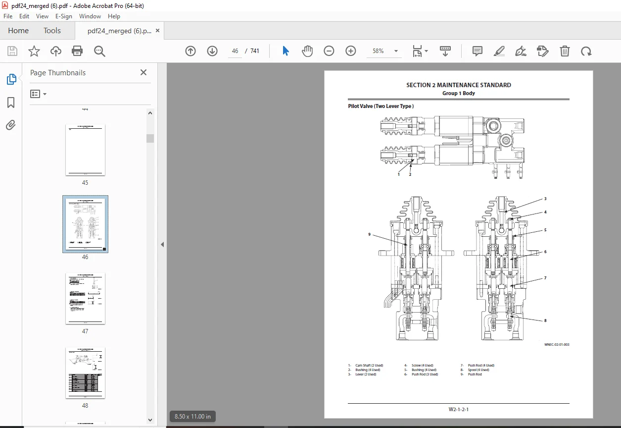
SECTION 2 MAINTENANCE STANDARD
Group 1 Body W2-1
Group 3 Front AttachmentW2-3
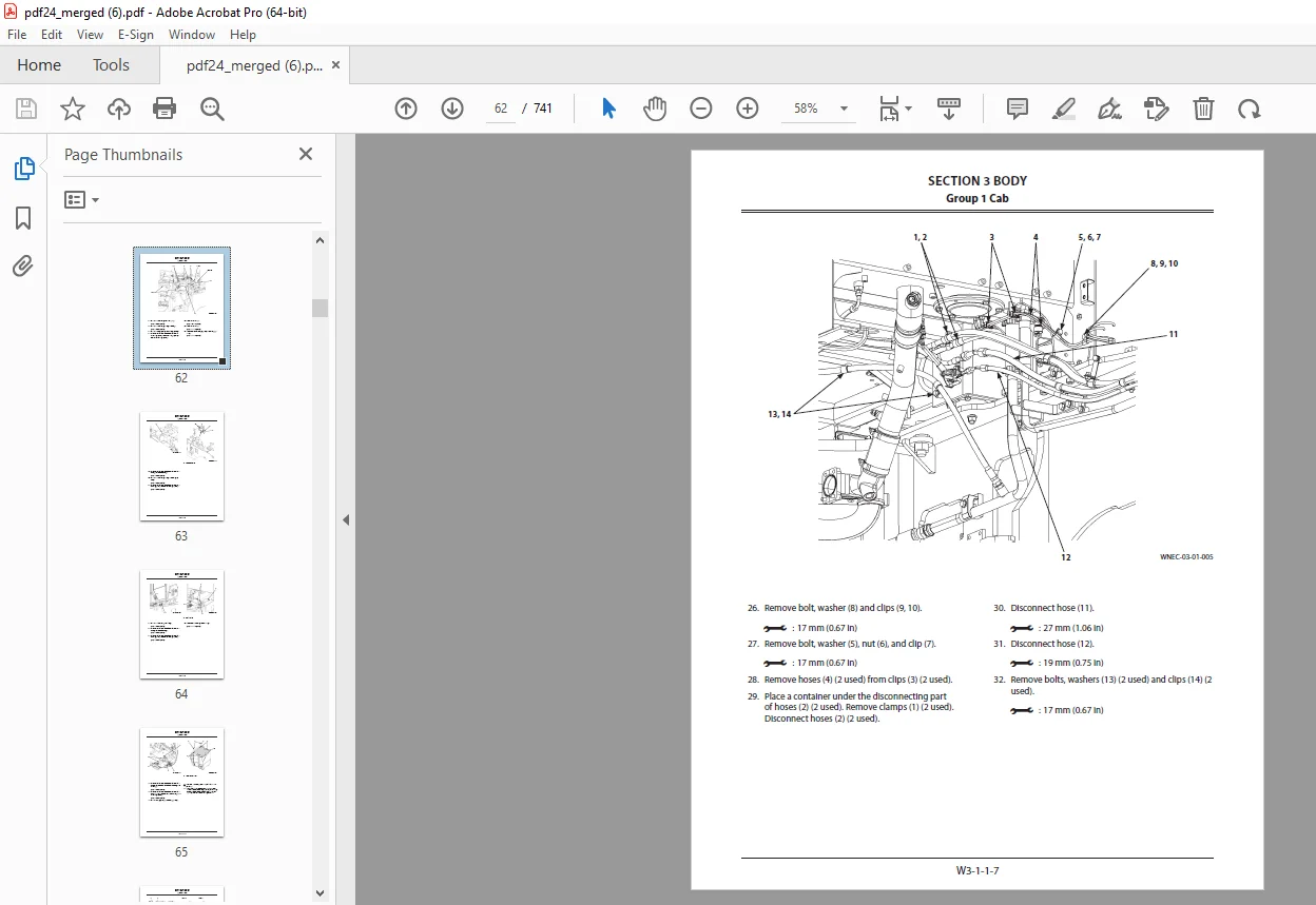
SECTION 3 BODY
Group 1 CabW3-1
Group 2 Counterweight W3-2
Group 3 Center HingeW3-3
Group 4 Engine W3-4
Group 5 Radiator Assembly W3-5
Group 6 Hydraulic Oil Tank W3-6
Group 7 Fuel TankW3-7
Group 8 Pump DeviceW3-8
Group 9 Control ValveW3-9
Group 10 Pilot ValveW3-10
Group 11 Brake Charge Valve W3-11
Group 12 Manifold ValveW3-12
Group 13 Solenoid Valve W3-13
Group 14 Flow Regulator Valve W3-14
Group 15 Cooling Fan SystemW3-15
Group 16 Exhaust Filter W3-16
Group 17 Ride Control Accumulator W3-17
Group 18 Battery Disconnect Switch W3-18
93211-00600
March 2013
85Z7
SECTION 4 TRAVEL SYSTEM
Group 1 Tire W4-1
Group 2 Drive UnitW4-2
Group 3 Axle W4-3
Group 4 Propeller Shaft W4-4
Group 5 Brake Valve W4-5
Group 6 Steering Pilot Valve W4-6
Group 7 Steering Valve W4-7
Group 8 Steering CylinderW4-8
Group 9 Secondary Steering Device W4-9
SECTION 5 FRONT ATTACHMENT
Group 1 Front AttachmentW5-1
Group 2 Cylinder W5-2
Group 1 Precautions for Disassembling and AssemblingW1-1
Group 2 TighteningW1-2
Group 3 Painting W1-3
Group 4 Bleeding Air W1-4
Group 5 Pressure Release ProcedureW1-5
Group 6 PreparationW1-6
SECTION 2 MAINTENANCE STANDARD
Group 1 Body W2-1
Group 3 Front AttachmentW2-3
SECTION 3 BODY
Group 1 CabW3-1
Group 2 Counterweight W3-2
Group 3 Center HingeW3-3
Group 4 Engine W3-4
Group 5 Radiator Assembly W3-5
Group 6 Hydraulic Oil Tank W3-6
Group 7 Fuel TankW3-7
Group 8 Pump DeviceW3-8
Group 9 Control ValveW3-9
Group 10 Pilot ValveW3-10
Group 11 Brake Charge Valve W3-11
Group 12 Manifold ValveW3-12
Group 13 Solenoid Valve W3-13
Group 14 Flow Regulator Valve W3-14
Group 15 Cooling Fan SystemW3-15
Group 16 Exhaust Filter W3-16
Group 17 Ride Control Accumulator W3-17
Group 18 Battery Disconnect Switch W3-18
93211-00600
March 2013
85Z7
SECTION 4 TRAVEL SYSTEM
Group 1 Tire W4-1
Group 2 Drive UnitW4-2
Group 3 Axle W4-3
Group 4 Propeller Shaft W4-4
Group 5 Brake Valve W4-5
Group 6 Steering Pilot Valve W4-6
Group 7 Steering Valve W4-7
Group 8 Steering CylinderW4-8
Group 9 Secondary Steering Device W4-9
SECTION 5 FRONT ATTACHMENT
Group 1 Front AttachmentW5-1
Group 2 Cylinder W5-2
DESCRIPTION:
Kawasaki 85Z7 WHEEL LOADER(Disassembly & Reassembly) ISUZU 6HK1 ENGINE Shop Manual – PDF DOWNLOAD
SN 85J1-5001 and up
PN 93211-00600
Precautions for Disassembling and Assembling:
Precautions for Disassembling:
- Clean the Machine Thoroughly wash the machine before bringing it into the shop. Bringing a dirty machine into the shop may cause machine components to be contaminated during disassembling / assembling, resulting in damage to machine components, as well as decreased efficiency in service work.
- Inspect the Machine Be sure to thoroughly understand all disassembling / assembling procedures beforehand to help avoid incorrect disassembling of components as well as personal injury. Check and record the items listed below to prevent problems from occurring in the future.
- The machine model, machine serial number, and hour meter reading.
- Reason for disassembly (symptoms, failed parts, and causes).
- Clogging of filters and oil, water or air leaks, if any. Capacities and condition of lubricants.
- Loose or damaged parts.
- Prepare and Clean Tools and Disassembly Area Prepare the necessary tools to be used and the area for disassembling work. Precautions for Disassembling and Assembling
- Precautions for Disassembling
- Cap the open ends in case the hoses and pipes have been disconnected. In addition, attach an identification tag onto the connectors, hoses, and pipes for assembling.
- Before disassembling, clean the exterior of the components and place on a workbench.
- Drain hydraulic oil and gear oil from the hydraulic components and reduction gear.
- Be sure to provide appropriate containers for draining fluids.
- Use matching marks for easier reassembling if necessary.
- Be sure to use the specified special tools when instructed.
Maintenance Standard Terminology “Standard”:
1. Dimension for parts on a new machine.
2. Dimension of new components or assemblies adjusted to specification. Allowable errors will be indicated if necessary
G.B 05/02/25