

John Deere Powertech Plus 9.0L Disel Engines Level 14 Electronic Fuel System With Denso HPCR Technical Manual – PDF DOWNLOAD
DESCRIPTION:
John Deere Powertech Plus 9.0L Disel Engines Level 14 Electronic Fuel System With Denso HPCR Technical Manual – PDF DOWNLOAD
For complete service information also see:
PowerTech Plusä 9.0L Diesel Engines—
Base Engine. . . . . . . . . . . . . . . . . . . . . . . . . . CTM400
Alternators and Starter Motors. . . . . . . . . . . CTM77
OEM Engine Accessories . . . . . . CTM67 (English Only)
Forward :
This manual is written for an experienced technician. Essential tools required in performing certain service work are identified in this manual and are recommended for use. This manual (CTM385) covers only Level 14 Electronic Fuel System with the Denso High Pressure Common Rail (HPCR). The following manual covers the base engine.
· CTM400—Base Engine
Other manuals will be added in the future to provide additional information on electronic fuel systems as needed. Live with safety: Read the safety messages in the introduction of this manual and the cautions presented throughout the text of the manual.
TABLE OF CONTENTS:
John Deere Powertech Plus 9.0L Disel Engines Level 14 Electronic Fuel System With Denso HPCR Technical Manual – PDF DOWNLOAD
Contents 3
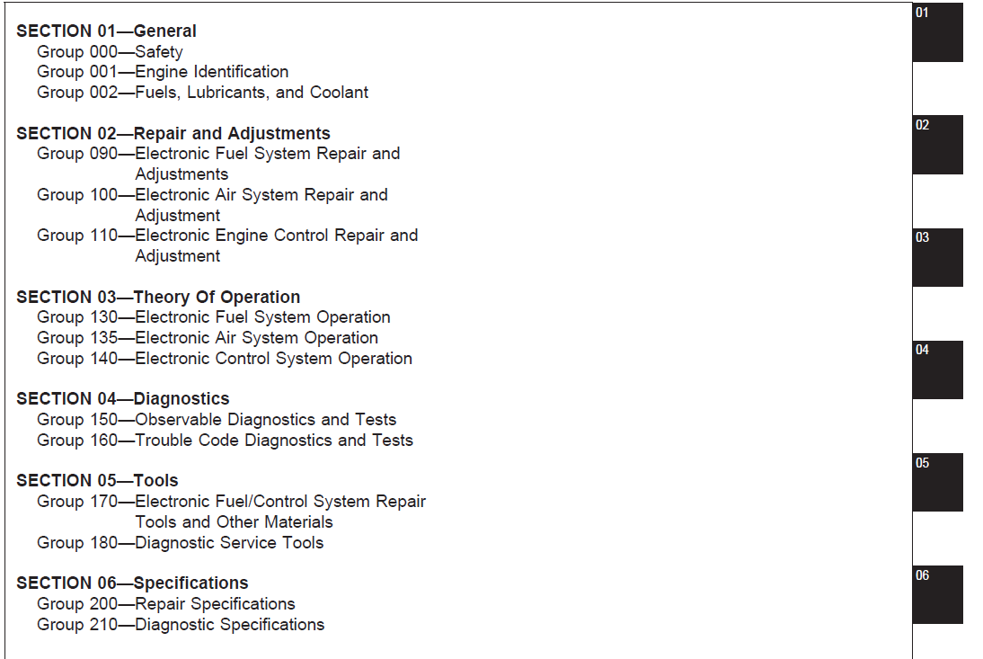
General 5
Safety 7
Handle Fluids Safely—Avoid Fires 7
Handle Starting Fluid Safely 7
Service Cooling System Safely 7
Prevent Battery Explosions 8
Prepare for Emergencies 8
Handling Batteries Safely 9
Avoid High-Pressure Fluids 10
Wear Protective Clothing 10
Service Machines Safely 11
Work In Ventilated Area 11
Work in Clean Area 11
Remove Paint Before Welding or Heating 12
Avoid Heating Near Pressurized Fluid Lines 12
Illuminate Work Area Safely 13
Use Proper Lifting Equipment 13
Construct Dealer-Made Tools Safely 13
Practice Safe Maintenance 14
Use Proper Tools 14
Dispose of Waste Properly 15
Live With Safety 15
Engine Identification 17
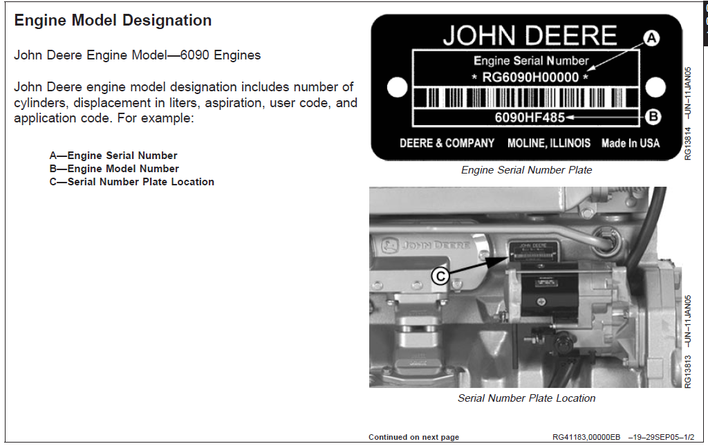
Engine Model Designation 17
Engine Serial Number Plate Information 19
Engine Option Code Label 20
Information Relative to Emissions Regulations 20
Engine Application Charts 21
Fuels, Lubricants, and Coolant 23
Lubricants and Coolant 23
Diesel Fuel 23
Bio-Diesel Fuel 24
Dieselscan Fuel Analysis 24
Lubricity of Diesel Fuel 25
Repair and Adjustments 27
Electronic Fuel System Repair and Adjustments 29
Fuel System – General Information 29
Relieve Fuel System Pressure 29
Remove and Install Fuel Filters 30
Remove and Install Fuel Transfer Pump Assembly 32
Remove and Install High Pressure Fuel Pump Assembly 34
Remove and Install High Pressure Common Rail 39
Remove and Install Flow Dampers 42
Remove and Install Pressure Limiter 45
Remove and Install Leak-off Lines 46
Remove and Install Electronic Injectors (EIs) 50
Clean Electronic Injector (EI) Bore 55
Clean Electronic Injector (EI) Orifice 55
Clean Electronic Injector (EI) Body 55
Inspect Electronic Injector (EI) Body 55
Electronic Air System Repair and Adjustment 57
Remove and Install Exhaust Gas Recirculation (EGR) Valve 57
Electronic Engine Control Repair and Adjustment 59
Engine Control Unit (ECU) Maintenance 59
Fuel System Sensors 60
Remove and Install Fuel Rail Pressure Sensor 61
Connectors 62
Use Electrical Insulating Compound 62
Using High-Pressure Washer 63
Repair Cinch Flex Box Connector 63
Repair WEATHERPACK™ Connector 70
Remove Blade Terminals from Connector Body 73
Repair (Pull Type) METRI-PACK™ Connectors 74
Repair (Push Type) METRI-PACK™ Connectors 76
Repair DEUTSCH™ Connectors 79
Repair SUMITOMO™ Connectors 82
Repair YAZAKI™ Connectors 84
Theory Of Operation 87
Electronic Fuel System Operation 89
About This Group 89
Fuel System Operation 90
Fuel Transfer Pump Operation 91
Primary Filter Operation 92
Secondary Fuel Filter Operation 93
High Pressure Fuel Pump Operation 94
High Pressure Common Rail (HPCR) Operation 95
Electronic Injector (EI) Operation 96
Electronic Air System Operation 99
About This Group 99
VGT-EGR System Operation100
Turbocharger101
Turbo Actuator102
EGR Cooler103
EGR Valve104
Air Intake Manifold105
Electronic Control System Operation107
About This Group107
Electronic Control System Terminology108
Electronic Control System Operation109
Engine Control Unit (ECU) Self-Diagnosis110
Sensor Locations112
Monitoring Engine Parameters114
Measuring Temperature115
Measuring Pressure116
Measuring Speed117
Crankshaft Position Sensor118
Pump Position Sensor119
Exhaust Gas Recirculation (EGR) Exhaust Temperature Sensor120
Fresh Air Temperature Sensor121
Exhaust Gas Recirculation (EGR) Mixed Temperature Sensor122
Engine Control Unit (ECU) Temperature Sensor123
Engine Coolant Temperature (ECT) Sensor123
Barometric Air Pressure (BAP) Sensor124
Fuel Temperature Sensor124
Turbo Compressor Inlet Temperature Sensor125
Turbo Turbine Inlet Temperature126
Exhaust Pressure Sensor127
Fuel Rail Pressure Sensor128
Fuel Transfer Pump Pressure Sensor129
Manifold Air Pressure (MAP) Sensor130
Oil Pressure Sensor131
Turbo Speed Sensor132
Pump Control Valve (PCV)133
Water in Fuel (WIF) Sensor134
Measuring Throttle Position135
Analog Throttle135
Multi-state Throttle138
Dual-state Throttle139
Tri-state Throttle139
Ramp Throttle140
Measuring Speed141
Engine Coolant Level Switch142
Sensor Supply #1143
Sensor Supply #2144
Sensor Supply #3146
Sensor Supply #4148
Sensor Supply #5150
Engine Control Unit (ECU)152
Intake Air Heater Operation154
Controlled Area Network (CAN)155
Cruise Control Operation156
Engine Protection157
Derate Programs157
Multiple Torque Curve Selection158
Governor Droop Mode Selection158
Diagnostics159
Observable Diagnostics and Tests169
About This Group169
E1 – Engine Cranks/Won’t Start170
E1 – Engine Cranks/Won’t Start Diagnostic Procedure170
170
170
171
171
171
172
172
173
173
173
E2 – Engine Misfires/Runs Irregularly174
E2 – Engine Misfires/Runs Irregularly Diagnostic Procedure174
174
174
174
175
175
175
175
175
176
176
176
176
176
177
177
177
177
178
178
E3 – Engine Does Not Develop Full Power179
E3 – Engine Does Not Develop Full Power Diagnostic Procedure179
179
179
180
180
181
181
181
182
182
182
183
183
183
184
E4 – Engine Emits Excessive White Exhaust Smoke185
E4 – Engine Emits Excessive White Exhaust Smoke Diagnostic Procedure185
185
185
185
186
186
186
186
E5 – Engine Emits Excessive Black or Gray Exhaust Smoke187
E5 – Engine Emits Excessive Black or Gray Exhaust Smoke Diagnostic Procedure187
187
187
187
188
188
E6 – Engine Will Not Crank189
E7 – Engine Idles Poorly189
E8 – Abnormal Engine Noise190
E9 – Analog Throttle (A) Does Not Respond191
E10 – Analog Throttle (B) Does Not Respond192
F1 – Fuel Supply System Check194
F1 – Fuel Supply System Check Diagnostic Procedure194
194
194
194
195
195
195
195
196
196
196
196
197
197
197
F2 – Excessive Fuel Consumption198
F3 – Fuel in Oil199
D1 – ECU Does Not Communicate with Service ADVISOR200
D1 – ECU Does Not Communicate with Service ADVISOR Diagnostic Procedure200
200
201
201
202
202
202
202
203
203
203
D2 – Diagnostic Gauge Does Not Communicate With ECU204
D2 – Diagnostic Gauge Does Not Communicate With ECU Diagnostic Procedure204
204
204
205
205
205
206
206
206
207
207
A1 – Intake Air Heater Check208
A1 – Intake Air Heater Check Diagnostic Procedure208
208
209
209
209
210
210
Check Fuel Supply Quality211
Test for Air in Fuel212
Check Fuel Supply Pressure213
Check for Restricted Fuel Leak-off Line213
Check High Pressure Fuel Pump Static Timing214
Check for Fuel in Oil214
Trouble Code Diagnostics and Tests215
About This Group215
Electrical Concepts216
Using a Digital Multimeter216
Electrical Circuit Malfunctions217
Troubleshooting Circuit Malfunctions220
Connecting to Service ADVISOR224
Viewing Active DTCs on Diagnostic Gauge228
Viewing Stored DTCs on Diagnostic Gauge231
Clearing Stored DTCs on Diagnostic Gauge233
Data Parameter Description234
Engine Test Instructions—Cylinder Misfire Test240
Engine Test Instructions—Compression Test241
Engine Test Instructions— Cylinder Cutout Test242
Exhaust Gas Recirculation Valve Reset243
Turbocharger Learn Value Reset244
Reprogramming Engine Control Unit (ECU)246
John Deere Trimmable Options246
Downloading Electronic Injector Calibration Files247
Electronic Injector Calibration251
Diagnostic Trouble Codes (DTCs)257
Failure Mode Indicator Designations258
Listing of Diagnostic Trouble Codes (DTCs) on ECU261
Diagnostic Procedure266
Intermittent Fault Diagnostics267
T1 — Multi-state Throttle Input High268
T1 — Multi-state Throttle Input High Diagnostic Procedure268
268
269
269
269
270
270
T2 — Multi-state Throttle Input Low271
T2 — Multi-state Throttle Input Low Diagnostic Procedure271
271
272
272
272
273
T3 — Analog Throttle (A) Input High274
T3 — Analog Throttle (A) Input High Diagnostic Procedure274
274
275
275
275
276
276
T4 — Analog Throttle (A) Input Low277
T4 — Analog Throttle (A) Input Low Diagnostic Procedure277
277
278
278
278
279
279
279
280
T5 — Analog Throttle (B) Input High281
T5 — Analog Throttle (B) Input High Diagnostic Procedure281
281
282
282
282
283
283
T6 — Analog Throttle (B) Input Low284
T6 — Analog Throttle (B) Input Low Diagnostic Procedure284
284
285
285
285
286
286
286
287
T22 — Analog Throttle (A) Input Voltage Out of Range288
T22 — Analog Throttle (A) Input Voltage Out of Range Diagnostic Procedure288
288
289
289
289
290
T23 — Multi-State Voltage Out of Range291
T23 — Multi-State Voltage Out of Range Diagnostic Procedure291
291
292
292
292
293
T24 — Analog Throttle (B) Input Voltage Out of Range294
T24 — Analog Throttle (B) Input Voltage Out of Range Diagnostic Procedure294
294
295
295
295
296
00002803 — Throttle Voltage High297
00002804 — Throttle Voltage Low298
00002814 — Throttle Voltage Out of Range299
00002903 — Throttle Voltage High300
00002904 — Throttle Voltage Low301
00002914 — Throttle Voltage Out of Range302
00009103 — Throttle Voltage High303
00009104 — Throttle Voltage Low304
00009114 — Throttle Voltage Out of Range305
00009403 — Fuel Transfer Pump Pressure Input Voltage High306
00009403 — Fuel Transfer Pump Pressure Input Voltage High Diagnostic Procedure306
306
307
307
307
308
308
308
308
00009404 — Fuel Transfer Pump Pressure Input Voltage Low309
00009404 — Fuel Transfer Pump Pressure Input Voltage Low Diagnostic Procedure309
309
310
310
310
311
311
311
311
312
00009417 — Fuel Transfer Pump Pressure Low Least Severe313
00009417 — Fuel Transfer Pump Pressure Low Least Severe Procedure313
314
314
314
315
315
315
315
316
316
317
317
00009703 — Water-in-Fuel Signal Voltage High318
00009703 — Water-in-Fuel Signal Voltage High Diagnostic Procedure318
318
319
319
319
320
320
320
320
00009704 — Water-in-Fuel Signal Voltage Low321
00009704 — Water-in-Fuel Signal Voltage Low Diagnostic Procedure321
321
322
322
322
323
323
323
00009716 — Water in Fuel Detected324
00009716 — Water in Fuel Detected Diagnostic Procedure324
325
325
325
326
00010001 — Engine Oil Pressure Extremely Low327
00010001 — Engine Oil Pressure Extremely Low Diagnostic Procedure327
328
328
328
328
00010003 — Engine Oil Pressure Input Voltage High329
00010003 — Engine Oil Pressure Input Voltage High Diagnostic Procedure329
330
330
330
331
331
331
331
332
00010004 — Engine Oil Pressure Input Voltage Low333
00010004 — Engine Oil Pressure Input Voltage Low Diagnostic Procedure333
334
334
334
335
335
335
335
336
336
00010018 — Engine Oil Pressure Moderately Low337
Engine Oil Pressure Moderately Low Diagnostic Procedure337
337
338
338
338
00010031 — Engine Oil Pressure Invalid339
00010031 — Engine Oil Pressure Invalid Diagnostic Procedure339
339
340
00010202 — Manifold Air Pressure Invalid341
00010202 — Manifold Air Pressure Invalid Diagnostic Procedure341
341
342
342
342
343
00010203 — Manifold Air Pressure Input Voltage High344
00010203 — Manifold Air Pressure Input Voltage High Diagnostic Procedure344
344
345
345
345
346
346
346
346
00010204 — Manifold Air Pressure Input Voltage Low347
00010204 — Manifold Air Pressure Input Voltage Low Diagnostic Procedure347
347
348
348
348
349
349
349
349
350
00010300 — Turbo Overspeed Most Severe351
00010300 — Turbo Overspeed Most Severe Diagnostic Procedure351
352
352
352
353
353
353
353
354
00010302 — Turbo Speed Mismatch355
00010302 — Turbo Speed Mismatch Diagnostic Procedure355
355
356
356
356
357
357
357
357
358
00010305 — Turbo Speed Sensor Current Low359
00010305 — Turbo Speed Sensor Current Low Diagnostic Procedure359
359
360
360
360
00010306 — Turbo Speed Sensor Current High361
00010306 — Turbo Speed Sensor Current High Diagnostic Procedure361
361
362
362
362
00010308 — Turbo Speed Invalid363
00010308 — Turbo Speed Invalid Diagnostic Procedure363
363
364
364
364
365
365
365
365
366
00010331 — Turbo Speed Missing367
00010331 — Turbo Speed Missing Diagnostic Procedure367
367
368
368
368
369
00010500 — Exhaust Gas Recirculation (EGR) Mixed Air Temperature Extremely High370
00010500 — Exhaust Gas Recirculation (EGR) Mixed Air Temperature Extremely High Diagnostic Procedure370
370
371
371
371
00010503 — Exhaust Gas Recirculation (EGR) Mixed Air Temperature Input Voltage High372
00010503 — Exhaust Gas Recirculation (EGR) Mixed Air Temperature Input Voltage High Diagnostic Procedure372
373
373
373
374
374
374
375
375
375
376
00010504 — Exhaust Gas Recirculation (EGR) Mixed Air Temperature Input Voltage Low377
00010504 — Exhaust Gas Recirculation (EGR) Mixed Air Temperature Input Voltage Low Diagnostic Procedure377
377
378
378
378
379
379
379
00010515 — Exhaust Gas Recirculation (EGR) Mixed Air Temperature High Least Severe380
00010515 — Exhaust Gas Recirculation (EGR) Mixed Air Temperature High Least Severe Diagnostic Procedure380
380
381
381
381
00010516 — Exhaust Gas Recirculation (EGR) Mixed Air Temperature Moderately High382
00010516 — Exhaust Gas Recirculation (EGR) Mixed Air Temperature Moderately High Diagnostic Procedure382
382
383
383
383
00010700 — Air Filter Restriction High384
00010700 — Air Filter Restriction High Diagnostic Procedure384
384
384
385
00010802 — Barometric Air Pressure Invalid386
00010802 — Barometric Air Pressure Invalid Diagnostic Procedure386
386
00010831 — Barometric Air Pressure Error387
00010831 — Barometric Air Pressure Error Diagnostic Procedure387
387
388
00011000 — Engine Coolant Temperature Extremely High389
00011000 — Engine Coolant Temperature Extremely High Diagnostic Procedure389
00011003 — Engine Coolant Temperature Input Voltage High390
00011003 — Engine Coolant Temperature Input Voltage High Diagnostic Procedure390
391
391
391
392
392
392
392
393
393
393
00011004 — Engine Coolant Temperature Input Voltage Low394
00011004 — Engine Coolant Temperature Input Voltage Low Diagnostic Procedure394
395
395
395
396
396
396
396
00011015 — Engine Coolant Temperature High Least Severe397
00011015 — Engine Coolant Temperature High Least Severe Diagnostic Procedure397
397
397
398
398
398
00011016 — Engine Coolant Temperature Moderately High399
00011016 — Engine Coolant Temperature Moderately High Diagnostic Procedure399
00011017 — Engine Coolant Temperature Low Least Severe400
00011015 — Engine Coolant Temperature Low Least Severe Diagnostic Procedure400
400
401
401
401
00011101 — Engine Coolant Level Low402
00011101 — Engine Coolant Level Low Diagnostic Procedure402
403
403
403
404
404
404
405
00015703 — Fuel Rail Pressure Input Voltage High406
00015703 — Fuel Rail Pressure Input Voltage High Diagnostic Procedure406
407
407
407
408
408
00015704 — Fuel Rail Pressure Input Voltage Low409
00015704 — Fuel Rail Pressure Input Voltage Low Diagnostic Procedure409
410
410
410
411
00015710 — Fuel Rail Pressure Loss Detected412
00015710 — Fuel Rail Pressure Loss Detected Diagnostic Procedure412
412
413
413
414
414
00015717 — Fuel Rail Pressure Not Developed415
00015717 — Fuel Rail Pressure Not Developed Diagnostic Procedure415
415
416
416
416
417
417
417
418
419
00015817 — ECU Power Down Error420
00015817 — ECU Power Down Error Diagnostic Procedure420
420
421
421
00017400 — Fuel Temperature Extremely High422
00017400 — Fuel Temperature Extremely High Diagnostic Procedure422
423
423
423
423
424
424
00017403 — Fuel Temperature Input Voltage High425
00017403 — Fuel Temperature Input Voltage High Diagnostic Procedure425
425
426
426
426
427
427
427
427
428
428
00017404 — Fuel Temperature Input Voltage Low429
00017404 — Fuel Temperature Input Voltage Low Diagnostic Procedure429
429
430
430
430
431
431
431
00017416 — Fuel Temperature Moderately High432
00017416 — Fuel Temperature Moderately High Diagnostic Procedure432
432
433
433
433
433
434
00018900 — Engine Speed Derate435
00018900 — Engine Speed Derate435
435
00019000 — Engine Overspeed Extreme436
00019000 — Engine Overspeed Extreme Diagnostic Procedure436
436
00019016 — Engine Overspeed Moderate437
00019016 — Engine Overspeed Moderate Diagnostic Procedure437
437
00023702 — VIN Security Data Conflict437
00023702 — VIN Security Data Conflict438
438
00023713 — VIN Option Code Invalid439
00023713 — VIN Option Code Invalid439
439
00023731 — Vehicle Model Number Invalid440
00023731 — Vehicle Model Number Invalid440
440
00041200 — Exhaust Gas Recirculation (EGR) Exhaust Temperature Extremely High441
00041200 — Exhaust Gas Recirculation (EGR) Exhaust Temperature Extremely High Diagnostic Procedure441
441
442
442
442
443
443
443
444
00041203 — Exhaust Gas Recirculation (EGR) Exhaust Temperature Input Voltage High445
00041203 — Exhaust Gas Recirculation (EGR) Exhaust Temperature Input Voltage High Diagnostic Procedure445
445
446
446
446
447
447
447
447
448
448
00041204 — Exhaust Gas Recirculation (EGR) Exhaust Temperature Input Voltage Low449
00041204 — Exhaust Gas Recirculation (EGR) Exhaust Temperature Input Voltage Low Diagnostic Procedure449
449
450
450
450
451
451
451
00041216 — Exhaust Gas Recirculation (EGR) Exhaust Temperature Moderately High452
Exhaust Gas Recirculation (EGR) Exhaust Temperature Moderately High Diagnostic Procedure452
452
453
453
453
454
454
454
455
00041218 — EGR Temperature Lower Than Expected456
Exhaust Gas Recirculation (EGR) Exhaust Temperature Low Diagnostic Procedure456
456
457
457
457
458
458
00061103 — Electronic Injector Wiring Shorted To Power Source459
00061103 — Electronic Injector Wiring Shorted To Power Source Diagnostic Procedure459
459
460
460
460
461
461
461
00061104 — Electronic Injector Wiring Shorted To Ground462
00061104 — Electronic Injector Wiring Shorted To Ground Diagnostic Procedure462
462
463
463
463
464
464
465
465
00062003 — Sensor Supply 2 Voltage High466
00062003 — Sensor Supply 2 Voltage High Diagnostic Procedure466
467
467
467
00062004 — Sensor Supply 2 Voltage Low468
00062004 — Sensor Supply 2 Voltage Low Diagnostic Procedure468
469
469
470
470
00062701 — Electronic Injector Supply Voltage Problem471
00062701 — Electronic Injector Supply Voltage Problem Diagnostic Procedure471
471
472
472
472
473
473
474
00062716 — ECU Power Supply Voltage Higher Than Expected475
00062716 — ECU Power Supply Voltage Higher Than Expected475
475
476
476
00062718 — ECU Power Supply Voltage Lower Than Expected477
00062718 ECU Power Supply Voltage Lower Than Expected Diagnostic Procedure477
477
478
478
478
479
00062912 — ECU Failure480
00062912 — ECU Failure Diagnostic Procedure480
480
481
481
481
00062913 — ECU Error482
00062913 — ECU Error Diagnostic Procedure482
482
483
483
483
00063602 — Pump Position Sensor Input Noise484
00063602 — Pump Position Sensor Input Noise Diagnostic Procedure484
484
485
485
00063605 — Pump Position Sensor Current Low486
00063605 — Pump Position Sensor Current Low Diagnostic Procedure486
486
487
487
487
00063606 — Pump Position Sensor Current High488
00063606 — Pump Position Sensor Current High Diagnostic Procedure488
488
489
489
489
00063608 — Pump Position Sensor Input Missing490
00063608 — Pump Position Sensor Input Missing Diagnostic Procedure490
490
491
491
491
492
492
00063610 — Pump Position Sensor Input Pattern Error493
00063610 — Pump Position Sensor Input Pattern Error Diagnostic Procedure493
494
494
494
495
495
496
00063702 — Crank Position Input Noise497
00063702 — Crank Position Input Noise Diagnostic Procedure497
498
498
498
00063705 — Crank Position Sensor Current Low499
00063705 — Crank Position Sensor Current Low Diagnostic Procedure499
499
500
500
500
00063706 — Crank Position Sensor Current High501
00063706 — Crank Position Sensor Current High Diagnostic Procedure501
501
502
502
502
00063707 — Crank Position/Pump Position Timing Moderately Out of Sync503
00063707 — Crank Position/Pump Position Timing Moderately Out of Sync Diagnostic Procedure503
503
504
504
504
505
505
505
506
506
506
507
507
00063708 — Crank Position Input Missing508
00063708 — Crank Position Input Missing Diagnostic Procedure508
509
509
509
510
510
510
511
00063710 — Crank Position Input Pattern Error512
00063710 — Crank Position Input Pattern Error Diagnostic Procedure512
513
513
513
514
514
514
515
515
00064011 — Engine Shutdown—Vehicle Request Invalid515
00064031 — Engine Shutdown—Vehicle Request516
00064031 — Engine Shutdown – Vehicle Request Diagnostic Procedure516
516
00064104 — Turbo Actuator Error517
00064104 — Turbo Actuator Error Diagnostic Procedure517
518
518
518
519
519
519
00064105 — Turbo Actuator Current Low520
00064105 — Turbo Actuator Current Low Diagnostic Procedure520
520
521
521
521
522
00064112 — ECU/Turbo Communication Error523
ECU/Turbo Communication Error Diagnostic Procedure523
523
524
524
524
525
00064113 — Turbo Actuator Learned Value Error526
Turbo Actuator Learned Value Error Diagnostic Procedure526
527
527
527
528
00064116 — Turbo Actuator Temperature Moderately High529
00064116 — Turbo Actuator Temperature Moderately High Diagnostic Procedure529
529
530
530
530
530
531
00064705 — Fan Drive Output 1 Shorted or Open531
00064707 — Fan Drive Output 2 Shorted or Open531
00065102 — Cylinder 1 Electronic Injector Part Number Invalid532
00065102 — Cylinder 1 Electronic Injector Part Number Invalid Diagnostic Procedure532
532
533
533
00065105 — Cylinder 1 Electronic Injector Circuit Open534
00065105 — Cylinder 1 Electronic Injector Circuit Open Diagnostic Procedure534
534
535
535
536
536
537
00065106 — Cylinder 1 Electronic Injector Circuit Shorted538
00065106 — Cylinder 1 Electronic Injector Circuit Shorted Diagnostic Procedure538
538
539
539
540
540
00065107 — Cylinder 1 Electronic Injector Mechanical Failure541
00065107 — Cylinder 1 Electronic Injector Mechanical Failure Diagnostic Procedure541
541
542
542
542
543
543
00065113 — Cylinder 1 Electronic Injector QR Code Invalid544
00065113 — Cylinder 1 Electronic Injector QR Code Invalid Diagnostic Procedure544
544
545
545
00065202 — Cylinder 2 Electronic Injector Part Number Invalid546
00065202 — Cylinder 2 Electronic Injector Part Number Invalid Diagnostic Procedure546
546
547
547
00065205 — Cylinder 2 Electronic Injector Circuit Open548
00065205 — Cylinder 2 Electronic Injector Circuit Open Diagnostic Procedure548
548
549
549
550
550
551
00065206 — Cylinder 2 Electronic Injector Circuit Shorted552
00065206 – Cylinder 2 Electronic Injector Circuit Shorted Diagnostic Procedure552
552
553
553
554
554
00065207 — Cylinder 2 Electronic Injector Mechanical Failure555
00065207 — Cylinder 2 Electronic Injector Mechanical Failure Diagnostic Procedure555
555
556
556
556
557
557
00065213 — Cylinder 2 Electronic Injector QR Code Invalid558
00065213 – Cylinder 2 Electronic Injector QR Code Invalid Diagnostic Procedure558
558
559
559
00065302 — Cylinder 3 Electronic Injector Part Number Invalid560
00065202 — Cylinder 3 Electronic Injector Part Number Invalid Diagnostic Procedure560
560
561
561
00065305 — Cylinder 3 Electronic Injector Circuit Open562
00065305 — Cylinder 3 Electronic Injector Circuit Open Diagnostic Procedure562
562
563
563
564
564
565
00065306 — Cylinder 3 Electronic Injector Circuit Shorted566
00065306 – Cylinder 3 Electronic Injector Circuit Shorted Diagnostic Procedure566
566
567
567
568
568
00065307 — Cylinder 3 Electronic Injector Mechanical Failure569
00065307 — Cylinder 3 Electronic Injector Mechanical Failure Diagnostic Procedure569
569
570
570
570
571
571
00065313 — Cylinder 3 Electronic Injector QR Code Invalid572
00065313 – Cylinder 3 Electronic Injector QR Code Invalid Diagnostic Procedure572
572
573
573
00065402 — Cylinder 4 Electronic Injector Part Number Invalid574
00065202 — Cylinder 4 Electronic Injector Part Number Invalid Diagnostic Procedure574
574
575
575
00065405 — Cylinder 4 Electronic Injector Circuit Open576
00065405 – Cylinder 4 Electronic Injector Circuit Open Diagnostic Procedure576
576
577
577
578
578
579
00065406 — Cylinder 4 Electronic Injector Circuit Shorted580
00065406 – Cylinder 4 Electronic Injector Circuit Shorted Diagnostic Procedure580
580
581
581
582
582
00065407 — Cylinder 4 Electronic Injector Mechanical Failure583
00065407 — Cylinder 4 Electronic Injector Mechanical Failure Diagnostic Procedure583
583
584
584
584
585
585
00065413 — Cylinder 4 Electronic Injector QR Code Invalid586
00065413 – Cylinder 4 Electronic Injector QR Code Invalid Diagnostic Procedure586
586
587
587
00065502 — Cylinder 5 Electronic Injector Part Number Invalid588
00065502 – Cylinder 5 Electronic Injector Part Number Invalid Diagnostic Procedure588
588
589
589
00065505 — Cylinder 5 Electronic Injector Circuit Open590
00065505 — Cylinder 5 Electronic Injector Circuit Open Diagnostic Procedure590
590
591
591
592
592
593
00065506 — Cylinder 5 Electronic Injector Circuit Shorted594
00065506 — Cylinder 5 Electronic Injector Circuit Shorted Diagnostic Procedure594
594
595
595
596
596
00065507 — Cylinder 5 Electronic Injector Mechanical Failure597
00065507 — Cylinder 5 Electronic Injector Mechanical Failure Diagnostic Procedure597
597
598
598
598
599
599
00065513 — Cylinder 5 Electronic Injector QR Code Invalid600
00065513 – Cylinder 5 Electronic Injector QR Code Invalid Diagnostic Procedure600
600
601
601
00065602 — Cylinder 6 Electronic Injector Part Number Invalid602
00065602 – Cylinder 6 Electronic Injector Part Number Invalid Diagnostic Procedure602
602
603
603
00065605 — Cylinder 6 Electronic Injector Circuit Open604
00065605 – Cylinder 6 Electronic Injector Circuit Open Diagnostic Procedure604
604
605
605
606
606
607
00065606 — Cylinder 6 Electronic Injector Circuit Shorted608
00065606 – Cylinder 6 Electronic Injector Circuit Shorted Diagnostic Procedure608
608
609
609
610
610
00065607 — Cylinder 6 Electronic Injector Mechanical Failure611
00065607 — Cylinder 6 Electronic Injector Mechanical Failure Diagnostic Procedure611
611
612
612
612
613
613
00065613 — Cylinder 6 Electronic Injector QR Code Invalid614
00065613 – Cylinder 6 Electronic Injector QR Code Invalid Diagnostic Procedure614
614
615
615
00089809 — Vehicle Speed or Torque Message Invalid616
00089809 – Vehicle Speed or Torque Message Invalid Diagnostic Procedure616
616
617
617
617
618
00097002 Auxiliary Engine Shutdown Switch Signal Invalid Diagnostic Procedure618
618
618
619
619
619
620
00097031 — Engine Shutdown – Auxiliary Request621
00097031 — Engine Shutdown – Auxiliary Request Diagnostic Procedure621
621
00097131 — Engine Derate – Auxiliary Request622
00097131 — Engine Derate – Auxiliary Request Diagnostic Procedure622
623
00107505 — Fuel Transfer Pump Current Low624
00107505 — Fuel Transfer Pump Current Low624
624
625
625
625
625
626
626
00107506 — Fuel Transfer Pump Current High627
00107506 — Fuel Transfer Pump Current High627
627
628
628
628
628
00107512 — Fuel Transfer Pump Error629
00107512 — Fuel Transfer Pump Error629
629
630
00107903 — Sensor Supply 3 Voltage High631
00107903 — Sensor Supply 3 Voltage High Diagnostic Procedure631
632
632
632
00107904 — Sensor Supply 3 Voltage Low633
00107904 — Sensor Supply 3 Voltage Low Diagnostic Procedure633
634
634
634
635
00108003 — Sensor Supply 1 Voltage High636
00108003 — Sensor Supply 1 Voltage High Diagnostic Procedure636
637
637
637
00108004 — Sensor Supply 1 Voltage Low638
00108004 — Sensor Supply 1 Voltage Low Diagnostic Procedure638
639
639
639
640
00110931 — Engine Protection Shutdown Warning641
00111031 — Engine Protection Shutdown642
00113600 — ECU Temperature Extremely High643
00113600 — ECU Temperature Extremely High Diagnostic Procedure643
643
644
644
00113616 — ECU Temperature Moderately High645
00113616 — ECU Temperature Moderately High Diagnostic Procedure645
645
646
646
00117203 — Turbo Compressor Inlet Temperature Input Voltage High647
00117203 — Turbo Compressor Inlet Temperature Input Voltage High Diagnostic Procedure647
647
648
648
648
649
649
649
649
650
650
00117204 — Turbo Compressor Inlet Temperature Input Voltage Low651
00117204 — Turbo Compressor Inlet Temperature Input Voltage Low Diagnostic Procedure651
651
652
652
652
653
653
653
00117216 — Turbo Compressor Inlet Temperature Moderately High654
00117216 — Turbo Compressor Inlet Temperature Moderately High Diagnostic Procedure654
654
655
655
655
655
656
00118000 — Turbo Turbine Inlet Temperature Extremely High657
00118000 — Turbo Turbine Inlet Temperature Extremely High Diagnostic Procedure657
658
658
658
659
659
00118016 — Turbo Turbine Inlet Temperature Moderately High660
00118016 – Turbo Turbine Inlet Temperature Moderately High Diagnostic Procedure660
661
661
661
662
662
00120902 — Exhaust Pressure Invalid663
00120902 – Exhaust Pressure Invalid Diagnostic Procedure663
663
664
664
664
665
00120903 — Exhaust Pressure Input Voltage High666
00120903 — Exhaust Pressure Input Voltage High Diagnostic Procedure666
666
667
667
667
668
668
668
668
00120904 — Exhaust Pressure Input Voltage Low669
00120904 — Exhaust Pressure Input Voltage Low Diagnostic Procedure669
670
670
670
671
671
671
671
672
672
00134703 — Pump Control Valve Current High673
00134703 — Pump Control Valve Current High Diagnostic Procedure673
673
674
674
674
00134705 — Pump Control Valve Current Mismatch675
00134705 — Pump Control Valve Current Mismatch Diagnostic Procedure675
675
676
676
676
677
677
00134707 — Fuel Rail Pressure Control Error678
00134707 — Fuel Rail Pressure Control Error Diagnostic Procedure678
679
679
679
680
00138215 — Primary Fuel Filter Plugged680
00156802 — Torque Curve Selection Invalid680
00156802—Torque Curve Selection Invalid Diagnostic Procedure681
681
00156931 — Fuel Derate681
00163901 — Fan Speed Signal Missing682
00163901 — Fan Speed Signal Missing Diagnostic Procedure682
00163916 — Fan Speed Higher Than Expected683
00163961 — Fan Speed Higher Than Expected Diagnostic Procedure683
00163918 — Fan Speed Lower Than Expected684
00163961 — Fan Speed Lower Than Expected Diagnostic Procedure684
00200013 — Security Violation685
00200509 — ACU Message Missing685
00200509 — ACU Message Missing Diagnostic Procedure686
686
00203009 — CAB Message Missing686
00203009 — CAB Message Missing Diagnostic Procedure687
687
00207109 — CCU Message Missing687
00207109 — CCU Message Missing Diagnostic Procedure688
688
00263000 — Exhaust Gas Recirculation (EGR) Fresh Air Temperature Extremely High689
00263000 – Exhaust Gas Recirculation (EGR) Fresh Air Temperature Extremely High Diagnostic Procedure689
689
690
690
690
691
691
691
00263003 — Exhaust Gas Recirculation (EGR) Fresh Air Temperature Input Voltage High692
00263003 — Exhaust Gas Recirculation (EGR) Fresh Air Temperature Input Voltage High Diagnostic Procedure692
692
693
693
693
694
694
694
695
695
695
00263004 — Exhaust Gas Recirculation (EGR) Fresh Air Temperature Input Voltage Low696
00263004 — Exhaust Gas Recirculation (EGR) Fresh Air Temperature Input Voltage Low Diagnostic Procedure696
696
697
697
697
698
698
698
00263015 — Exhaust Gas Recirculation (EGR) Fresh Air Temperature High Least Severe699
00263015 – Exhaust Gas Recirculation (EGR) Fresh Air Temperature High Least Severe Diagnostic Procedure699
699
700
700
700
701
701
701
00263016 — Exhaust Gas Recirculation (EGR) Fresh Air Temperature Moderately High702
00263016 – Exhaust Gas Recirculation (EGR) Fresh Air Temperature Moderately High Diagnostic Procedure702
702
703
703
703
704
704
704
00265902 — Exhaust Gas Recirculation (EGR) Flow/Temperature Mismatch705
Exhaust Gas Recirculation (EGR) Flow/Temperature Mismatch Diagnostic Procedure705
705
706
706
706
707
707
708
708
709
709
710
710
00265915 — Exhaust Gas Recirculation (EGR) Flow Rate High Least Severe711
Exhaust Gas Recirculation (EGR) Flow Rate High Least Severe Diagnostic Procedure711
711
712
712
712
713
713
713
714
714
00265917 — Exhaust Gas Recirculation (EGR) Flow Rate Low Least Severe715
Exhaust Gas Recirculation (EGR) Flow Rate Low Least Severe Diagnostic Procedure715
715
716
716
716
717
717
717
718
718
718
00279016 — Turbo Compressor Outlet Temperature Moderately High719
00279016 — Turbo Compressor Outlet Temperature Moderately High Diagnostic Procedure719
720
720
720
721
00279102 — Exhaust Gas Recirculation (EGR) Valve Position Invalid722
00279102 – Exhaust Gas Recirculation (EGR) Valve Position Invalid Diagnostic Procedure722
722
723
723
723
724
724
724
00279103 — Exhaust Gas Recirculation (EGR) Valve Position Input Voltage High725
00279103 — Exhaust Gas Recirculation (EGR) Valve Position Input Voltage High Diagnostic Procedure725
726
726
726
727
727
00279104 — Exhaust Gas Recirculation (EGR) Valve Position Input Voltage Low728
00279104 — Exhaust Gas Recirculation (EGR) Valve Position Input Voltage Low Diagnostic Procedure728
729
729
729
730
730
00279105 — Exhaust Gas Recirculation (EGR) Valve Position Current Low731
00279105 — Exhaust Gas Recirculation (EGR) Valve Position Current Low Diagnostic Procedure731
731
732
732
732
733
733
733
734
00279106 — Exhaust Gas Recirculation (EGR) Valve Current High735
00279106 — Exhaust Gas Recirculation (EGR) Valve Current High Diagnostic Procedure735
736
736
736
737
737
737
737
738
738
738
00279107 — Exhaust Gas Recirculation (EGR) Valve Control Error739
00279107 – Exhaust Gas Recirculation (EGR) Valve Control Error Diagnostic Procedure739
739
740
740
740
741
741
00279113 — Exhaust Gas Recirculation (EGR) Valve Out of Calibration742
00279113 – Exhaust Gas Recirculation (EGR) Valve Out of Calibration Diagnostic Procedure742
743
00279114 — Exhaust Gas Recirculation (EGR) Valve Shutdown744
00279114 – Exhaust Gas Recirculation (EGR) Valve Shutdown Diagnostic Procedure744
744
745
745
745
746
746
746
746
747
00279131 — Exhaust Gas Recirculation (EGR) Calibration Error748
00279131 – Exhaust Gas Recirculation (EGR) Calibration Error Diagnostic Procedure748
748
749
749
749
750
00279507 — Turbo Actuator Position Mismatch751
00279507 — Turbo Actuator Position Mismatch Diagnostic Procedure751
751
752
752
753
753
753
754
754
754
755
00279512 — Turbo Actuator Control Error756
00279512 — Turbo Actuator Control Error Diagnostic Procedure756
756
757
757
00350903 — Sensor Supply 1 Voltage High758
00350903 — Sensor Supply 1 Voltage High Diagnostic Procedure758
759
759
759
00350904 — Sensor Supply 1 Voltage Low760
00350904 — Sensor Supply 1 Voltage Low Diagnostic Procedure760
761
761
761
762
00351003 — Sensor Supply 2 Voltage High763
00351003 — Sensor Supply 2 Voltage High Diagnostic Procedure763
764
764
764
00351004 — Sensor Supply 2 Voltage Low765
00351004 — Sensor Supply 2 Voltage Low Diagnostic Procedure765
766
766
767
767
00351103 — Sensor Supply 3 Voltage High768
00351103 — Sensor Supply 3 Voltage High Diagnostic Procedure768
769
769
769
00351104 — Sensor Supply 3 Voltage Low770
00351104 — Sensor Supply 3 Voltage Low Diagnostic Procedure770
771
771
771
772
00351203 — Sensor Supply 4 Voltage High773
00351203 — Sensor Supply 4 Voltage High Diagnostic Procedure773
774
774
774
00351204 — Sensor Supply 4 Voltage Low775
00351204 — Sensor Supply 4 Voltage Low Diagnostic Procedure775
776
776
776
777
00351303 — Sensor Supply 5 Voltage High778
00351303 — Sensor Supply 5 Voltage High Diagnostic Procedure778
779
779
779
00351304 — Sensor Supply 5 Voltage Low780
00351304 — Sensor Supply 5 Voltage Low Diagnostic Procedure780
781
781
781
782
600006 — Default DTC782
Tools783
Electronic Fuel/Control System Repair Tools and Other Materials785
Electronic Fuel System Repair and Adjustment Essential Tools785
Electronic Engine Control Repair Tools787
Other Materials (Consumables)791
Diagnostic Service Tools793
Electronic and Fuel Control System Diagnostic Tools793
Specifications797
Repair Specifications799
Unified Inch Bolt and Cap Screw Torque Values799
Metric Bolt and Cap Screw Torque Values800
Diagnostic Specifications801
Specifications801
OEM Engines – Derate Specifications802
OEM Engines – Torque Curve Selection806
OEM Engines – Governor Mode Selection806
OEM Engines – Intake Air Heater Specifications807
OEM Engines – ECU Terminal Identification808
OEM Engines – Electronic Control System Schematic812
ECU/Engine Wiring Schematic816
IMAGES PREVIEW OF THE MANUAL:
VIDEO PREVIEW OF THE MANUAL:

PLEASE NOTE:
- This is not a physical manual but a digital manual – meaning no physical copy will be couriered to you. The manual can be yours in the next 2 mins as once you make the payment, you will be directed to the download page IMMEDIATELY.
- This is the same manual used by the dealersinorder to diagnose your vehicle of its faults.
- Require some other service manual or have any queries: please WRITE to us at [email protected]
S.V


