Trusted Business
Verified & Licensed
Virus Free Files
100% Safe Downloads
Secure Payment
SSL Protected
Instant Delivery
Available Immediately
John Deere PowerTech 6068 OEM Diesel Engines (Final Tier 4Stage IV Platform) Component Technical Manual – PDF DOWNLOAD
$40.95
John Deere PowerTech 6068 OEM Diesel Engines (Final Tier 4Stage IV Platform) Component Technical Manual – PDF DOWNLOAD
Instant PDF Download
Available immediately
Save to Your Device
Download & keep forever
Antivirus Scanned
100% virus-free
Trusted Worldwide
175,000+ customers
Description
John Deere PowerTech 6068 OEM Diesel Engines (Final Tier 4Stage IV Platform) Component Technical Manual – PDF DOWNLOAD
FILE DETAILS:
John Deere PowerTech 6068 OEM Diesel Engines (Final Tier 4Stage IV Platform) Component Technical Manual – PDF DOWNLOAD
Language : English
Pages : 2414
Downloadable : Yes
File Type : PDF
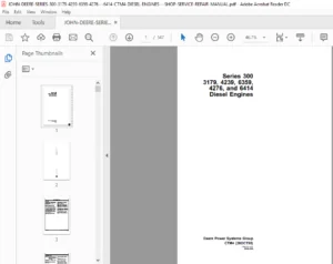
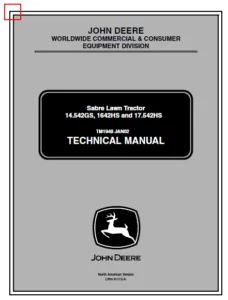
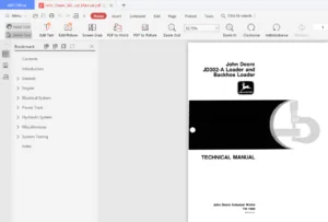
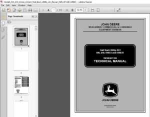
IMAGES PREVIEW OF THE MANUAL:
TABLE OF CONTENTS:
John Deere PowerTech 6068 OEM Diesel Engines (Final Tier 4Stage IV Platform) Component Technical Manual – PDF DOWNLOAD
Contents........................................................................................................................... 11 General Information............................................................................................................ 13 Safety..................................................................................................................... 15 Understand Signal Words................................................................................................ 15 Recognize Safety Information........................................................................................... 15 Replace Safety Signs................................................................................................... 15 Follow Safety Instructions............................................................................................. 16 California Proposition 65 Warning...................................................................................... 16 Exhaust Filter Cleaning................................................................................................ 16 Avoid Hot Exhaust...................................................................................................... 16 Work In Ventilated Area................................................................................................ 17 Decommissioning — Proper Recycling and Disposal of Fluids and Components............................................... 17 Prevent Machine Runaway................................................................................................ 18 Practice Safe Maintenance.............................................................................................. 18 Work in Clean Area..................................................................................................... 19 Wear Protective Clothing............................................................................................... 19 Service Machines Safely................................................................................................ 19 Use Proper Tools....................................................................................................... 20 Construct Dealer-Made Tools Safely..................................................................................... 20 Support Machine Properly............................................................................................... 20 Use Proper Lifting Equipment........................................................................................... 21 Protect Against Noise.................................................................................................. 21 Illuminate Work Area Safely............................................................................................ 21 Install All Guards..................................................................................................... 22 Stay Clear of Rotating Drivelines...................................................................................... 22 Protect Against High Pressure Spray.................................................................................... 22 Service Cooling System Safely.......................................................................................... 23 Remove Paint Before Welding or Heating................................................................................. 23 Precautions for Welding................................................................................................ 24 Wait Before Opening High-Pressure Fuel System.......................................................................... 24 Avoid High-Pressure Fluids............................................................................................. 25 Avoid Heating Near Pressurized Fluid Lines............................................................................. 25 Avoid Static Electricity Risk When Refueling........................................................................... 26 Handle Fluids Safely—Avoid Fires....................................................................................... 26 Prepare for Emergencies................................................................................................ 26 Handling Batteries Safely.............................................................................................. 27 Prevent Acid Burns..................................................................................................... 28 Prevent Battery Explosions............................................................................................. 28 Live With Safety....................................................................................................... 29 Engine Identification...................................................................................................... 31 Engine Serial Number Plate Information................................................................................. 31 OEM Engine Option Code Label........................................................................................... 32 Information Relative to Emissions Regulations.......................................................................... 32 Emissions Control System Certification Label........................................................................... 33 Fuels, Lubricants, and Coolant............................................................................................. 35 Diesel Exhaust Fluid (DEF) — Use in Selective Catalytic Reduction (SCR) Equipped Engines............................... 35 Storing Diesel Exhaust Fluid (DEF)..................................................................................... 35 Refilling Diesel Exhaust Fluid (DEF) Tank.............................................................................. 36 Testing Diesel Exhaust Fluid (DEF)..................................................................................... 37 Disposal of Diesel Exhaust Fluid (DEF)................................................................................. 37 Diesel Fuel............................................................................................................ 38 Supplemental Diesel Fuel Additives..................................................................................... 38 Lubricity of Diesel Fuel............................................................................................... 39 Handling and Storing Diesel Fuel....................................................................................... 39 BioDiesel Fuel......................................................................................................... 40 Testing Diesel Fuel.................................................................................................... 41 Fuel Filters........................................................................................................... 41 Minimizing the Effect of Cold Weather on Diesel Engines................................................................ 42 John Deere Break-In Plus™ Engine Oil — Interim Tier 4, Final Tier 4, Stage IIIB, and Stage IV.......................... 43 Diesel Engine Oil — Interim Tier 4, Final Tier 4, Stage IIIB, and Stage IV............................................. 43 Engine Oil and Filter Service Intervals — Interim Tier 4, Final Tier 4, Stage IIIB, and Stage IV — OEM Applications.... 44 Diesel Engine Oil and Filter Service Intervals......................................................................... 44 Mixing of Lubricants................................................................................................... 44 Alternative and Synthetic Lubricants................................................................................... 45 Lubricant Storage...................................................................................................... 45 Oil Filters............................................................................................................ 45 Diesel Engine Coolant (engine with wet sleeve cylinder liners)......................................................... 46 Water Quality for Mixing with Coolant Concentrate...................................................................... 47 Operating in Warm Temperature Climates................................................................................. 47 Testing Coolant Freeze Point........................................................................................... 48 Disposing of Coolant................................................................................................... 48 Repair and Adjustments......................................................................................................... 57 Engine Rebuild............................................................................................................. 59 Check and Service Cooling System....................................................................................... 59 Check Air Intake System................................................................................................ 59 Check Electrical System................................................................................................ 60 Check Exhaust System................................................................................................... 60 Clean Engine........................................................................................................... 61 Disconnect Turbocharger Oil Supply Line................................................................................ 62 Engine Assembly Sequence............................................................................................... 63 Engine Break-In Guidelines............................................................................................. 64 Engine Disassembly Sequence............................................................................................ 66 General Tune-Up Recommendations........................................................................................ 67 Engine Repair Stand.................................................................................................... 67 Install JT07268 Engine Mounting Adapter to D05223ST Repair Stand....................................................... 68 Install JDG11853 Engine Mounting Adapter to D05223ST Repair Stand...................................................... 68 Install Lift Straps.................................................................................................... 69 Lifting Procedure...................................................................................................... 71 Mount Engine to Repair Stand Using JT07268............................................................................. 72 Mount Engine to Repair Stand Using JDG11853............................................................................ 73 Engine Overhaul Guidelines............................................................................................. 74 Safety Precautions..................................................................................................... 74 Sealant Application Guidelines......................................................................................... 75 Cylinder Head and Valve Repair and Adjustment.............................................................................. 77 Cylinder Block Top Deck — Cleaning and Inspection...................................................................... 77 Cylinder Head — Cleaning and Inspection................................................................................ 77 Cylinder Head — Flatness Check......................................................................................... 77 Cylinder Head — Installation........................................................................................... 78 Cylinder Head — Removal................................................................................................ 81 Cylinder Head — Thickness Measurement.................................................................................. 82 Cylinder Head Gasket — Inspection...................................................................................... 83 Fuel Injector Sleeves — Installation................................................................................... 84 Fuel Injector Sleeves — Removal........................................................................................ 85 Glow Plug — Installation............................................................................................... 86 Glow Plug — Removal.................................................................................................... 87 Glow Plug Bore — Cleaning and Inspection............................................................................... 87 Glow Plug Heat Shield — Installation................................................................................... 88 Glow Plug Heat Shield — Removal........................................................................................ 89 Glow Plug Wiring Harness — Installation................................................................................ 91 Glow Plug Wiring Harness — Removal..................................................................................... 93 Crankcase Pressure Relief Valve — Maintenance.......................................................................... 95 Push Rod — Cleaning and Inspection..................................................................................... 96 Rocker Arm Carrier — Inspection........................................................................................ 96 Rocker Arm Cover — Inspection.......................................................................................... 96 Rocker Arm Cover — Installation........................................................................................ 97 Rocker Arm Cover — Removal............................................................................................. 99 Rocker Arm Cover Vent Tube — Inspection................................................................................ 100 Rocker Arm Shaft Assembly — Assemble................................................................................... 101 Rocker Arm Shaft Assembly — Inspection................................................................................. 104 Rocker Arm Shaft Carrier Assembly — Installation....................................................................... 105 Rocker Arm Shaft Carrier Assembly — Removal............................................................................ 108 Rocker Arm Shaft Assembly — Tear Down.................................................................................. 110 Valve — Cleaning and Inspection........................................................................................ 111 Valve — Clearance Adjustment........................................................................................... 112 Valve — Grinding....................................................................................................... 114 Valve — Measurement.................................................................................................... 115 Valve — Recess Measurement............................................................................................. 116 Valve Assembly — Installation.......................................................................................... 117 Valve Assembly — Removal............................................................................................... 119 Valve Bridges, Valve Retainer, and Valve Retainer Locks — Inspection................................................... 120 Valve Guide — Cleaning and Measurement................................................................................. 120 Valve Guide — Installation............................................................................................. 122 Valve Guide — Removal.................................................................................................. 123 Valve Seat — Cleaning and Inspection................................................................................... 123 Valve Seat — Grinding and Measurement.................................................................................. 124 Valve Seat Inserts — Installation...................................................................................... 125 Valve Seat Inserts — Removal........................................................................................... 126 Valve Spring — Inspection and Measurement.............................................................................. 127 Cylinder Block, Liners, Pistons, and Rods Repair and Adjustment............................................................ 129 Connecting Rod — Center-to-Center Bore Measurement..................................................................... 129 Connecting Rod and Cap — Inspection.................................................................................... 129 Connecting Rod Bearing — Inspection and Measurement.................................................................... 130 Connecting Rod Bearing — Inspection and Measurement (Rod and Crankshaft in Engine)..................................... 131 Connecting Rod Cap Screw — Torque Procedure............................................................................ 132 Connecting Rod Pin Bore — Cleaning and Inspection...................................................................... 133 Connecting Rod Piston Pin Bushing — Installation....................................................................... 133 Connecting Rod Piston Pin Bushing — Removal............................................................................ 134 Cylinder Block — Cleaning and Inspection............................................................................... 135 Cylinder Block Components — Measurement................................................................................ 139 Cylinder Block O-ring — Installation................................................................................... 140 Cylinder Block, Piston, and Rod — Troubleshooting Guide................................................................ 141 Cylinder Liner — Cleaning.............................................................................................. 141 Cylinder Liner Flange — Measurement.................................................................................... 142 Cylinder Liner — Installation.......................................................................................... 143 Cylinder Liner — Removal............................................................................................... 144 Cylinder Liner — Standout Measurement.................................................................................. 146 Cylinder Liner — Visual Inspection..................................................................................... 147 Cylinder Liner O-ring Bore — Cleaning.................................................................................. 148 Cylinder Liner Packing — Installation.................................................................................. 148 Piston — Cleaning...................................................................................................... 149 Piston — Inspection.................................................................................................... 149 Piston and Connecting Rod Assembly — Installation...................................................................... 150 Piston and Connecting Rod Assembly — Removal........................................................................... 151 Piston and Connecting Rod Assembly — Assemble.......................................................................... 152 Piston and Connecting Rod Assembly — Tear Down......................................................................... 153 Piston Spray Jet — Cleaning and Inspection............................................................................. 153 Piston Spray Jet — Installation........................................................................................ 154 Piston Spray Jet — Removal............................................................................................. 154 Piston Height — Measurement............................................................................................ 155 Piston Pin and Piston Pin Bore — Inspection............................................................................ 155 Piston Pin and Connecting Rod Bushing — Inspection..................................................................... 156 Piston Protrusion — Measurement........................................................................................ 157 Piston Rings — Installation............................................................................................ 158 Piston Skirt — Measurement............................................................................................. 159 Piston to Liner — Clearance Check...................................................................................... 160 Crankshaft, Main Bearings, Flywheel Repair, and Adjustment................................................................. 161 Crankshaft — End Play Check............................................................................................ 161 Crankshaft — Grinding Specs............................................................................................ 161 Crankshaft — Inspection................................................................................................ 162 Crankshaft — Installation.............................................................................................. 162 Crankshaft — Removal................................................................................................... 163 Crankshaft Gear — Installation......................................................................................... 164 Crankshaft Gear — Removal.............................................................................................. 165 Crankshaft Grinding — Guidelines....................................................................................... 165 Crankshaft Journals and Bearing Assembly — Measurement................................................................. 166 Crankshaft Main Bearing — Oil Clearance Check.......................................................................... 167 Crankshaft Main Bearing Cap — Line Bore Specs.......................................................................... 167 Crankshaft Main Bearing Caps — Installation............................................................................ 168 Crankshaft Main Bearing Caps — Removal................................................................................. 170 Crankshaft Rear Oil Seal — Installation................................................................................ 171 Crankshaft Rear Oil Seal — Removal..................................................................................... 172 Crankshaft Thrust Bearing — Inspection................................................................................. 173 Crankshaft Timing Wheel — Installation................................................................................. 174 Crankshaft Timing Wheel — Removal...................................................................................... 174 Crankshaft Unitized Front Oil Seal — Installation...................................................................... 175 Crankshaft Unitized Front Oil Seal — Removal........................................................................... 176 Crankshaft Unitized Rear Oil Seal — Installation....................................................................... 177 Crankshaft Unitized Rear Oil Seal — Removal............................................................................ 178 Crankshaft Vibration Damper — Inspection............................................................................... 179 Crankshaft Vibration Damper — Installation............................................................................. 181 Crankshaft Vibration Damper — Removal.................................................................................. 183 Crankshaft Viscous Damper — Inspection................................................................................. 184 Crankshaft Viscous Damper — Installation............................................................................... 185 Crankshaft Viscous Damper — Removal.................................................................................... 187 Flywheel — Inspection.................................................................................................. 188 Flywheel — Installation................................................................................................ 189 Flywheel — Removal..................................................................................................... 190 Flywheel Face — Flatness Check......................................................................................... 190 Flywheel Housing — Installation........................................................................................ 191 Flywheel Housing — Removal............................................................................................. 194 Flywheel Pilot Bearing Bore — Concentricity Check...................................................................... 195 Flywheel Ring Gear — Installation...................................................................................... 195 Flywheel Ring Gear — Removal........................................................................................... 196 Open Crankcase Ventilation System — Inspection......................................................................... 196 Open Crankcase Ventilation System — Installation (Standard System)..................................................... 197 Open Crankcase Ventilation System — Removal (Standard System).......................................................... 199 Open Crankcase Ventilation System — Installation (High Capacity System)................................................ 201 Open Crankcase Ventilation System — Removal (High Capacity System)..................................................... 202 Camshaft and Timing Gear Train Repair and Adjustment....................................................................... 203 Camshaft — Check End Play.............................................................................................. 203 Camshaft — Inspection.................................................................................................. 203 Camshaft — Installation................................................................................................ 204 Camshaft — Removal..................................................................................................... 205 Camshaft Bushing — Installation........................................................................................ 206 Camshaft Bushing Journal #1 — Measurement.............................................................................. 206 Camshaft Bushing — Removal............................................................................................. 207 Camshaft and Upper Idler Gear — Timing................................................................................. 208 Camshaft Follower — Inspection and Measurement......................................................................... 210 Camshaft Follower — Installation....................................................................................... 211 Camshaft Follower — Removal............................................................................................ 211 Camshaft Gear — Inspection............................................................................................. 212 Camshaft Gear — Installation........................................................................................... 212 Camshaft Gear — Removal................................................................................................ 212 Camshaft Gear-Driven Auxiliary Drive — Installation.................................................................... 213 Camshaft Gear-Driven Auxiliary Drive — Removal......................................................................... 214 Camshaft Journal — Measurement......................................................................................... 215 Camshaft Lobe — Lift Measurement....................................................................................... 215 Camshaft Thrust Plate — Measure Clearance and Thickness................................................................ 216 Front Plate — Installation............................................................................................. 217 Front Plate — Removal.................................................................................................. 219 Idler Gears — Measure End Play......................................................................................... 220 Lower Idler Gear — Inspection.......................................................................................... 220 Lower Idler Gear — Installation........................................................................................ 221 Lower Idler Gear — Removal............................................................................................. 221 Timing Gear Cover — Installation....................................................................................... 222 Timing Gear Cover — Removal............................................................................................ 224 Timing Gears — Check Backlash.......................................................................................... 225 Upper Idler Gear — Inspection.......................................................................................... 226 Upper Idler Gear — Installation........................................................................................ 226 Upper Idler Gear — Removal............................................................................................. 227 Lubrication System Repair and Adjustment................................................................................... 229 Dipstick Tube and Dipstick — Inspection................................................................................ 229 Dipstick Tube and Dipstick — Installation.............................................................................. 230 Dipstick Tube and Dipstick — Removal................................................................................... 231 Oil Cooler — Inspection................................................................................................ 232 Oil Cooler — Installation.............................................................................................. 232 Oil Cooler — Removal................................................................................................... 234 Oil Filter — Changing.................................................................................................. 235 Oil Filter Header — Installation....................................................................................... 235 Oil Filter Header — Removal............................................................................................ 237 Oil Filter Bypass Valve — Installation................................................................................. 238 Oil Filter Bypass Valve — Removal...................................................................................... 238 Oil Pan — Installation................................................................................................. 239 Oil Pan — Removal...................................................................................................... 242 Oil Pick-Up Tube — Installation........................................................................................ 244 Oil Pick-Up Tube — Removal............................................................................................. 244 Oil Pressure Regulating Valve — Installation........................................................................... 245 Oil Pressure Regulating Valve — Removal and Inspection................................................................. 246 Oil Pump — Installation................................................................................................ 247 Oil Pump — Removal..................................................................................................... 249 Cooling System Repair and Adjustment....................................................................................... 253 Belt — Wear Check...................................................................................................... 253 Belt Tensioner — Installation.......................................................................................... 253 Belt Tensioner — Removal............................................................................................... 254 Belt Tensioner — Spring Tension Check.................................................................................. 255 Coolant Manifold Assembly — Installation............................................................................... 255 Coolant Manifold Assembly — Removal.................................................................................... 256 Coolant Pump Assembly — Inspection..................................................................................... 256 Coolant Pump Assembly — Installation................................................................................... 258 Coolant Pump Assembly — Removal........................................................................................ 260 Coolant Pump Inlet Elbow — Installation................................................................................ 261 Coolant Pump Inlet Elbow — Removal..................................................................................... 261 Cooling System — Air Bleeding.......................................................................................... 262 Fan (Fixed Speed Fan) — Inspection and Installation.................................................................... 263 Fan (Fixed Speed Fan) — Removal........................................................................................ 263 Fan (Variable Speed Fan) — Inspection and Installation................................................................. 264 Fan (Variable Speed Fan) — Removal..................................................................................... 266 Fan Drive Adapter — Installation....................................................................................... 267 Fan Drive Adapter — Removal............................................................................................ 267 Fan Drive Assembly — Assemble.......................................................................................... 268 Fan Drive Assembly — Installation...................................................................................... 269 Fan Drive Assembly — Removal........................................................................................... 275 Fan Drive Pulley — Installation........................................................................................ 277 Fan Drive Pulley — Removal............................................................................................. 278 Thermostat — Installation.............................................................................................. 278 Thermostat — Removal................................................................................................... 281 Thermostat Housing — Assemble.......................................................................................... 282 Thermostat Housing — Removal........................................................................................... 287 Thermostat Housing — Tear Down......................................................................................... 288 Air Intake and Exhaust System Repair and Adjustment - Dual Turbocharger.................................................... 289 Air Inlet — Installation (High Capacity OCV)........................................................................... 289 Air Inlet — Removal (High Capacity OCV)................................................................................ 291 EGR Cooler Straps (Dual Turbocharger) — Installation................................................................... 291 EGR Cooler Straps (Dual Turbocharger) — Removal........................................................................ 292 EGR Cooler Assembly (Dual Turbocharger) — Installation................................................................. 292 EGR Cooler Assembly (Dual Turbocharger) — Removal...................................................................... 292 EGR Cooler Bracket — Installation...................................................................................... 293 EGR Cooler Bracket — Removal........................................................................................... 297 EGR Cooler Coolant Return Line (Dual Turbocharger) — Installation...................................................... 300 EGR Cooler Coolant Return Line (Dual Turbocharger) — Removal........................................................... 301 EGR Cooler Coolant Supply Line (Dual Turbocharger) — Installation...................................................... 301 EGR Cooler Coolant Supply Line (Dual Turbocharger) — Removal........................................................... 302 EGR Cooler Gas Inlet Pipe (Dual Turbocharger) — Installation........................................................... 303 EGR Cooler Gas Inlet Pipe (Dual Turbocharger) — Removal................................................................ 304 EGR Cooler Gas Outlet Pipe (Dual Turbocharger) — Installation.......................................................... 305 EGR Cooler Gas Outlet Pipe (Dual Turbocharger) — Removal............................................................... 306 EGR Flow Venturi Assembly (Dual Turbocharger) — Installation........................................................... 306 EGR Flow Venturi Assembly (Dual Turbocharger) — Removal................................................................ 307 EGR Flow Venturi Coolant Return Line (Dual Turbocharger) — Installation................................................ 308 EGR Flow Venturi Coolant Return Line (Dual Turbocharger) — Removal..................................................... 309 EGR Flow Venturi Coolant Supply Line (Dual Turbocharger) — Installation................................................ 309 EGR Flow Venturi Coolant Supply Line (Dual Turbocharger) — Removal..................................................... 310 EGR Flow Venturi Inlet Pipe (Dual Turbocharger) — Installation......................................................... 310 EGR Flow Venturi Inlet Pipe (Dual Turbocharger) — Removal.............................................................. 311 EGR Valve Bracket (Dual Turbocharger) — Installation................................................................... 311 EGR Valve Bracket (Dual Turbocharger) — Removal........................................................................ 312 Exhaust Gas Recirculation (Dual Turbocharger) — Component View......................................................... 313 Exhaust Manifold (Dual Turbocharger) — Installation.................................................................... 314 Exhaust Manifold (Dual Turbocharger) — Removal and Inspection.......................................................... 316 Sliding Element Bracket — Installation................................................................................. 316 Sliding Element Bracket — Removal...................................................................................... 323 Extending Turbocharger Life (Dual Turbocharger)........................................................................ 326 Fixed Turbocharger Oil Drain Line (Dual Turbocharger) — Installation................................................... 327 Fixed Turbocharger Oil Drain Line (Dual Turbocharger) — Removal........................................................ 330 Intake Manifold (Dual Turbocharger) — Installation..................................................................... 331 Intake Manifold (Dual Turbocharger) — Removal and Inspection........................................................... 332 Turbocharger (Dual Turbocharger) — Break-In............................................................................ 332 Turbocharger (Dual Turbocharger) — Failure Analysis.................................................................... 333 Turbocharger (Dual Turbocharger) — Inspection.......................................................................... 335 Turbocharger Compression Housing (Dual Turbocharger) — Orientation..................................................... 339 Turbocharger Compressor Interstage (Dual Turbocharger) — Installation.................................................. 340 Turbocharger Compressor Interstage (Dual Turbocharger) — Removal....................................................... 343 Turbocharger Coolant Supply Line and Return Line (Dual Turbocharger) — Installation.................................... 346 Turbocharger Coolant Supply Line and Return Line (Dual Turbocharger) — Removal......................................... 348 Turbocharger, Fixed (Dual Turbocharger) — Installation................................................................. 350 Turbocharger, Fixed (Dual Turbocharger) — Removal...................................................................... 352 Turbocharger Oil Supply Lines (Dual Turbocharger) — Installation....................................................... 353 Turbocharger Oil Supply Lines (Dual Turbocharger) — Removal............................................................ 356 Turbocharger Turbine Interstage (Dual Turbocharger) — Installation..................................................... 359 Turbocharger Turbine Interstage (Dual Turbocharger) — Removal.......................................................... 360 Turbocharger VGT Adjustment Ring — Installation........................................................................ 360 Turbocharger VGT Adjustment Ring — Removal............................................................................. 364 Turbocharger, VGT (Dual Turbocharger) — Installation................................................................... 367 Turbocharger, VGT (Dual Turbocharger) — Removal........................................................................ 368 VGT Actuator (Dual Turbocharger) — Installation........................................................................ 369 VGT Actuator (Dual Turbocharger) — Removal............................................................................. 369 VGT Actuator Linkage (Dual Turbocharger) — Installation................................................................ 370 VGT Actuator Linkage (Dual Turbocharger) — Removal..................................................................... 371 VGT Oil Drain Line (Dual Turbocharger) — Installation.................................................................. 372 VGT Oil Drain Line (Dual Turbocharger) — Removal....................................................................... 374 VGT Speed Sensor (Dual Turbocharger) — Installation.................................................................... 376 VGT Speed Sensor (Dual Turbocharger) — Removal......................................................................... 376 Air Intake and Exhaust System Repair and Adjustment - Single Turbocharger.................................................. 377 Air Inlet — Installation (Standard Capacity OCV)....................................................................... 377 Air Inlet — Removal (Standard Capacity OCV)............................................................................ 378 EGR Cooler Assembly (Single Turbocharger) — Installation............................................................... 379 EGR Cooler Assembly (Single Turbocharger) — Removal.................................................................... 380 EGR Cooler Coolant Return Line (Single Turbocharger) — Installation.................................................... 381 EGR Cooler Coolant Return Line (Single Turbocharger) — Removal......................................................... 381 EGR Cooler Coolant Supply Line (Single Turbocharger) — Installation.................................................... 381 EGR Cooler Coolant Supply Line (Single Turbocharger) — Removal......................................................... 381 EGR Cooler Gas Inlet Pipe (Single Turbocharger) — Installation......................................................... 382 EGR Cooler Gas Inlet Pipe (Single Turbocharger) — Removal.............................................................. 383 EGR Cooler Gas Outlet Pipe (Single Turbocharger) — Installation........................................................ 384 EGR Cooler Gas Outlet Pipe (Single Turbocharger) — Removal............................................................. 385 EGR Flow Venturi Assembly (Single Turbocharger) — Installation......................................................... 385 EGR Flow Venturi Assembly (Single Turbocharger) — Removal.............................................................. 385 EGR Flow Venturi Coolant Return Line (Single Turbocharger) — Installation.............................................. 386 EGR Flow Venturi Coolant Return Line (Single Turbocharger) — Removal................................................... 387 EGR Flow Venturi Coolant Supply Line (Single Turbocharger) — Installation.............................................. 387 EGR Flow Venturi Coolant Supply Line (Single Turbocharger) — Removal................................................... 387 EGR Flow Venturi Inlet Pipe (Single Turbocharger) — Installation....................................................... 388 EGR Flow Venturi Inlet Pipe (Single Turbocharger) — Removal............................................................ 388 Exhaust Gas Recirculation (Single Turbocharger) — Component View....................................................... 388 Exhaust Manifold (Single Turbocharger) — Installation.................................................................. 389 Exhaust Manifold (Single Turbocharger) — Removal and Inspection........................................................ 389 Extending Turbocharger Life (Single Turbocharger)...................................................................... 390 Intake Manifold (Single Turbocharger) — Installation................................................................... 391 Intake Manifold (Single Turbocharger) — Removal and Inspection......................................................... 391 Turbocharger (Single Turbocharger) — Break-In.......................................................................... 391 Turbocharger (Single Turbocharger) — Failure Analysis.................................................................. 392 Turbocharger (Single Turbocharger) — Inspection........................................................................ 394 Turbocharger Compression Housing (Single Turbocharger) — Orientation................................................... 398 VGT Actuator (Single Turbocharger) — Installation...................................................................... 399 VGT Actuator (Single Turbocharger) — Removal........................................................................... 399 VGT Actuator Linkage (Single Turbocharger) — Installation.............................................................. 399 VGT Actuator Linkage (Single Turbocharger) — Removal................................................................... 399 VGT Coolant Supply Line and Return Line (Single Turbocharger) — Installation........................................... 400 VGT Coolant Supply Line and Return Line (Single Turbocharger) — Removal................................................ 402 VGT Oil Drain Line (Single Turbocharger) — Installation................................................................ 404 VGT Oil Drain Line (Single Turbocharger) — Removal..................................................................... 406 VGT Speed Sensor (Single Turbocharger) — Installation.................................................................. 407 VGT Speed Sensor (Single Turbocharger) — Removal....................................................................... 410 VGT Turbocharger Assembly (Single Turbocharger) — Installation......................................................... 411 VGT Turbocharger Assembly (Single Turbocharger) — Removal.............................................................. 412 VGT Turbocharger Oil Supply Lines (Single Turbocharger) — Installation................................................. 413 VGT Turbocharger Oil Supply Lines (Single Turbocharger) — Removal...................................................... 414 Electronic Fuel System Repair and Adjustment............................................................................... 415 EGR Cooler Bracket — Fuel Component Assembly........................................................................... 415 Electronic Injectors — Cleaning (In Engine)............................................................................ 416 Electronic Injectors — Installation.................................................................................... 417 Electronic Injectors — Removal......................................................................................... 418 Flow Dampers — Installation............................................................................................ 419 Flow Dampers — Removal................................................................................................. 420 Fuel Filter Bracket — Installation..................................................................................... 421 Fuel Filter Bracket — Removal.......................................................................................... 422 Fuel Filter Elements — Replacement..................................................................................... 424 Fuel Rail Pressure Relief Valve — Installation......................................................................... 427 Fuel Rail Pressure Relief Valve — Removal.............................................................................. 428 High-Pressure Common-Rail (HPCR) — Installation........................................................................ 429 High-Pressure Common-Rail (HPCR) — Removal............................................................................. 430 High-Pressure Fuel Pump — Disassembly.................................................................................. 431 High-Pressure Fuel Pump — Assemble..................................................................................... 433 High-Pressure Fuel Pump — Installation................................................................................. 437 High-Pressure Fuel Pump — Removal...................................................................................... 442 High-Pressure Injection Lines and Feed Tubes — Installation............................................................ 446 High-Pressure Injection Lines and Feed Tubes — Removal................................................................. 448 Injector Wiring Harness — Installation................................................................................. 450 Injector Wiring Harness — Removal...................................................................................... 451 Low-Pressure Fuel Pump — Installation.................................................................................. 451 Low-Pressure Fuel Pump — Removal....................................................................................... 452 Primary Fuel Filter Assembly — Installation............................................................................ 452 Primary Fuel Filter Assembly — Removal................................................................................. 454 Secondary Fuel Filter Assembly — Installation......................................................................... 456 Secondary Fuel Filter Assembly — Removal............................................................................... 460 OEM Starting and Charging Systems Repair and Adjustment.................................................................... 463 Alternator — Installation.............................................................................................. 463 Alternator — Removal................................................................................................... 465 Starter Motor — Installation........................................................................................... 467 Starter Motor — Removal................................................................................................ 468 Electrical Engine Control Repair and Adjustment............................................................................ 469 Aftertreatment Inlet NOx Sensor — Installation......................................................................... 469 Aftertreatment Inlet NOx Sensor — Removal.............................................................................. 469 Aftertreatment Outlet NOx Sensor — Installation........................................................................ 470 Aftertreatment Outlet NOx Sensor — Removal............................................................................. 470 Air Throttle Actuator — Installation................................................................................... 471 Air Throttle Actuator — Removal........................................................................................ 472 Camshaft Position Sensor — Installation................................................................................ 473 Camshaft Position Sensor — Removal..................................................................................... 473 Charge Air Cooler Outlet Temperature Sensor — Installation............................................................. 474 Charge Air Cooler Outlet Temperature Sensor — Removal.................................................................. 475 Crankshaft Position Sensor — Installation.............................................................................. 476 Crankshaft Position Sensor — Removal................................................................................... 477 DPF Differential Pressure Sensor — Installation........................................................................ 478 DPF Differential Pressure Sensor — Removal............................................................................. 479 EGR Flow Sensor — Installation......................................................................................... 480 EGR Flow Sensor — Removal.............................................................................................. 481 EGR Temperature Sensor — Installation.................................................................................. 482 EGR Temperature Sensor — Removal....................................................................................... 483 EGR Valve — Installation............................................................................................... 484 EGR Valve — Removal.................................................................................................... 487 Engine Control Unit (ECU) — Installation............................................................................... 489 Engine Control Unit (ECU) — Maintenance................................................................................ 490 Engine Control Unit (ECU) — Removal.................................................................................... 491 Engine Coolant Pressure Sensor — Installation.......................................................................... 493 Engine Coolant Pressure Sensor — Removal............................................................................... 494 Engine Coolant Temperature Sensor — Installation....................................................................... 495 Engine Coolant Temperature Sensor — Removal............................................................................ 496 Engine Crankcase Pressure Sensor — Installation........................................................................ 497 Engine Crankcase Pressure Sensor — Removal............................................................................. 498 Engine Oil Pressure Sensor — Installation.............................................................................. 499 Engine Oil Pressure Sensor — Removal................................................................................... 500 Aftertreatment Temperature Module — Installation....................................................................... 501 Aftertreatment Temperature Module — Removal............................................................................ 502 Exhaust Manifold Pressure Sensor — Installation........................................................................ 503 Exhaust Manifold Pressure Sensor — Removal............................................................................. 506 Fixed Turbocharger Compressor Outlet Temperature Sensor — Installation................................................. 509 Fixed Turbocharger Compressor Outlet Temperature Sensor — Removal...................................................... 510 Fuel Rail Pressure Relief Valve Solenoid — Installation................................................................ 511 Fuel Rail Pressure Relief Valve Solenoid — Removal..................................................................... 511 Fuel Rail Pressure Sensor — Installation............................................................................... 512 Fuel Rail Pressure Sensor — Removal.................................................................................... 514 Fuel Temperature Sensor — Installation................................................................................. 515 Fuel Temperature Sensor — Removal...................................................................................... 516 Intake Air Sensor — Installation....................................................................................... 517 Intake Air Sensor — Removal............................................................................................ 517 Intake Manifold Air Pressure (MAP) Sensor — Installation............................................................... 518 Intake Manifold Air Pressure (MAP) Sensor — Removal.................................................................... 519 Intake Manifold Air Temperature (MAT) Sensor — Installation............................................................ 520 Intake Manifold Air Temperature (MAT) Sensor — Removal................................................................. 521 Low-Pressure Fuel Pressure Sensor — Installation....................................................................... 522 Low-Pressure Fuel Pressure Sensor — Removal............................................................................ 523 Pressure Control Valve Solenoid — Installation......................................................................... 524 Pressure Control Valve Solenoid — Removal.............................................................................. 526 SCR Temperature Module — Installation.................................................................................. 528 SCR Temperature Module — Removal....................................................................................... 529 VGT Speed Sensor — Installation........................................................................................ 530 VGT Speed Sensor — Removal............................................................................................. 533 Water-In-Fuel (WIF) Sensor — Installation.............................................................................. 533 Water-In-Fuel (WIF) Sensor — Removal................................................................................... 534 Wiring Harness — Installation.......................................................................................... 535 Wiring Harness — Removal............................................................................................... 544 Wiring Harness — Routing............................................................................................... 553 Connector Repair and Adjustment............................................................................................ 555 Connectors............................................................................................................. 555 Installation of Repair Wire Assembly (RWA)............................................................................. 555 Repair AMP® Seal 16 - Type “A” Connectors.............................................................................. 559 Repair AMP® Seal 16 - Type “B” Connectors.............................................................................. 560 Repair AMP® Seal 16 - Type “C” Connectors.............................................................................. 562 Repair Bosch Connectors................................................................................................ 563 Repair DEUTSCH Connectors.............................................................................................. 563 Repair Metri-Pack™ Connectors.......................................................................................... 566 Repair Tyco HDSCS Connectors........................................................................................... 566 Repair WEATHER PACK® Connectors........................................................................................ 568 Using High-Pressure Washing............................................................................................ 568 Fuel Dosing Aftertreatment Devices Repair and Adjustment................................................................... 569 Diesel Particulate Filter Maintenance and Service...................................................................... 569 Diesel Oxidation Catalyst (DOC) — Cleaning............................................................................. 570 DPF Differential Pressure Sensor Manifold Fittings— Installation....................................................... 571 DPF Differential Pressure Sensor Manifold Fittings— Removal............................................................ 572 Exhaust Filter — Assemble.............................................................................................. 573 Exhaust Filter — Cleaning.............................................................................................. 574 Exhaust Filter — Diesel Particulate Filter Ash Handling and Disposal................................................... 574 Exhaust Filter — Disposal.............................................................................................. 574 Exhaust Filter — Handling.............................................................................................. 575 Exhaust Filter — Tear Down and Inspection.............................................................................. 576 Exhaust Filter, Brackets, and Piping — Installation.................................................................... 581 Exhaust Filter, Brackets and Piping — Removal.......................................................................... 582 DEF Dosing Aftertreatment Devices Repair and Adjustment.................................................................... 585 DEF Decomposition Tube — Cleaning...................................................................................... 585 DEF Decomposition Tube — Installation.................................................................................. 585 DEF Decomposition Tube — Removal....................................................................................... 587 DEF Dosing Injector — Cleaning......................................................................................... 587 DEF Dosing Injector — Installation..................................................................................... 588 DEF Dosing Injector — Removal.......................................................................................... 589 DEF Dosing System Coolant Filter— Installation......................................................................... 589 DEF Dosing System Coolant Filter — Removal............................................................................. 589 DEF Dosing System Coolant Lines — Installation......................................................................... 589 DEF Dosing System Coolant Lines — Removal.............................................................................. 589 DEF Dosing System Lines — Installation................................................................................. 590 DEF Dosing System Lines — Removal...................................................................................... 593 DEF Dosing Unit — Installation......................................................................................... 594 DEF Dosing Unit — Removal.............................................................................................. 594 DEF Dosing Unit Filter — Installation.................................................................................. 595 DEF Dosing Unit Filter — Removal....................................................................................... 596 DEF Dosing Unit Fittings — Installation................................................................................ 597 DEF Dosing Unit Fittings — Removal..................................................................................... 597 DEF Tank Header Assembly — Installation................................................................................ 598 DEF Tank Header Assembly — Removal..................................................................................... 599 DEF Tank Header Assembly (CAN Based) — Installation.................................................................... 600 DEF Tank Header Assembly (CAN Based) — Removal......................................................................... 601 DEF Tank Header Coolant Control Valve and Fitting (CAN Based) — Installation........................................... 602 DEF Tank Header Coolant Control Valve and Fitting (CAN Based) — Removal................................................ 603 DEF Tank Header Fittings (CAN Based) — Installation.................................................................... 603 DEF Tank Header Fittings (CAN Based) — Removal......................................................................... 604 DEF Tank Header Suction Screen (CAN Based) — Installation.............................................................. 605 DEF Tank Header Suction Screen (CAN Based) — Removal................................................................... 605 DEF Tank Header Suction Screen — Installation.......................................................................... 606 DEF Tank Header Suction Screen — Removal............................................................................... 606 DEF Tank Heater Coolant Control Valve Solenoid — Installation.......................................................... 607 DEF Tank Heater Coolant Control Valve Solenoid — Removal............................................................... 608 Selective Catalyst Reduction (SCR) — Cleaning and Inspection........................................................... 609 Selective Catalyst Reduction (SCR) — Handling.......................................................................... 609 Selective Catalyst Reduction (SCR), Brackets and Piping — Installation................................................. 610 Selective Catalyst Reduction (SCR), Brackets and Piping — Removal...................................................... 612 Theory of Operation............................................................................................................ 616 PowerTech PSS Base Engine Operation........................................................................................ 617 Engine Sectional View Component Location Diagrams...................................................................... 617 General Engine Operation............................................................................................... 618 General Engine Operation — Continue.................................................................................... 619 Head Gasket Joint Construction and Operation........................................................................... 620 Cooling System............................................................................................................. 621 Cooling System Component Location Diagram.............................................................................. 621 Cooling System Operation............................................................................................... 622 Lubrication System......................................................................................................... 623 Lubrication System Component Location Diagram.......................................................................... 623 Lubrication System Operation........................................................................................... 624 Electronic Fuel System..................................................................................................... 625 Fuel System Schematic.................................................................................................. 625 Electronic Fuel System Component Location Diagram 1.................................................................... 626 Electronic Fuel System Component Location Diagram 2.................................................................... 627 Electronic Fuel System Component Location Diagram 3.................................................................... 627 Electronic Fuel System Component Location Diagram 4.................................................................... 628 Electric Low-Pressure Fuel Pump Operation.............................................................................. 628 Electric Low-Pressure Fuel System Operation............................................................................ 629 Primary and Secondary Fuel Filter Operation............................................................................ 631 Electronic Injector (EI) Operation..................................................................................... 633 High-Pressure Common Rail (HPCR) Operation............................................................................. 635 High-Pressure Fuel Pump Operation...................................................................................... 636 High-Pressure Fuel System Operation.................................................................................... 637 Pilot Injection Operation.............................................................................................. 638 Air Intake and Exhaust System.............................................................................................. 639 Air Intake and Exhaust System Operation................................................................................ 639 Air Throttle Actuator Operation........................................................................................ 641 Cold Start Aid Operation............................................................................................... 642 Air Intake and Exhaust System Component Location Diagram 1............................................................. 643 Air Intake and Exhaust System Component Location Diagram 2............................................................. 643 Air Intake and Exhaust System Component Location Diagram 3............................................................. 644 Air Intake and Exhaust System Component Location Diagram 4............................................................. 644 EGR Cooler Operation................................................................................................... 644 EGR Valve Operation.................................................................................................... 645 Fixed Turbocharger Operation........................................................................................... 645 VGT Operation.......................................................................................................... 646 Aftertreatment System...................................................................................................... 647 Aftertreatment System Operation........................................................................................ 647 Component Location Diagram 1........................................................................................... 647 Component Location Diagram 2........................................................................................... 648 Exhaust Filter Operation............................................................................................... 649 DEF Dosing Injector Operation.......................................................................................... 652 DEF Dosing Unit Operation.............................................................................................. 653 DEF Tank Header (CAN Based) Operation.................................................................................. 654 DEF Tank Header Operation.............................................................................................. 655 Regeneration — Engines without DPF..................................................................................... 656 SCR Operation.......................................................................................................... 657 SCR System Derates..................................................................................................... 658 Electrical Control System.................................................................................................. 659 Electrical Engine Control Component Location Diagram 1................................................................. 659 Electrical Engine Control Component Location Diagram 2................................................................. 660 Electrical Engine Control Component Location Diagram 3................................................................. 661 Electrical Engine Control Component Location Diagram 4................................................................. 662 Electrical Engine Control Component Location Diagram 5................................................................. 663 Electrical Engine Control Component Location Diagram 6................................................................. 664 Electrical Engine Control Component Location Diagram 7................................................................. 665 Analog Throttle........................................................................................................ 666 A5507 — DEF Tank Header Assembly Connector............................................................................. 666 B5009 — Engine Coolant Level Alarm Switch.............................................................................. 667 B5010 — Engine Coolant Level Information Switch........................................................................ 668 B5101 — Engine Oil Pressure Sensor..................................................................................... 669 B5102 — Exhaust Manifold Pressure Sensor............................................................................... 671 B5103 — EGR Flow Sensor................................................................................................ 673 B5104 — Manifold Air Pressure Sensor................................................................................... 675 B5105 — Engine Crankcase Pressure Sensor............................................................................... 677 B5107 — Low-Pressure Fuel Pressure Sensor.............................................................................. 679 B5108 — Engine Coolant Pressure Sensor................................................................................. 681 B5109 — DPF Differential Pressure Sensor............................................................................... 683 B5113 — Fuel Rail Pressure Sensor...................................................................................... 683 B5200 — Fixed Turbocharger Compressor Outlet Temperature Sensor........................................................ 685 B5204 — Aftertreatment Temperature Module.............................................................................. 687 B5205 — Charge Air Cooler Outlet Temperature Sensor.................................................................... 688 B5206 — Manifold Air Temperature Sensor................................................................................ 690 B5207 — EGR Temperature Sensor......................................................................................... 692 B5208 — Engine Coolant Temperature Sensor.............................................................................. 694 B5209 — Fuel Temperature Sensor........................................................................................ 696 B5212 — SCR Temperature Module......................................................................................... 698 B5300 — VGT Speed Sensor............................................................................................... 698 B5301 — Crankshaft Position Sensor..................................................................................... 700 B5302 — Camshaft Position Sensor....................................................................................... 702 B5500 — Intake Air Sensor.............................................................................................. 704 B5501 — DEF Dosing Unit................................................................................................ 706 B5502 — Aftertreatment Inlet NOx Sensor................................................................................ 706 B5506 — DEF Tank Header Assembly Connector (CAN Based)................................................................. 707 B5503 — Aftertreatment Outlet NOx Sensor............................................................................... 707 B5600 — Water-In-Fuel Sensor........................................................................................... 708 Barometric Air Pressure Sensor......................................................................................... 709 Combination Throttle................................................................................................... 710 Controller Area Network (CAN).......................................................................................... 710 Cruise Control Operation............................................................................................... 711 Digital Throttle....................................................................................................... 712 E5601 — DEF Dosing Unit Pressure Line Heater........................................................................... 713 E5602 — DEF Dosing Unit Supply Line Heater............................................................................. 713 E5603 — DEF Dosing Unit Return Line Heater............................................................................. 713 Engine Control Unit (ECU) System Operation............................................................................. 714 Engine Control Unit Temperature Sensor................................................................................. 715 Engine Derate and Shutdown Protection.................................................................................. 716 Governor Droop Mode Selection.......................................................................................... 717 Measuring Pressure..................................................................................................... 718 Measuring Speed........................................................................................................ 718 Measuring Temperature.................................................................................................. 719 Sensor Supply #1....................................................................................................... 720 Sensor Supply #2....................................................................................................... 720 Sensor Supply #3....................................................................................................... 720 Sensor Supply #4....................................................................................................... 720 Sensor Supply #5....................................................................................................... 720 Sensor Supply #6....................................................................................................... 721 Sensor Supply #7....................................................................................................... 721 Sensor Supply #8....................................................................................................... 721 Sensor Supply #9....................................................................................................... 721 Sensor Supply #10...................................................................................................... 721 Throttle Adjustments................................................................................................... 722 Throttle Offset........................................................................................................ 722 Throttle Self-Calibration.............................................................................................. 723 Torque Speed Control (TSC)............................................................................................. 723 Y5004 — Low-Pressure Fuel Pump (2 pin connector)....................................................................... 724 Y5014 — Fan Solenoid - Increase........................................................................................ 724 Y5015 — Fan Solenoid - Decrease........................................................................................ 724 Y5018 — Ether Control Solenoid......................................................................................... 724 Y5019 — DEF Tank Heater Coolant Control Valve.......................................................................... 725 Y5020 — DEF Dosing Injector............................................................................................ 725 Y5021 — Fuel Injector Harness.......................................................................................... 725 Y5022 — Pressure Control Valve 1....................................................................................... 726 Y5023 — Pressure Control Valve 2....................................................................................... 728 Y5024 — Pressure Relief Valve.......................................................................................... 730 Y5400 — EGR Valve...................................................................................................... 732 Y5401 — Air Throttle Actuator.......................................................................................... 734 Y5500 — VGT Actuator................................................................................................... 736 Y5501 — Low-Pressure Fuel Pump......................................................................................... 738 Diagnostics.................................................................................................................... 759 Observable Diagnostics..................................................................................................... 761 Abnormal Engine Noise.................................................................................................. 761 Coolant in Oil or Oil in Coolant....................................................................................... 763 ECU Does Not Communicate with Powerview................................................................................ 764 Diagnostic Procedure............................................................................................... 764 ECU Does Not Communicate with Service ADVISOR.......................................................................... 767 Diagnostic Procedure............................................................................................... 768 ECU Does Not Program with Service ADVISOR.............................................................................. 773 Diagnostic Procedure............................................................................................... 773 Engine Coolant Temperature Below Normal................................................................................ 774 Diagnostic Procedure............................................................................................... 774 Engine Cranks and Will Not Start....................................................................................... 777 Diagnostic Procedure............................................................................................... 777 Engine Does Not Develop Full Power..................................................................................... 783 Diagnostic Procedure............................................................................................... 783 Engine Emits Excessive Black or Gray Exhaust Smoke..................................................................... 788 Engine Emits Excessive Black or Gray Exhaust Smoke Diagnostic Procedure............................................ 788 Engine Emits Excessive Blue Exhaust Smoke.............................................................................. 788 Engine Emits Excessive Blue Exhaust Smoke Diagnostic Procedure..................................................... 788 Engine Emits Excessive White Exhaust Smoke............................................................................. 789 Engine Emits Excessive White Exhaust Smoke Diagnostic Procedure.................................................... 789 Engine Misfires or Runs Irregularly.................................................................................... 790 Diagnostic Procedure............................................................................................... 790 Engine Will Not Crank.................................................................................................. 795 Diagnostic Procedure............................................................................................... 795 Excessive DEF Consumption.............................................................................................. 798 Diagnostic Procedure............................................................................................... 798 Excessive Fuel Consumption............................................................................................. 800 Excessive Oil Carryover................................................................................................ 801 Diagnostic Procedure............................................................................................... 801 Excessive Oil Consumption.............................................................................................. 802 Diagnostic Procedure............................................................................................... 802 Frequent Regenerations................................................................................................. 804 Fuel in Coolant........................................................................................................ 805 Diagnostic Procedure............................................................................................... 805 Fuel in Oil............................................................................................................ 806 Diagnostic Procedure............................................................................................... 806 JDLink Does Not Communicate with ECU................................................................................... 810 Throttle Not Responding................................................................................................ 811 Diagnostic Procedure............................................................................................... 811 Checks, Tests, and Procedures.............................................................................................. 813 Aftertreatment CAN Diagnostic Procedure................................................................................ 813 Diagnostic Procedure............................................................................................... 814 Aftertreatment Verification Procedure.................................................................................. 821 Air in Fuel Check...................................................................................................... 822 Diagnostic Procedure............................................................................................... 822 CAN Message Not Received............................................................................................... 824 CAN Message Received Error............................................................................................. 825 CAN Message Received Is Incorrect...................................................................................... 826 Carbon Removal Procedure............................................................................................... 827 Charge Air Cooler Test................................................................................................. 828 Cooling System Pressure Test........................................................................................... 829 Crankcase Pressure (Blow-By) Test...................................................................................... 831 Crankcase Pressure (Blow-By) Diagnostic Procedure.................................................................. 831 DEF Dosing System — Cleaning........................................................................................... 835 DEF Quality Check...................................................................................................... 836 DEF Quantity Test...................................................................................................... 837 EGR Cooler Test........................................................................................................ 838 Engine CAN Diagnostic Procedure........................................................................................ 839 Diagnostic Procedure............................................................................................... 840 Engine Cranking Speed Check............................................................................................ 845 Engine Oil Pressure Check.............................................................................................. 846 Exhaust Condition Check................................................................................................ 846 Diagnostic Procedure............................................................................................... 846 Fuel Rail Cap and Plug Procedure....................................................................................... 852 Fuel Return Line (Leakoff) Restriction Check........................................................................... 853 Fuel Supply Quality Check.............................................................................................. 854 Check Fuel Supply Quality Diagnostic Procedure..................................................................... 854 High-Pressure Fuel System Bleed Down Procedure......................................................................... 855 High-Pressure Fuel System Check........................................................................................ 856 High-Pressure Fuel System Test Diagnostic Procedure................................................................ 857 Low-Pressure Fuel System Check......................................................................................... 864 Low-Pressure Fuel System Test Diagnostic Procedure................................................................. 865 Mechanical Compression Test............................................................................................ 868 Primary CAN Diagnostic Procedure....................................................................................... 869 Diagnostic Procedure............................................................................................... 869 Problem Not Found Procedure............................................................................................ 873 Diagnostic Procedure .............................................................................................. 873 Short to Voltage Procedure............................................................................................. 874 Diagnostic Procedure............................................................................................... 874 Terminal Test.......................................................................................................... 875 Thermostat — Testing................................................................................................... 878 Turbocharger Oil Seal Leak Check....................................................................................... 878 Venturi — Cleaning..................................................................................................... 879 Verification Procedure................................................................................................. 879 Diagnostic Procedure............................................................................................... 879 Wiggle Test............................................................................................................ 880 Diagnostic Instructions and Information.................................................................................... 881 Aftertreatment NOx Sensor Test......................................................................................... 881 Air Throttle Actuator Learn Value Reset Instructions................................................................... 881 Clear Aftertreatment Latched DTC — Test Instructions................................................................... 882 Communication Error Test Instructions.................................................................................. 882 Connecting to Service ADVISOR.......................................................................................... 883 Control Unit Information and Overview Test............................................................................. 884 Cylinder Cutout Test Instructions...................................................................................... 885 Cylinder Electronic Compression Test Instructions...................................................................... 887 Cylinder Misfire Test Instructions..................................................................................... 891 Data Points Used in Service ADVISOR.................................................................................... 892 DEF Dosing System High Flow Rate Test.................................................................................. 899 DEF Dosing System Test................................................................................................. 900 DEF Header Coolant Purge Test.......................................................................................... 901 DEF Pump Diagnostic Test............................................................................................... 901 Diagnostic Gauge — Main Menu........................................................................................... 902 PV480 Diagnostic Gauge — Using......................................................................................... 903 Diagnostic Test Box — Using............................................................................................ 904 Diagnostic Trouble Code Designations................................................................................... 909 Digital Multimeter — Using............................................................................................. 911 DOC Calibration — Instructions......................................................................................... 911 DPF Calibration — Instructions......................................................................................... 912 EGR Valve — Clean Test Instructions.................................................................................... 914 EGR Valve — Learn Value Reset Instructions............................................................................. 914 Electrical Circuit Concepts............................................................................................ 915 Electrical Noise — Possible Causes..................................................................................... 920 Electronic Injector — Calibration Information.......................................................................... 921 Emission Control System Derate Temporary Override...................................................................... 922 Enable Low-Pressure Fuel Pump.......................................................................................... 922 Engine Control Unit (ECU) — Level Identification....................................................................... 922 Engine Control Unit (ECU) — Donating this Engine’s ECU to be Used Elsewhere............................................ 923 Engine Control Unit (ECU) — Replacing Current ECU with Another ECU..................................................... 924 Engine Control Unit (ECU) — Replacing Current ECU with Another ECU — Cannot Communicate with Current ECU............... 925 Engine Control Unit (ECU) — Reprogramming Current ECU.................................................................. 926 Engine Control Unit (ECU) — Reprogramming Instructions................................................................. 927 Engine Hours — Updating Instructions................................................................................... 928 Engine Overspeed Verification Test..................................................................................... 928 ESM Operator Action Information Decoder — Instructions................................................................. 929 Exhaust Temperature Management Test Instructions....................................................................... 929 Frequent Regeneration Test — Instructions.............................................................................. 929 Harness Diagnostic Mode Test........................................................................................... 930 Interactive Tests and Calibration Results — Printing, Exporting, or Saving Instructions................................ 930 Internal Data Monitor — Instructions................................................................................... 931 Keep Electronic Control Unit Connectors Clean.......................................................................... 933 Load Profile Information Test — Instructions........................................................................... 934 Lost ECU Data Reset.................................................................................................... 935 NOx Conversion Efficiency Validation Test.............................................................................. 936 NOx Conversion Efficiency Validation Test Diagnostic Procedure..................................................... 936 Payload File — Component Payload Downloading Instructions.............................................................. 937 Payload File — ECU Payload Downloading Instructions.................................................................... 938 Regeneration Abort Source Identification Test — Instructions........................................................... 938 Regeneration Failure — Possible Causes................................................................................. 939 SCR Calibration — Instructions......................................................................................... 941 SCR System Performance Verification Test............................................................................... 941 Service Regeneration Instructions...................................................................................... 942 Servicing Electronic Control Units..................................................................................... 942 Snapshot Instructions.................................................................................................. 943 Software and Hardware Verification..................................................................................... 944 Diagnostic Procedure............................................................................................... 944 Trim Options Information............................................................................................... 946 VGT — Learn Value Reset Instructions................................................................................... 947 VGT Travel Range Recovery Instructions................................................................................. 948 View Non-Clearable DTCs — Test Instructions............................................................................ 948 Welding Near Electronic Control Units.................................................................................. 948 DTC SPN - 000001—000199.................................................................................................... 949 000027.03 — EGR Valve Position Signal Out of Range High................................................................ 949 Diagnostic Procedure............................................................................................... 950 000027.04 — EGR Valve Position Signal Out of Range Low................................................................ 954 Diagnostic Procedure............................................................................................... 955 000027.07 — EGR Valve Desired and Actual Position Mismatch............................................................. 960 000028.03 — Digital Throttle Signal Out of Range High.................................................................. 961 Diagnostic Procedure............................................................................................... 962 000028.04 — Digital Throttle Signal Out of Range Low................................................................... 965 Diagnostic Procedure............................................................................................... 966 000028.14 — Digital Throttle Inhibited................................................................................. 970 000029.03 — Secondary Analog Throttle Signal Out of Range High......................................................... 971 Diagnostic Procedure............................................................................................... 972 000029.04 — Secondary Analog Throttle Signal Out of Range Low.......................................................... 977 Diagnostic Procedure............................................................................................... 978 000029.14 — Secondary Analog Throttle Inhibited........................................................................ 983 000051.03 — Air Throttle Actuator Position Signal Out of Range High.................................................... 984 Diagnostic Procedure............................................................................................... 985 000051.04 — Air Throttle Actuator Position Signal Out of Range Low..................................................... 989 Diagnostic Procedure............................................................................................... 990 000051.07 — Air Throttle Actuator Desired and Actual Position Mismatch................................................. 995 000051.14 — Air Throttle Actuator and EGR Valve Connectors Swapped..................................................... 996 Diagnostic Procedure............................................................................................... 997 000091.03 — Primary Analog Throttle Signal Out of Range High...........................................................1000 Diagnostic Procedure...............................................................................................1001 000091.04 — Primary Analog Throttle Signal Out of Range Low............................................................1005 Diagnostic Procedure...............................................................................................1006 000091.09 — Primary Analog Throttle Signal Erratic.....................................................................1011 000091.14 — Primary Analog Throttle Inhibited..........................................................................1012 000094.03 — Low-Pressure Fuel Signal Out of Range High.................................................................1013 Diagnostic Procedure...............................................................................................1014 000094.04 — Low-Pressure Fuel Signal Out of Range Low..................................................................1018 Diagnostic Procedure...............................................................................................1019 000094.16 — Low-Pressure Fuel Signal Moderately High...................................................................1024 Diagnostic Procedure...............................................................................................1025 000094.17 — Low-Pressure Fuel Signal Slightly Low......................................................................1028 000094.18 — Low-Pressure Fuel Signal Moderately Low....................................................................1029 Diagnostic Procedure...............................................................................................1030 000097.00 — Water-In-Fuel Level Extremely High.........................................................................1034 Diagnostic Procedure...............................................................................................1035 000097.03 — Water-In-Fuel Signal Out Of Range High.....................................................................1040 Diagnostic Procedure...............................................................................................1041 000097.04 — Water-In-Fuel Signal Out Of Range Low......................................................................1044 Diagnostic Procedure...............................................................................................1045 000097.16 — Water-In-Fuel Level Moderately High........................................................................1049 000100.01 — Engine Oil Pressure Signal Extremely Low...................................................................1050 Diagnostic Procedure...............................................................................................1051 000100.02 — Engine Oil Pressure is not Zero with Engine Stopped........................................................1056 Diagnostic Procedure...............................................................................................1057 000100.03 — Engine Oil Pressure Signal Out of Range High...............................................................1061 Diagnostic Procedure...............................................................................................1062 000100.04 — Engine Oil Pressure Signal Out of Range Low................................................................1066 Diagnostic Procedure...............................................................................................1067 000100.18 — Engine Oil Pressure Signal Moderately Low..................................................................1072 000101.00 — Engine Crankcase Pressure Extremely High...................................................................1073 Diagnostic Procedure...............................................................................................1074 000101.03 — Engine Crankcase Pressure Signal Out of Range High.........................................................1078 Diagnostic Procedure...............................................................................................1079 000101.04 — Engine Crankcase Pressure Signal Out of Range Low..........................................................1083 Diagnostic Procedure...............................................................................................1084 000101.16 — Engine Crankcase Pressure Moderately High..................................................................1088 000102.03 — Manifold Air Pressure Signal Out of Range High.............................................................1089 Diagnostic Procedure...............................................................................................1090 000102.04 — Manifold Air Pressure Signal Out of Range Low..............................................................1094 Diagnostic Procedure...............................................................................................1095 000102.07 — Manifold Air Pressure Signal In Range Invalid..............................................................1100 Diagnostic Procedure...............................................................................................1101 000103.00 — VGT Speed Signal Extremely High............................................................................1106 Diagnostic Procedure...............................................................................................1107 000103.02 — VGT Speed Signal Invalid...................................................................................1110 Diagnostic Procedure...............................................................................................1111 000103.05 — VGT Speed Circuit Has High Resistance......................................................................1115 Diagnostic Procedure...............................................................................................1116 000105.00 — Manifold Air Temperature Signal Extremely High.............................................................1120 Diagnostic Procedure...............................................................................................1121 000105.03 — Manifold Air Temperature Signal Out of Range High..........................................................1125 Diagnostic Procedure...............................................................................................1126 000105.04 — Manifold Air Temperature Signal Out of Range Low...........................................................1129 Diagnostic Procedure...............................................................................................1130 000105.15 — Manifold Air Temperature Signal Slightly High..............................................................1134 000105.16 — Manifold Air Temperature Signal Moderately High............................................................1135 000107.00 — Air Filter Pressure Differential Extremely High............................................................1136 Diagnostic Procedure...............................................................................................1137 000107.15 — Air Filter Pressure Differential Slightly High.............................................................1140 000107.16 — Air Filter Pressure Differential Moderately High...........................................................1141 000108.02 — Barometric Pressure Signal Invalid.........................................................................1142 Diagnostic Procedure...............................................................................................1142 000108.07 — Barometric Pressure Signal Mismatch........................................................................1144 Diagnostic Procedure...............................................................................................1144 000109.01 — Engine Coolant Pressure Signal Extremely Low...............................................................1146 Diagnostic Procedure...............................................................................................1147 000109.03 — Engine Coolant Pressure Signal Out of Range High...........................................................1151 Diagnostic Procedure...............................................................................................1152 000109.04 — Engine Coolant Pressure Signal Out of Range Low............................................................1156 Diagnostic Procedure...............................................................................................1157 000109.17 — Engine Coolant Pressure Signal Slightly Low................................................................1162 000109.18 — Engine Coolant Pressure Signal Moderately Low..............................................................1163 000109.31 — Engine Coolant Pressure Signal Fault.......................................................................1164 000110.00 — Engine Coolant Temperature Signal Extremely High...........................................................1165 Diagnostic Procedure...............................................................................................1166 000110.03 — Engine Coolant Temperature Signal Out of Range High........................................................1171 Diagnostic Procedure...............................................................................................1172 000110.04 — Engine Coolant Temperature Signal Out of Range Low.........................................................1175 Diagnostic Procedure...............................................................................................1176 000110.15 — Engine Coolant Temperature Signal Slightly High............................................................1180 000110.16 — Engine Coolant Temperature Signal Moderately High..........................................................1181 000110.17 — Engine Coolant Temperature Signal Slightly Low.............................................................1182 000111.01 — Engine Coolant Level Alarm Switch Activated at High Coolant Temperature...................................1183 Diagnostic Procedure...............................................................................................1184 000111.07 — Engine Coolant Level Switch Mismatch.......................................................................1187 Diagnostic Procedure...............................................................................................1188 000111.17 — Engine Coolant Level Information Switch Activated.........................................................1193 Diagnostic Procedure...............................................................................................1194 000111.18 — Engine Coolant Level Alarm Switch Activated at Moderate Coolant Temperature..............................1198 000157.01 — Fuel Rail Pressure Signal Extremely Low....................................................................1199 Diagnostic Procedure...............................................................................................1199 000157.02 — Fuel Rail Pressure Invalid.................................................................................1200 Diagnostic Procedure...............................................................................................1201 000157.03 — Fuel Rail Pressure Signal Out of Range High................................................................1204 Diagnostic Procedure...............................................................................................1205 000157.04 — Fuel Rail Pressure Signal Out of Range Low.................................................................1209 Diagnostic Procedure...............................................................................................1210 000157.12 — Fuel Rail Pressure Measurement Error.......................................................................1215 Diagnostic Procedure...............................................................................................1216 000157.16 — Fuel Rail Pressure Signal Moderately High..................................................................1218 Diagnostic Procedure...............................................................................................1219 000157.17 — Fuel Rail Pressure Signal Slightly Low....................................................................1221 Diagnostic Procedure...............................................................................................1221 000157.18 — Fuel Rail Pressure Signal Moderately Low...................................................................1223 000158.12 — ECU Power Down Error.......................................................................................1224 Diagnostic Procedure...............................................................................................1224 000160.02 — Primary Shaft Speed Invalid................................................................................1226 000168.01 — Unswitched Battery Voltage Extremely Low...................................................................1227 Diagnostic Procedure...............................................................................................1228 000168.16 — Unswitched Battery Voltage Moderately High.................................................................1236 Diagnostic Procedure...............................................................................................1237 000168.18 — Unswitched Battery Voltage Moderately Low..................................................................1241 000174.00 — Fuel Temperature Signal Extremely High.....................................................................1242 Diagnostic Procedure...............................................................................................1243 000174.03 — Fuel Temperature Signal Out Of Range High..................................................................1247 Diagnostic Procedure...............................................................................................1248 000174.04 — Fuel Temperature Signal Out Of Range Low...................................................................1251 Diagnostic Procedure...............................................................................................1252 000174.16 — Fuel Temperature Signal Moderately High...................................................................1256 000189.31 — Engine Speed Derate Condition Exists.......................................................................1257 000190.00 — Engine Speed Extremely High................................................................................1258 Diagnostic Procedure...............................................................................................1258 000190.16 — Engine Speed Moderately High...............................................................................1259 DTC SPN - 000200—000699....................................................................................................1261 000237.02 — VIN Security Data Invalid..................................................................................1261 000237.13 — VIN Option Code Security Data Conflict.....................................................................1262 000237.31 — VIN Security Data Missing..................................................................................1263 000412.00 — EGR Temperature Signal Extremely High......................................................................1264 Diagnostic Procedure...............................................................................................1265 000412.03 — EGR Temperature Signal Out of Range High...................................................................1269 Diagnostic Procedure...............................................................................................1270 000412.04 — EGR Temperature Signal Out Of Range Low....................................................................1274 Diagnostic Procedure...............................................................................................1275 000412.15 — EGR Temperature Signal Slightly High.......................................................................1279 000412.16 — EGR Temperature Signal Moderately High.....................................................................1280 000611.03 — Injector Drive #1 Shorted to Voltage Source................................................................1281 Diagnostic Procedure...............................................................................................1282 000611.04 — Injector Drive #1 Shorted to Ground........................................................................1286 Diagnostic Procedure...............................................................................................1287 000612.03 — Injector Drive #2 Shorted to Voltage Source................................................................1292 Diagnostic Procedure...............................................................................................1293 000612.04 — Injector Drive #2 Shorted to Ground........................................................................1296 Diagnostic Procedure...............................................................................................1297 000613.03 — Fuel Pressure Control Valve Drive Shorted to Voltage Source................................................1302 Diagnostic Procedure...............................................................................................1303 000613.04 — Fuel Pressure Control Valve Drive Shorted to Ground........................................................1308 Diagnostic Procedure...............................................................................................1309 000613.31 — Fuel Pressure Control Valve Drive Fault....................................................................1313 Diagnostic Procedure...............................................................................................1313 000629.12 — ECU EEPROM Error...........................................................................................1314 Diagnostic Procedure...............................................................................................1314 000629.13 — ECU Boot Block Error.......................................................................................1316 000629.13 — ECU Boot Block Error Diagnostic Procedure..............................................................1316 000636.02 — Camshaft Position Signal Invalid...........................................................................1317 Diagnostic Procedure...............................................................................................1318 000636.05 — Camshaft Position Circuit Has High Resistance..............................................................1321 Diagnostic Procedure...............................................................................................1322 000636.06 — Camshaft Position Circuit Has Low Resistance...............................................................1326 Diagnostic Procedure...............................................................................................1327 000636.08 — Camshaft Position Signal Missing...........................................................................1332 Diagnostic Procedure...............................................................................................1333 000636.10 — Camshaft Position Signal Rate of Change Abnormal...........................................................1336 Diagnostic Procedure...............................................................................................1337 000637.02 — Crankshaft Position Signal Invalid.........................................................................1342 Diagnostic Procedure...............................................................................................1343 000637.05 — Crankshaft Position Circuit Has High Resistance............................................................1346 Diagnostic Procedure...............................................................................................1347 000637.06 — Crankshaft Position Circuit Has Low Resistance.............................................................1351 Diagnostic Procedure...............................................................................................1352 000637.07 — Crankshaft Position and Camshaft Position Signals Out of Sync..............................................1357 Diagnostic Procedure...............................................................................................1358 000637.08 — Crankshaft Position Signal Missing.........................................................................1362 Diagnostic Procedure...............................................................................................1363 000637.10 — Crankshaft Position Signal Rate of Change Abnormal.........................................................1366 Diagnostic Procedure...............................................................................................1367 000640.11 — External Engine Protection Activated.......................................................................1372 000640.31 — External Derate Activated..................................................................................1373 000641.00 — VGT Actuator Temperature Extremely High....................................................................1374 Diagnostic Procedure...............................................................................................1375 000641.05 — VGT Actuator Drive Circuit Fault...........................................................................1378 Diagnostic Procedure...............................................................................................1379 000641.06 — VGT Actuator Drive Circuit Has Low Resistance..............................................................1382 Diagnostic Procedure...............................................................................................1383 000641.07 — VGT Actuator Learn Error...................................................................................1386 Diagnostic Procedure...............................................................................................1386 000641.09 — VGT Actuator Loss of Communication.........................................................................1388 Diagnostic Procedure...............................................................................................1389 000641.12 — VGT Actuator Internal Error................................................................................1393 Diagnostic Procedure...............................................................................................1393 000641.13 — VGT Actuator Calibration Error.............................................................................1394 Diagnostic Procedure...............................................................................................1394 000641.16 — VGT Actuator Temperature Moderately High...................................................................1397 000641.31 — VGT Actuator Supply Voltage Fault..........................................................................1398 Diagnostic Procedure...............................................................................................1399 000647.05 — Engine Fan Drive Circuit Has High Resistance...............................................................1403 Diagnostic Procedure...............................................................................................1404 000647.06 — Engine Fan Drive Circuit Has Low Resistance................................................................1407 Diagnostic Procedure...............................................................................................1408 000647.07 — Engine Fan Drive Decrease Circuit Has High Resistance......................................................1412 000651.02 — Injector #1 Part Number Data Invalid.......................................................................1413 Diagnostic Procedure...............................................................................................1413 000651.05 — Injector #1 Circuit Has High Resistance....................................................................1415 Diagnostic Procedure...............................................................................................1416 000651.06 — Injector #1 Circuit Has Low Resistance.....................................................................1421 Diagnostic Procedure...............................................................................................1422 000651.13 — Injector #1 Calibration Fault..............................................................................1427 Diagnostic Procedure...............................................................................................1427 000651.18 — Injector #1 Not Responding.................................................................................1427 Diagnostic Procedure...............................................................................................1428 000652.02 — Injector #2 Part Number Data Invalid.......................................................................1429 Diagnostic Procedure...............................................................................................1429 000652.05 — Injector #2 Circuit Has High Resistance....................................................................1431 Diagnostic Procedure...............................................................................................1432 000652.06 — Injector #2 Circuit Has Low Resistance.....................................................................1437 Diagnostic Procedure...............................................................................................1438 000652.13 — Injector #2 Calibration Fault..............................................................................1443 Diagnostic Procedure...............................................................................................1443 000652.18 — Injector #2 Not Responding.................................................................................1443 Diagnostic Procedure...............................................................................................1444 000653.02 — Injector #3 Part Number Data Invalid.......................................................................1445 Diagnostic Procedure...............................................................................................1445 000653.05 — Injector #3 Circuit Has High Resistance....................................................................1447 Diagnostic Procedure...............................................................................................1448 000653.06 — Injector #3 Circuit Has Low Resistance.....................................................................1453 Diagnostic Procedure...............................................................................................1454 000653.13 — Injector #3 Calibration Fault..............................................................................1459 Diagnostic Procedure...............................................................................................1459 000653.18 — Injector #3 Not Responding.................................................................................1459 Diagnostic Procedure...............................................................................................1460 000654.02 — Injector #4 Part Number Data Invalid.......................................................................1461 Diagnostic Procedure...............................................................................................1461 000654.05 — Injector #4 Circuit Has High Resistance....................................................................1463 Diagnostic Procedure...............................................................................................1464 000654.06 — Injector #4 Circuit Has Low Resistance.....................................................................1469 Diagnostic Procedure...............................................................................................1470 000654.13 — Injector #4 Calibration Fault..............................................................................1475 Diagnostic Procedure...............................................................................................1475 000654.18 — Injector #4 Not Responding.................................................................................1475 Diagnostic Procedure...............................................................................................1476 000655.02 — Injector #5 Part Number Data Invalid.......................................................................1477 Diagnostic Procedure...............................................................................................1477 000655.05 — Injector #5 Circuit Has High Resistance....................................................................1479 Diagnostic Procedure...............................................................................................1480 000655.06 — Injector #5 Circuit Has Low Resistance.....................................................................1485 Diagnostic Procedure...............................................................................................1486 000655.13 — Injector #5 Calibration Fault..............................................................................1491 Diagnostic Procedure...............................................................................................1491 000655.18 — Injector #5 Not Responding.................................................................................1491 Diagnostic Procedure...............................................................................................1492 000656.02 — Injector #6 Part Number Data Invalid.......................................................................1493 Diagnostic Procedure...............................................................................................1493 000656.05 — Injector #6 Circuit Has High Resistance....................................................................1495 Diagnostic Procedure...............................................................................................1496 000656.06 — Injector #6 Circuit Has Low Resistance.....................................................................1501 Diagnostic Procedure...............................................................................................1502 000656.13 — Injector #6 Calibration Fault..............................................................................1507 Diagnostic Procedure...............................................................................................1507 000656.18 — Injector #6 Not Responding.................................................................................1507 Diagnostic Procedure...............................................................................................1508 000676.05 — Cold Start Aid Drive Circuit has High Resistance...........................................................1509 Diagnostic Procedure...............................................................................................1510 000676.06 — Cold Start Aid Drive Circuit Has Low Resistance............................................................1513 Diagnostic Procedure...............................................................................................1514 000676.14 — Cold Start Aid Relay Signal Not Received When Expected.....................................................1517 Diagnostic Procedure...............................................................................................1518 000676.31 — Cold Start Aid Signal Received When Not Expected...........................................................1522 Diagnostic Procedure...............................................................................................1523 000695.19 — Unapproved Engine Speed Request............................................................................1526 DTC SPN - 000700—001999....................................................................................................1527 000876.05 — A/C System Drive Circuit Has High Resistance...............................................................1527 000876.06 — A/C System Drive Circuit Has Low Resistance................................................................1528 000970.31 — External Shutdown Commanded................................................................................1528 Diagnostic Procedure...............................................................................................1529 000971.31 — External Derate Commanded..................................................................................1531 Diagnostic Procedure...............................................................................................1532 000974.03 — Remote Analog Throttle Signal Out of Range High............................................................1535 Diagnostic Procedure...............................................................................................1536 000974.04 — Remote Analog Throttle Signal Out of Range Low.............................................................1540 Diagnostic Procedure...............................................................................................1541 001069.31 — Calculated Tire Size Is Out Of Range.......................................................................1546 001075.02 — Low-Pressure Fuel Pump Data Erratic........................................................................1547 Diagnostic Procedure...............................................................................................1548 001075.04 — Low-Pressure Fuel Pump Supply Voltage Low..................................................................1552 Diagnostic Procedure...............................................................................................1553 001075.05 — Low-Pressure Fuel Pump Circuit Has High Resistance.........................................................1556 Diagnostic Procedure...............................................................................................1557 001075.06 — Low-Pressure Fuel Pump Circuit Has Low Resistance..........................................................1560 Diagnostic Procedure...............................................................................................1562 001075.09 — Low-Pressure Fuel Pump Loss of Communication...............................................................1566 Diagnostic Procedure...............................................................................................1567 001075.12 — Low-Pressure Fuel Pump Loss of Communication...............................................................1572 Diagnostic Procedure...............................................................................................1573 001075.15 — Low-Pressure Fuel Pump Temperature Slightly High...........................................................1577 001110.31 — Engine Protection System Activated.........................................................................1578 001136.00 — ECU Temperature Signal Extremely High......................................................................1579 Diagnostic Procedure...............................................................................................1579 001136.02 — ECU Temperature Signal Invalid.............................................................................1582 Diagnostic Procedure...............................................................................................1582 001136.16 — ECU Temperature Signal Moderately High.....................................................................1583 001172.12 — Intake Air Temperature Error...............................................................................1584 Diagnostic Procedure...............................................................................................1584 001176.07 — Intake Air Pressure Mismatch...............................................................................1584 Diagnostic Procedure...............................................................................................1585 001176.12 — Intake Air Pressure Error.................................................................................1586 Diagnostic Procedure...............................................................................................1586 001180.00 — Calculated VGT Turbine Inlet Temperature Extremely High....................................................1587 Diagnostic Procedure...............................................................................................1588 001180.16 — Calculated VGT Turbine Inlet Temperature Moderately High...................................................1592 001209.03 — Exhaust Manifold Pressure Signal Out of Range High.........................................................1593 Diagnostic Procedure...............................................................................................1594 001209.04 — Exhaust Manifold Pressure Signal Out of Range Low..........................................................1598 Diagnostic Procedure...............................................................................................1599 001209.07 — Exhaust Manifold Pressure Invalid..........................................................................1603 Diagnostic Procedure...............................................................................................1604 001321.05 — Engine Starter Solenoid Lockout Relay Circuit Has High Resistance..........................................1609 Diagnostic Procedure...............................................................................................1610 001321.06 — Engine Starter Solenoid Lockout Relay Circuit Has Low Resistance...........................................1613 Diagnostic Procedure...............................................................................................1614 001321.16 — Engine Starter Engaged for Too Long........................................................................1616 Diagnostic Procedure...............................................................................................1616 001347.05 — Fuel Pressure Control Valve #1 Circuit Has High Resistance.................................................1618 Diagnostic Procedure...............................................................................................1619 001347.06 — Fuel Pressure Control Valve #1 Circuit Has Low Resistance..................................................1622 Diagnostic Procedure...............................................................................................1623 001347.07 — High-Pressure Fuel Pump Start Angle Mismatch...............................................................1626 Diagnostic Procedure...............................................................................................1626 001348.05 — Fuel Pressure Control Valve #2 Circuit Has High Resistance.................................................1628 Diagnostic Procedure...............................................................................................1629 001348.06 — Fuel Pressure Control Valve #2 Circuit Has Low Resistance..................................................1632 Diagnostic Procedure...............................................................................................1633 001569.31 — Engine Power Derate Condition Exists.......................................................................1636 001639.00 — Fan Speed Signal Extremely High............................................................................1637 Diagnostic Procedure...............................................................................................1638 001639.01 — Fan Speed Signal Extremely Low.............................................................................1642 Diagnostic Procedure...............................................................................................1643 001639.18 — Fan Speed Signal Moderately Low............................................................................1647 001761.01 — DEF Tank Fluid Level Signal Extremely Low..................................................................1648 001761.03 — DEF Tank Fluid Level Signal Out of Range High..............................................................1649 Diagnostic Procedure...............................................................................................1650 001761.04 — DEF Tank Fluid Level Signal Out of Range Low...............................................................1654 Diagnostic Procedure...............................................................................................1655 001761.17 — DEF Tank Fluid Level Signal Slightly Low...................................................................1660 Diagnostic Procedure...............................................................................................1661 001761.18 — DEF Tank Fluid Level Signal Moderately Low.................................................................1667 DTC SPN - 002000—002299....................................................................................................1669 002002.09 — No CAN Message Received From Source Address 2..............................................................1669 002003.09 — No CAN Message Received From Source Address 3..............................................................1669 002003.14 — Incorrect CAN Message Received From Source Address 3.......................................................1669 002003.19 — Communication Error with Source Address 3..................................................................1669 002004.09 — No CAN Message Received From Source Address 4..............................................................1669 002005.09 — No CAN Message Received From Source Address 5..............................................................1669 002006.09 — No CAN Message Received From Source Address 6..............................................................1669 002006.14 — Incorrect CAN Message Received From Source Address 6.......................................................1670 002006.19 — Communication Error with Source Address 6..................................................................1670 002007.09 — No CAN Message Received From Source Address 7..............................................................1670 002008.09 — No CAN Message Received From Source Address 8..............................................................1670 002009.09 — No CAN Message Received From Source Address 9..............................................................1670 002010.09 — No CAN Message Received From Source Address 10.............................................................1670 002011.09 — No CAN Message Received From Source Address 11.............................................................1670 002012.09 — No CAN Message Received From Source Address 12.............................................................1671 002013.09 — No CAN Message Received From Source Address 13.............................................................1671 002014.09 — No CAN Message Received From Source Address 14.............................................................1671 002015.09 — No CAN Message Received From Source Address 15.............................................................1671 002016.09 — No CAN Message Received From Source Address 16.............................................................1671 002017.09 — No CAN Message Received From Source Address 17.............................................................1671 002018.09 — No CAN Message Received From Source Address 18.............................................................1671 002019.09 — No CAN Message Received From Source Address 19.............................................................1672 002020.09 — No CAN Message Received From Source Address 20.............................................................1672 002021.09 — No CAN Message Received From Source Address 21.............................................................1672 002022.09 — No CAN Message Received From Source Address 22.............................................................1672 002023.09 — No CAN Message Received From Source Address 23.............................................................1672 002024.09 — No CAN Message Received From Source Address 24.............................................................1672 002025.09 — No CAN Message Received From Source Address 25.............................................................1672 002025.14 — Incorrect CAN Message Received From Source Address 25......................................................1673 002025.19 — Communication Error with Source Address 25.................................................................1673 002026.09 — No CAN Message Received From Source Address 26.............................................................1673 002027.09 — No CAN Message Received From Source Address 27.............................................................1673 002028.09 — No CAN Message Received From Source Address 28.............................................................1673 002029.09 — No CAN Message Received From Source Address 29.............................................................1673 002030.09 — No CAN Message Received From Source Address 30.............................................................1673 002030.14 — Incorrect CAN Message Received From Source Address 30......................................................1674 002030.19 — Communication Error with Source Address 30.................................................................1674 002031.09 — No CAN Message Received From Source Address 31.............................................................1674 002032.09 — No CAN Message Received From Source Address 32.............................................................1674 002033.09 — No CAN Message Received From Source Address 33.............................................................1674 002033.14 — Incorrect CAN Message Received From Source Address 33......................................................1674 002033.19 — Communication Error with Source Address 33.................................................................1674 002034.09 — No CAN Message Received From Source Address 34.............................................................1675 002035.09 — No CAN Message Received From Source Address 35.............................................................1675 002036.09 — No CAN Message Received From Source Address 36.............................................................1675 002037.09 — No CAN Message Received From Source Address 37.............................................................1675 002038.09 — No CAN Message Received From Source Address 38.............................................................1675 002039.09 — No CAN Message Received From Source Address 39.............................................................1675 002040.09 — No CAN Message Received From Source Address 40.............................................................1675 002040.14 — Incorrect CAN Message Received From Source Address 40......................................................1676 002040.19 — Communication Error with Source Address 40.................................................................1676 002041.09 — No CAN Message Received From Source Address 41.............................................................1676 002042.09 — No CAN Message Received From Source Address 42.............................................................1676 002043.09 — No CAN Message Received From Source Address 43.............................................................1676 002044.09 — No CAN Message Received From Source Address 44.............................................................1676 002045.09 — No CAN Message Received From Source Address 45.............................................................1676 002046.09 — No CAN Message Received From Source Address 46.............................................................1677 002047.09 — No CAN Message Received From Source Address 47.............................................................1677 002048.09 — No CAN Message Received From Source Address 48.............................................................1677 002049.09 — No CAN Message Received From Source Address 49.............................................................1677 002049.14 — Incorrect CAN Message Received From Source Address 49......................................................1677 002049.19 — Communication Error with Source Address 49.................................................................1677 002050.09 — No CAN Message Received From Source Address 50.............................................................1677 002051.09 — No CAN Message Received From Source Address 51.............................................................1678 002052.09 — No CAN Message Received From Source Address 52.............................................................1678 002053.09 — No CAN Message Received From Source Address 53.............................................................1678 002054.09 — No CAN Message Received From Source Address 54.............................................................1678 002055.09 — No CAN Message Received From Source Address 55.............................................................1678 002056.09 — No CAN Message Received From Source Address 56.............................................................1678 002057.09 — No CAN Message Received From Source Address 57.............................................................1678 002058.09 — No CAN Message Received From Source Address 58.............................................................1679 002059.09 — No CAN Message Received From Source Address 59.............................................................1679 002060.09 — No CAN Message Received From Source Address 60.............................................................1679 002061.09 — No CAN Message Received From Source Address 61.............................................................1679 002062.09 — No CAN Message Received From Source Address 62.............................................................1679 002063.09 — No CAN Message Received From Source Address 63.............................................................1679 002064.09 — No CAN Message Received From Source Address 64.............................................................1679 002065.09 — No CAN Message Received From Source Address 65.............................................................1680 002066.09 — No CAN Message Received From Source Address 66.............................................................1680 002067.09 — No CAN Message Received From Source Address 67.............................................................1680 002068.09 — No CAN Message Received From Source Address 68.............................................................1680 002069.09 — No CAN Message Received From Source Address 69.............................................................1680 002070.09 — No CAN Message Received From Source Address 70.............................................................1680 002071.09 — No CAN Message Received From Source Address 71.............................................................1680 002071.14 — Incorrect CAN Message Received From Source Address 71......................................................1681 002071.19 — Communication Error with Source Address 71.................................................................1681 002072.09 — No CAN Message Received From Source Address 72.............................................................1681 002073.09 — No CAN Message Received From Source Address 73.............................................................1681 002074.09 — No CAN Message Received From Source Address 74.............................................................1681 002075.09 — No CAN Message Received From Source Address 75.............................................................1681 002076.09 — No CAN Message Received From Source Address 76.............................................................1681 002077.09 — No CAN Message Received From Source Address 77.............................................................1682 002078.09 — No CAN Message Received From Source Address 78.............................................................1682 002079.09 — No CAN Message Received From Source Address 79.............................................................1682 002080.09 — No CAN Message Received From Source Address 80.............................................................1682 002081.09 — No CAN Message Received From Source Address 81.............................................................1682 002082.09 — No CAN Message Received From Source Address 82.............................................................1682 002083.09 — No CAN Message Received From Source Address 83.............................................................1682 002084.09 — No CAN Message Received From Source Address 84.............................................................1683 002085.09 — No CAN Message Received From Source Address 85.............................................................1683 002086.09 — No CAN Message Received From Source Address 86.............................................................1683 002087.09 — No CAN Message Received From Source Address 87.............................................................1683 002088.09 — No CAN Message Received From Source Address 88.............................................................1683 002089.09 — No CAN Message Received From Source Address 89.............................................................1683 002090.09 — No CAN Message Received From Source Address 90.............................................................1683 002091.09 — No CAN Message Received From Source Address 91.............................................................1684 002092.09 — No CAN Message Received From Source Address 92.............................................................1684 002093.09 — No CAN Message Received From Source Address 93.............................................................1684 002094.09 — No CAN Message Received From Source Address 94.............................................................1684 002095.09 — No CAN Message Received From Source Address 95.............................................................1684 002096.09 — No CAN Message Received From Source Address 96.............................................................1684 002097.09 — No CAN Message Received From Source Address 97.............................................................1684 002098.09 — No CAN Message Received From Source Address 98.............................................................1685 002099.09 — No CAN Message Received From Source Address 99.............................................................1685 002100.09 — No CAN Message Received From Source Address 100............................................................1685 002101.09 — No CAN Message Received From Source Address 101............................................................1685 002102.09 — No CAN Message Received From Source Address 102............................................................1685 002103.09 — No CAN Message Received From Source Address 103............................................................1685 002104.09 — No CAN Message Received From Source Address 104............................................................1685 002105.09 — No CAN Message Received From Source Address 105............................................................1686 002106.09 — No CAN Message Received From Source Address 106............................................................1686 002107.09 — No CAN Message Received From Source Address 107............................................................1686 002108.09 — No CAN Message Received From Source Address 108............................................................1686 002109.09 — No CAN Message Received From Source Address 109............................................................1686 002110.09 — No CAN Message Received From Source Address 110............................................................1686 002111.09 — No CAN Message Received From Source Address 111............................................................1686 002112.09 — No CAN Message Received From Source Address 112............................................................1687 002113.09 — No CAN Message Received From Source Address 113............................................................1687 002114.09 — No CAN Message Received From Source Address 114............................................................1687 002115.09 — No CAN Message Received From Source Address 115............................................................1687 002116.09 — No CAN Message Received From Source Address 116............................................................1687 002117.09 — No CAN Message Received From Source Address 117............................................................1687 002118.09 — No CAN Message Received From Source Address 118............................................................1687 002119.09 — No CAN Message Received From Source Address 119............................................................1688 002120.09 — No CAN Message Received From Source Address 120............................................................1688 002121.09 — No CAN Message Received From Source Address 121............................................................1688 002122.09 — No CAN Message Received From Source Address 122............................................................1688 002123.09 — No CAN Message Received From Source Address 123............................................................1688 002124.09 — No CAN Message Received From Source Address 124............................................................1688 002125.09 — No CAN Message Received From Source Address 125............................................................1688 002126.09 — No CAN Message Received From Source Address 126............................................................1689 002127.09 — No CAN Message Received From Source Address 127............................................................1689 002128.09 — No CAN Message Received From Source Address 128............................................................1689 002129.09 — No CAN Message Received From Source Address 129............................................................1689 002130.09 — No CAN Message Received From Source Address 130............................................................1689 002131.09 — No CAN Message Received From Source Address 131............................................................1689 002132.09 — No CAN Message Received From Source Address 132............................................................1689 002133.09 — No CAN Message Received From Source Address 133............................................................1690 002134.09 — No CAN Message Received From Source Address 134............................................................1690 002135.09 — No CAN Message Received From Source Address 135............................................................1690 002136.09 — No CAN Message Received From Source Address 136............................................................1690 002137.09 — No CAN Message Received From Source Address 137............................................................1690 002138.09 — No CAN Message Received From Source Address 138............................................................1690 002139.09 — No CAN Message Received From Source Address 139............................................................1690 002140.09 — No CAN Message Received From Source Address 140............................................................1691 002141.09 — No CAN Message Received From Source Address 141............................................................1691 002142.09 — No CAN Message Received From Source Address 142............................................................1691 002143.09 — No CAN Message Received From Source Address 143............................................................1691 002144.09 — No CAN Message Received From Source Address 144............................................................1691 002145.09 — No CAN Message Received From Source Address 145............................................................1691 002146.09 — No CAN Message Received From Source Address 146............................................................1691 002147.09 — No CAN Message Received From Source Address 147............................................................1692 002148.09 — No CAN Message Received From Source Address 148............................................................1692 002149.09 — No CAN Message Received From Source Address 149............................................................1692 002150.09 — No CAN Message Received From Source Address 150............................................................1692 002151.09 — No CAN Message Received From Source Address 151............................................................1692 002152.09 — No CAN Message Received From Source Address 152............................................................1692 002153.09 — No CAN Message Received From Source Address 153............................................................1692 002154.09 — No CAN Message Received From Source Address 154............................................................1693 002155.09 — No CAN Message Received From Source Address 155............................................................1693 002156.09 — No CAN Message Received From Source Address 156............................................................1693 002157.09 — No CAN Message Received From Source Address 157............................................................1693 002158.09 — No CAN Message Received From Source Address 158............................................................1693 002159.09 — No CAN Message Received From Source Address 159............................................................1693 002160.09 — No CAN Message Received From Source Address 160............................................................1693 002161.09 — No CAN Message Received From Source Address 161............................................................1694 002162.09 — No CAN Message Received From Source Address 162............................................................1694 002163.09 — No CAN Message Received From Source Address 163............................................................1694 002164.09 — No CAN Message Received From Source Address 164............................................................1694 002165.09 — No CAN Message Received From Source Address 165............................................................1694 002166.09 — No CAN Message Received From Source Address 166............................................................1694 002167.09 — No CAN Message Received From Source Address 167............................................................1694 002168.09 — No CAN Message Received From Source Address 168............................................................1695 002169.09 — No CAN Message Received From Source Address 169............................................................1695 002170.09 — No CAN Message Received From Source Address 170............................................................1695 002171.09 — No CAN Message Received From Source Address 171............................................................1695 002172.09 — No CAN Message Received From Source Address 172............................................................1695 002173.09 — No CAN Message Received From Source Address 173............................................................1695 002174.09 — No CAN Message Received From Source Address 174............................................................1695 002175.09 — No CAN Message Received From Source Address 175............................................................1696 002176.09 — No CAN Message Received From Source Address 176............................................................1696 002177.09 — No CAN Message Received From Source Address 177............................................................1696 002178.09 — No CAN Message Received From Source Address 178............................................................1696 002179.09 — No CAN Message Received From Source Address 179............................................................1696 002180.09 — No CAN Message Received From Source Address 180............................................................1696 002181.09 — No CAN Message Received From Source Address 181............................................................1696 002182.09 — No CAN Message Received From Source Address 182............................................................1697 002183.09 — No CAN Message Received From Source Address 183............................................................1697 002184.09 — No CAN Message Received From Source Address 184............................................................1697 002185.09 — No CAN Message Received From Source Address 185............................................................1697 002186.09 — No CAN Message Received From Source Address 186............................................................1697 002187.09 — No CAN Message Received From Source Address 187............................................................1697 002188.09 — No CAN Message Received From Source Address 188............................................................1697 002189.09 — No CAN Message Received From Source Address 189............................................................1698 002190.09 — No CAN Message Received From Source Address 190............................................................1698 002191.09 — No CAN Message Received From Source Address 191............................................................1698 002192.09 — No CAN Message Received From Source Address 192............................................................1698 002193.09 — No CAN Message Received From Source Address 193............................................................1698 002194.09 — No CAN Message Received From Source Address 194............................................................1698 002195.09 — No CAN Message Received From Source Address 195............................................................1698 002196.09 — No CAN Message Received From Source Address 196............................................................1699 002197.09 — No CAN Message Received From Source Address 197............................................................1699 002198.09 — No CAN Message Received From Source Address 198............................................................1699 002199.09 — No CAN Message Received From Source Address 199............................................................1699 002200.09 — No CAN Message Received From Source Address 200............................................................1699 002201.09 — No CAN Message Received From Source Address 201............................................................1699 002202.09 — No CAN Message Received From Source Address 202............................................................1699 002203.09 — No CAN Message Received From Source Address 203............................................................1700 002204.09 — No CAN Message Received From Source Address 204............................................................1700 002205.09 — No CAN Message Received From Source Address 205............................................................1700 002206.09 — No CAN Message Received From Source Address 206............................................................1700 002207.09 — No CAN Message Received From Source Address 207............................................................1700 002208.09 — No CAN Message Received From Source Address 208............................................................1700 002209.09 — No CAN Message Received From Source Address 209............................................................1700 002210.09 — No CAN Message Received From Source Address 210............................................................1701 002211.09 — No CAN Message Received From Source Address 211............................................................1701 002212.09 — No CAN Message Received From Source Address 212............................................................1701 002213.09 — No CAN Message Received From Source Address 213............................................................1701 002214.09 — No CAN Message Received From Source Address 214............................................................1701 002215.09 — No CAN Message Received From Source Address 215............................................................1701 002216.09 — No CAN Message Received From Source Address 216............................................................1701 002217.09 — No CAN Message Received From Source Address 217............................................................1702 002218.09 — No CAN Message Received From Source Address 218............................................................1702 002219.09 — No CAN Message Received From Source Address 219............................................................1702 002220.09 — No CAN Message Received From Source Address 220............................................................1702 002221.09 — No CAN Message Received From Source Address 221............................................................1702 002222.09 — No CAN Message Received From Source Address 222............................................................1702 002223.09 — No CAN Message Received From Source Address 223............................................................1702 002224.09 — No CAN Message Received From Source Address 224............................................................1703 002225.09 — No CAN Message Received From Source Address 225............................................................1703 002226.09 — No CAN Message Received From Source Address 226............................................................1703 002227.09 — No CAN Message Received From Source Address 227............................................................1703 002228.09 — No CAN Message Received From Source Address 228............................................................1703 002228.14 — Incorrect CAN Message Received From Source Address 228.....................................................1703 002228.19 — Communication Error with Source Address 228................................................................1703 002229.09 — No CAN Message Received From Source Address 229............................................................1704 002230.09 — No CAN Message Received From Source Address 230............................................................1704 002231.09 — No CAN Message Received From Source Address 231............................................................1704 002232.09 — No CAN Message Received From Source Address 232............................................................1704 002233.09 — No CAN Message Received From Source Address 233............................................................1704 002234.09 — No CAN Message Received From Source Address 234............................................................1704 002235.09 — No CAN Message Received From Source Address 235............................................................1704 002236.09 — No CAN Message Received From Source Address 236............................................................1705 002237.09 — No CAN Message Received From Source Address 237............................................................1705 002238.09 — No CAN Message Received From Source Address 238............................................................1705 002239.09 — No CAN Message Received From Source Address 239............................................................1705 002240.09 — No CAN Message Received From Source Address 240............................................................1705 002241.09 — No CAN Message Received From Source Address 241............................................................1705 002242.09 — No CAN Message Received From Source Address 242............................................................1705 002243.09 — No CAN Message Received From Source Address 243............................................................1706 002244.09 — No CAN Message Received From Source Address 244............................................................1706 002245.09 — No CAN Message Received From Source Address 245............................................................1706 002246.09 — No CAN Message Received From Source Address 246............................................................1706 002247.09 — No CAN Message Received From Source Address 247............................................................1706 002248.09 — No CAN Message Received From Source Address 248............................................................1706 002249.09 — No CAN Message Received From Source Address 249............................................................1706 002250.09 — No CAN Message Received From Source Address 250............................................................1707 002251.09 — No CAN Message Received From Source Address 251............................................................1707 002252.09 — No CAN Message Received From Source Address 252............................................................1707 002253.09 — No CAN Message Received From Source Address 253............................................................1707 DTC SPN - 002300—002999....................................................................................................1709 002629.03 — Fixed Turbocharger Compressor Outlet Temperature Signal Out Of Range High..................................1709 Diagnostic Procedure...............................................................................................1710 002629.04 — Fixed Turbocharger Compressor Outlet Temperature Signal Out Of Range Low...................................1714 Diagnostic Procedure...............................................................................................1715 002630.00 — Charge Air Cooler Outlet Temperature Signal Extremely High.................................................1719 Diagnostic Procedure...............................................................................................1720 002630.03 — Charge Air Cooler Outlet Temperature Signal Out Of Range High..............................................1724 Diagnostic Procedure...............................................................................................1725 002630.04 — Charge Air Cooler Outlet Temperature Signal Out Of Range Low...............................................1729 Diagnostic Procedure...............................................................................................1730 002630.15 — Charge Air Cooler Outlet Temperature Signal Slightly High..................................................1734 002630.16 — Charge Air Cooler Outlet Temperature Signal Moderately High................................................1735 002659.02 — EGR Calculated Flow Invalid................................................................................1735 Diagnostic Procedure...............................................................................................1736 002659.03 — EGR Flow Signal Out of Range High..........................................................................1741 Diagnostic Procedure...............................................................................................1742 002659.04 — EGR Flow Signal Out of Range Low...........................................................................1746 Diagnostic Procedure...............................................................................................1747 002659.14 — Calculated EGR Flow Rate Error.............................................................................1751 Diagnostic Procedure...............................................................................................1751 002659.15 — EGR Flow Signal Slightly High..............................................................................1752 Diagnostic Procedure...............................................................................................1753 002659.17 — EGR Flow Signal Slightly Low...............................................................................1756 Diagnostic Procedure...............................................................................................1757 002790.16 — Calculated VGT Compressor Outlet Temperature Moderately High...............................................1761 Diagnostic Procedure...............................................................................................1762 002791.05 — EGR Valve Drive Circuit Fault..............................................................................1771 Diagnostic Procedure...............................................................................................1772 002791.06 — EGR Valve Drive Circuit Has Low Resistance................................................................1776 Diagnostic Procedure...............................................................................................1777 002791.07 — EGR Valve Desired and Actual Position Mismatch During a Learn..............................................1780 Diagnostic Procedure...............................................................................................1781 002791.13 — EGR Valve Calibration Error................................................................................1785 Diagnostic Procedure...............................................................................................1785 002795.07 — VGT Vane Desired and Actual Position Mismatch..............................................................1787 002795.31 — VGT Vane Position Invalid..................................................................................1788 Diagnostic Procedure...............................................................................................1788 002797.03 — Injector High Voltage Supply #1 Out of Range High.........................................................1790 002797.05 — Injector High Voltage Supply #1 Circuit Has High Resistance................................................1790 Diagnostic Procedure...............................................................................................1790 002797.06 — Injector High Voltage Supply #1 Circuit Has Low Resistance.................................................1791 Diagnostic Procedure...............................................................................................1791 002798.03 — Injector High Voltage Supply #2 Out of Range High.........................................................1793 002798.05 — Injector High Voltage Supply #2 Circuit Has High Resistance................................................1793 Diagnostic Procedure...............................................................................................1793 002798.06 — Injector High Voltage Supply #2 Circuit Has Low Resistance.................................................1794 Diagnostic Procedure...............................................................................................1794 DTC SPN - 003000—003999....................................................................................................1797 003031.03 — DEF Tank Fluid Temperature Signal Out of Range High........................................................1797 Diagnostic Procedure...............................................................................................1798 003031.04 — DEF Tank Fluid Temperature Signal Out of Range Low.........................................................1802 Diagnostic Procedure...............................................................................................1803 003031.12 — DEF Tank Fluid Temperature Error...........................................................................1808 Diagnostic Procedure...............................................................................................1808 003216.09 — Aftertreatment Inlet NOx Loss of Communication.............................................................1809 Diagnostic Procedure...............................................................................................1810 003216.12 — Aftertreatment Inlet NOx Sensor Fault.....................................................................1815 Diagnostic Procedure...............................................................................................1815 003216.14 — Aftertreatment Inlet NOx Sensor Data Invalid...............................................................1817 Diagnostic Procedure...............................................................................................1817 003226.09 — Aftertreatment Outlet NOx Loss of Communication............................................................1818 Diagnostic Procedure...............................................................................................1819 003226.12 — Aftertreatment Outlet NOx Sensor Fault....................................................................1824 Diagnostic Procedure...............................................................................................1824 003226.14 — Aftertreatment Outlet NOx Sensor Data Invalid..............................................................1826 Diagnostic Procedure...............................................................................................1826 003246.00 — DPF Outlet Temperature Extremely High......................................................................1827 Diagnostic Procedure...............................................................................................1827 003246.12 — DPF Outlet Temperature Error..............................................................................1829 Diagnostic Procedure...............................................................................................1829 003251.00 — DPF Differential Pressure Signal Not Responding............................................................1830 Diagnostic Procedure...............................................................................................1831 003251.02 — DPF Differential Pressure Signal Invalid...................................................................1836 003251.03 — DPF Differential Pressure Signal Out of Range High.........................................................1837 Diagnostic Procedure...............................................................................................1838 003251.04 — DPF Differential Pressure Signal Out of Range Low..........................................................1842 Diagnostic Procedure...............................................................................................1843 003251.07 — DPF Differential Pressure Signal Mismatch..................................................................1848 003361.03 — DEF Dosing Injector Signal Out of Range High...............................................................1849 Diagnostic Procedure...............................................................................................1850 003361.04 — DEF Dosing Injector Signal Out of Range Low................................................................1853 Diagnostic Procedure...............................................................................................1854 003361.05 — DEF Dosing Injector Circuit Has High Resistance............................................................1857 Diagnostic Procedure...............................................................................................1858 003361.06 — DEF Dosing Injector Circuit Has Low Resistance.............................................................1861 Diagnostic Procedure...............................................................................................1862 003361.07 — DEF Dosing Injector Position Invalid.......................................................................1865 Diagnostic Procedure...............................................................................................1865 003361.31 — DEF Dosing Injector Active Without Injection...............................................................1868 Diagnostic Procedure...............................................................................................1868 003464.05 — Air Throttle Actuator Drive Circuit Fault..................................................................1872 Diagnostic Procedure...............................................................................................1873 003464.06 — Air Throttle Actuator Drive Circuit Has Low Resistance....................................................1877 Diagnostic Procedure...............................................................................................1878 003464.07 — Air Throttle Actuator Desired and Actual Position Mismatch During a Learn..................................1880 Diagnostic Procedure...............................................................................................1881 003464.13 — Air Throttle Actuator Calibration Error....................................................................1884 Diagnostic Procedure...............................................................................................1885 003509.03 — Sensor Supply #1 Voltage Out of Range High.................................................................1887 Diagnostic Procedure..............................................................................................1887 003509.04 — Sensor Supply #1 Voltage Out of Range Low..................................................................1892 Diagnostic Procedure...............................................................................................1892 003510.03 — Sensor Supply #2 Voltage Out of Range High.................................................................1896 003510.04 — Sensor Supply #2 Voltage Out of Range Low..................................................................1897 003511.03 — Sensor Supply #3 Voltage Out of Range High.................................................................1898 Diagnostic Procedure...............................................................................................1899 003511.04 — Sensor Supply #3 Voltage Out of Range Low..................................................................1905 Diagnostic Procedure...............................................................................................1906 003512.03 — Sensor Supply #4 Voltage Out of Range High.................................................................1912 Diagnostic Procedure...............................................................................................1912 003512.04 — Sensor Supply #4 Voltage Out of Range Low..................................................................1915 Diagnostic Procedure...............................................................................................1915 003513.03 — Sensor Supply #5 Voltage Out of Range High.................................................................1919 Diagnostic Procedure...............................................................................................1919 003513.04 — Sensor Supply #5 Voltage Out of Range Low..................................................................1922 Diagnostic Procedure...............................................................................................1922 003514.03 — Sensor Supply #6 Voltage Out of Range High.................................................................1927 Diagnostic Procedure...............................................................................................1928 003514.04 — Sensor Supply #6 Voltage Out of Range Low..................................................................1933 Diagnostic Procedure...............................................................................................1934 003516.01 — Aftertreatment DEF Concentration Extremely Low.............................................................1939 Diagnostic Procedure...............................................................................................1939 003516.07 — Aftertreatment DEF Concentration Sensor Obstructed.........................................................1941 Diagnostic Procedure...............................................................................................1941 003516.09 — Aftertreatment DEF Concentration Sensor Loss of Communication..............................................1943 Diagnostic Procedure...............................................................................................1944 003516.12 — Aftertreatment DEF Concentration Sensor Error..............................................................1949 Diagnostic Procedure...............................................................................................1949 003516.14 — Aftertreatment DEF Contaminated............................................................................1950 Diagnostic Procedure...............................................................................................1950 003516.16 — Aftertreatment DEF Concentration Moderately High...........................................................1952 Diagnostic Procedure...............................................................................................1952 003517.07 — DEF Tank Fluid Level Sensor Obstructed.....................................................................1954 Diagnostic Procedure...............................................................................................1954 003517.12 — DEF Tank Fluid Level Error.................................................................................1956 Diagnostic Procedure...............................................................................................1956 003597.01 — Fuel Injector High Voltage Supply Extremely Low............................................................1957 Diagnostic Procedure...............................................................................................1957 003695.14 — Calculated Soot Level High and Regeneration Inhibited......................................................1959 Diagnostic Procedure...............................................................................................1960 003711.14 — DOC Inlet Temperature Target Not Reached During ETM With Parasitic Loading.................................1965 003711.31 — DOC Inlet Temperature Target Not Reached During ETM........................................................1966 Diagnostic Procedure...............................................................................................1966 003719.00 — Calculated Soot Level Extremely High.......................................................................1969 Diagnostic Procedure...............................................................................................1970 003719.10 — Calculated Soot Loading Rate of Change Abnormal............................................................1975 Diagnostic Procedure...............................................................................................1976 003719.13 — Excessive DPF Recovery Attempts............................................................................1980 Diagnostic Procedure...............................................................................................1980 003719.14 — Calculated Soot Level Most Severe..........................................................................1982 003719.15 — Calculated Soot Level Slightly High........................................................................1983 003719.16 — Calculated Soot Level Moderately High.....................................................................1984 003720.15 — Calculated Ash Level Slightly High.........................................................................1985 003720.16 — Calculated Ash Level Moderately High.......................................................................1986 Diagnostic Procedure...............................................................................................1986 003936.00 — Calculated Unintended Combustibles in DPF Extremely High...................................................1987 Diagnostic Procedure...............................................................................................1987 003936.15 — Calculated Unintended Combustibles In DPF Slightly High....................................................1991 003936.16 — Calculated Unintended Combustibles In DPF Moderately High..................................................1992 DTC SPN - 004000—529999....................................................................................................1993 004212.05 — Fan Drive Bypass Command Current Below Normal or Open Circuit..............................................1993 004334.00 — DEF Dosing Unit Pressure Extremely High....................................................................1994 Diagnostic Procedure...............................................................................................1995 004334.01 — DEF Dosing Unit Pressure Extremely Low.....................................................................2001 Diagnostic Procedure...............................................................................................2002 004334.03 — DEF Dosing Unit Pressure Signal Out of Range High..........................................................2008 Diagnostic Procedure...............................................................................................2009 004334.04 — DEF Dosing Unit Pressure Signal Out of Range Low..........................................................2013 Diagnostic Procedure...............................................................................................2014 004334.11 — DEF Dosing Unit Pressure Signal Fault......................................................................2018 Diagnostic Procedure...............................................................................................2019 004334.16 — DEF Dosing Unit Pressure Moderately High...................................................................2025 Diagnostic Procedure...............................................................................................2026 004334.18 — DEF Dosing Unit Pressure Moderately Low....................................................................2032 004334.31 — DEF Dosing Unit Pressure Fault.............................................................................2033 Diagnostic Procedure...............................................................................................2034 004341.05 — DEF Dosing Unit Pressure Line Heater Circuit Has High Resistance..........................................2040 Diagnostic Procedure...............................................................................................2041 004341.06 — DEF Dosing Unit Pressure Line Heater Circuit Has Low Resistance...........................................2045 Diagnostic Procedure...............................................................................................2046 004343.05 — DEF Dosing Unit Supply Line Heater Circuit Has High Resistance...........................................2050 Diagnostic Procedure...............................................................................................2051 004343.06 — DEF Dosing Unit Supply Line Heater Circuit Has Low Resistance............................................2055 Diagnostic Procedure...............................................................................................2056 004345.05 — DEF Dosing Unit Return Line Heater Circuit Has High Resistance...........................................2060 Diagnostic Procedure...............................................................................................2061 004345.06 — DEF Dosing Unit Return Line Heater Circuit Has Low Resistance............................................2065 Diagnostic Procedure...............................................................................................2066 004360.07 — SCR Inlet Temperature Invalid..............................................................................2070 004360.12 — SCR Inlet Temperature Error................................................................................2071 Diagnostic Procedure...............................................................................................2071 004363.12 — SCR Outlet Temperature Error...............................................................................2072 Diagnostic Procedure...............................................................................................2072 004364.01 — SCR Catalyst Conversion Efficiency Extremely Low...........................................................2073 Diagnostic Procedure...............................................................................................2073 004364.17 — SCR Catalyst Conversion Efficiency Slightly Low............................................................2079 Diagnostic Procedure...............................................................................................2079 004364.18 — SCR Catalyst Conversion Efficiency Moderately Low..........................................................2080 Diagnostic Procedure...............................................................................................2080 004366.05 — DEF Tank Heater Coolant Control Valve Circuit Has High Resistance..........................................2081 Diagnostic Procedure...............................................................................................2082 004366.06 — DEF Tank Heater Coolant Control Valve Circuit Has Low Resistance...........................................2086 Diagnostic Procedure...............................................................................................2087 004366.16 — DEF Tank Temperature Moderately High.......................................................................2092 Diagnostic Procedure...............................................................................................2093 004366.18 — DEF Tank Insufficient Heating Fault........................................................................2097 Diagnostic Procedure...............................................................................................2098 004376.05 — DEF Dosing Unit Reversing Valve Circuit Has High Resistance................................................2105 Diagnostic Procedure...............................................................................................2106 004376.06 — DEF Dosing Unit Reversing Valve Circuit Has Low Resistance.................................................2110 Diagnostic Procedure...............................................................................................2111 004376.14 — DEF Dosing System Shutdown Fault...........................................................................2115 Diagnostic Procedure...............................................................................................2116 004490.12 — Intake Air Humidity Error..................................................................................2122 Diagnostic Procedure...............................................................................................2122 004765.00 — DOC Inlet Temperature Extremely High.......................................................................2123 Diagnostic Procedure...............................................................................................2123 004765.12 — DOC Inlet Temperature Error................................................................................2126 Diagnostic Procedure...............................................................................................2126 004766.12 — DOC Outlet Temperature Error..............................................................................2127 Diagnostic Procedure...............................................................................................2127 004766.15 — DOC Outlet Temperature Slightly High.......................................................................2128 004766.16 — DOC Outlet Temperature Moderately High.....................................................................2129 Diagnostic Procedure...............................................................................................2129 004766.17 — DOC Outlet Temperature Slightly Low........................................................................2133 004766.18 — DOC Outlet Temperature Moderately Low......................................................................2134 Diagnostic Procedure...............................................................................................2134 004795.13 — Exhaust Filter Calibration Fault...........................................................................2138 Diagnostic Procedure...............................................................................................2138 004795.31 — DPF Missing................................................................................................2140 Diagnostic Procedure...............................................................................................2141 005018.00 — Calculated Unintended Combustibles in DOC Extremely High...................................................2145 Diagnostic Procedure...............................................................................................2145 005018.15 — Calculated Unintended Combustibles In DOC Slightly High....................................................2148 005018.16 — Calculated Unintended Combustibles In DOC Moderately High..................................................2149 005125.03 — Sensor Supply #7 Voltage Out of Range High.................................................................2150 Diagnostic Procedure...............................................................................................2151 005125.04 — Sensor Supply #7 Voltage Out of Range Low.................................................................2156 Diagnostic Procedure...............................................................................................2157 005126.03 — Sensor Supply #8 Voltage Out of Range High................................................................2162 Diagnostic Procedure...............................................................................................2163 005126.04 — Sensor Supply #8 Voltage Out of Range Low.................................................................2168 Diagnostic Procedure...............................................................................................2169 005127.03 — Sensor Supply #9 Voltage Out of Range High.................................................................2174 Diagnostic Procedure...............................................................................................2175 005127.04 — Sensor Supply #9 Voltage Out of Range Low..................................................................2182 Diagnostic Procedure...............................................................................................2183 005128.05 — Sensor Supply #10 Circuit Has High Resistance..............................................................2189 Diagnostic Procedure...............................................................................................2190 005128.06 — Sensor Supply #10 Circuit Has Low Resistance...............................................................2194 Diagnostic Procedure...............................................................................................2195 005246.00 — SCR Operator Level #3 Derate Notification..................................................................2199 005246.13 — SCR Operator Derate Notification Active....................................................................2200 005246.14 — SCR Operator Level #4 Derate Notification..................................................................2201 005246.15 — SCR Operator Level #1 Derate Notification..................................................................2202 005246.16 — SCR Operator Level #2 Derate Notification..................................................................2203 005246.31 — SCR Operator Final Derate Notification.....................................................................2204 005298.01 — DOC Efficiency Extremely Low...............................................................................2205 Diagnostic Procedure...............................................................................................2205 005298.18 — DOC Efficiency Moderately Low.............................................................................2210 005435.06 — DEF Dosing Unit Pump Circuit Has Low Resistance............................................................2211 Diagnostic Procedure...............................................................................................2212 005435.09 — DEF Dosing Unit Pump Loss of Communication.................................................................2216 Diagnostic Procedure...............................................................................................2217 005435.11 — DEF Dosing Unit Failed to Prime............................................................................2221 Diagnostic Procedure...............................................................................................2222 005435.14 — DEF Dosing Unit Pump Motor Error...........................................................................2227 Diagnostic Procedure...............................................................................................2228 005435.31 — DEF Dosing Unit Pump Fault.................................................................................2232 Diagnostic Procedure...............................................................................................2233 005571.05 — Fuel Rail Pressure Relief Valve Circuit Has High Resistance................................................2239 Diagnostic Procedure...............................................................................................2240 005571.06 — Fuel Rail Pressure Relief Valve Circuit Has Low Resistance.................................................2243 Diagnostic Procedure...............................................................................................2244 005743.09 — SCR Temperature Module Loss of Communication...............................................................2246 Diagnostic Procedure...............................................................................................2247 005745.05 — DEF Supply Module Heater Has High Resistance...............................................................2252 Diagnostic Procedure...............................................................................................2253 005745.06 — DEF Supply Module Heater Has Low Resistance................................................................2256 Diagnostic Procedure...............................................................................................2257 005745.18 — DEF Dosing Unit Heater Temperature Moderately Low..........................................................2260 005745.31 — DEF Supply Module Temperature Invalid Fault................................................................2261 Diagnostic Procedure...............................................................................................2262 520629.31 — ECU Illegal Input Map Structure............................................................................2266 520629.31 — ECU Illegal Input Map Structure Diagnostic Procedure...................................................2266 522494.09 — Intake Air Sensor Loss of Communication....................................................................2267 Diagnostic Procedure...............................................................................................2268 522495.09 — Aftertreatment Temperature Module Loss of Communication....................................................2273 Diagnostic Procedure...............................................................................................2274 523653.01 — ECU Supply #3 Voltage Low Fault............................................................................2279 Diagnostic Procedure...............................................................................................2279 523653.14 — ECU Shutdown Error.........................................................................................2281 Diagnostic Procedure...............................................................................................2281 523665.01 — ECU Supply #1 Voltage Low Fault............................................................................2283 Diagnostic Procedure...............................................................................................2283 523666.01 — ECU Supply #2 Voltage Low Fault............................................................................2285 Diagnostic Procedure...............................................................................................2285 Tools and Other Materials......................................................................................................2288 Special Tools..............................................................................................................2289 75240..................................................................................................................2289 D01045AA...............................................................................................................2289 D01061AA...............................................................................................................2289 D01168AA...............................................................................................................2290 D01200AA...............................................................................................................2290 D01218AA...............................................................................................................2290 D01300AA...............................................................................................................2291 D05012ST-A.............................................................................................................2291 D05104ST...............................................................................................................2291 D05223ST...............................................................................................................2292 D05226ST...............................................................................................................2292 D15001NU...............................................................................................................2292 D17015BR...............................................................................................................2293 D17024BR...............................................................................................................2293 D17525CI...............................................................................................................2293 D17526CI...............................................................................................................2293 D17527CI...............................................................................................................2294 DFRG9..................................................................................................................2294 DFRG11.................................................................................................................2295 DFRG15.................................................................................................................2296 J-35616-20.............................................................................................................2297 JD248A.................................................................................................................2297 JD254A.................................................................................................................2297 JDE81-1................................................................................................................2298 JDE85..................................................................................................................2298 JDE135.................................................................................................................2298 JDE138.................................................................................................................2298 JDE41296...............................................................................................................2299 JDG23..................................................................................................................2299 JDG360.................................................................................................................2299 JDG361.................................................................................................................2299 JDG362.................................................................................................................2300 JDG363.................................................................................................................2300 JDG364.................................................................................................................2300 JDG451.................................................................................................................2300 JDG536.................................................................................................................2300 JDG537.................................................................................................................2301 JDG680.................................................................................................................2301 JDG698A................................................................................................................2301 JDG738-2...............................................................................................................2301 JDG739B................................................................................................................2302 JDG739-1...............................................................................................................2302 JDG739-3...............................................................................................................2302 JDG739-4...............................................................................................................2302 JDG739-5B..............................................................................................................2302 JDG739-6...............................................................................................................2303 JDG739-8...............................................................................................................2303 JDG777.................................................................................................................2303 JDG782A................................................................................................................2304 JDG820.................................................................................................................2304 JDG839.................................................................................................................2304 JDG953.................................................................................................................2304 JDG953-1...............................................................................................................2305 JDG953-2...............................................................................................................2305 JDG954B................................................................................................................2305 JDG954-1B..............................................................................................................2306 JDG954-2...............................................................................................................2306 JDG954-8...............................................................................................................2306 JDG1069................................................................................................................2306 JDG1145................................................................................................................2307 JDG1449................................................................................................................2307 JDG1560................................................................................................................2307 JDG1571................................................................................................................2307 JDG1649A...............................................................................................................2308 JDG1653................................................................................................................2308 JDG1653-1..............................................................................................................2308 JDG1653-2..............................................................................................................2308 JDG1923A...............................................................................................................2309 JDG2074A...............................................................................................................2309 JDG8092................................................................................................................2309 JDG10040...............................................................................................................2309 JDG10059A..............................................................................................................2310 JDG10205...............................................................................................................2310 JDG10233...............................................................................................................2310 JDG10243...............................................................................................................2311 JDG10273...............................................................................................................2311 JDG10273P1.............................................................................................................2311 JDG10273P2.............................................................................................................2312 JDG10407...............................................................................................................2312 JDG10408...............................................................................................................2312 JDG10446...............................................................................................................2312 JDG10447...............................................................................................................2313 JDG10451...............................................................................................................2313 JDG10456...............................................................................................................2313 JDG10457...............................................................................................................2314 JDG10458...............................................................................................................2314 JDG10459...............................................................................................................2314 JDG10460...............................................................................................................2315 JDG10461...............................................................................................................2315 JDG10464...............................................................................................................2315 JDG10465...............................................................................................................2316 JDG10466...............................................................................................................2316 JDG10467...............................................................................................................2316 JDG10539A..............................................................................................................2317 JDG10576...............................................................................................................2317 JDG10631...............................................................................................................2317 JDG10760...............................................................................................................2318 JDG10993...............................................................................................................2318 JDG11005...............................................................................................................2318 JDG11019...............................................................................................................2318 JDG11065A..............................................................................................................2319 JDG11072...............................................................................................................2319 JDG11084...............................................................................................................2319 JDG11100A..............................................................................................................2319 JDG11101...............................................................................................................2320 JDG11184...............................................................................................................2320 JDG11185...............................................................................................................2320 JDG11186...............................................................................................................2320 JDG11202...............................................................................................................2321 JDG11204...............................................................................................................2321 JDG11205...............................................................................................................2321 JDG11233...............................................................................................................2322 JDG11260...............................................................................................................2322 JDG11263...............................................................................................................2323 JDG11409...............................................................................................................2323 JDG11413...............................................................................................................2323 JDG11453B..............................................................................................................2324 JDG11594...............................................................................................................2324 JDG11684...............................................................................................................2324 JDG11796...............................................................................................................2324 JDG11864...............................................................................................................2325 JDG11853...............................................................................................................2325 JDG11896...............................................................................................................2325 JT01674A...............................................................................................................2325 JT01682A...............................................................................................................2326 JT05412................................................................................................................2326 JT05470................................................................................................................2326 JT05697A...............................................................................................................2327 JT05719................................................................................................................2327 JT07253................................................................................................................2327 JT07268................................................................................................................2328 JT07306................................................................................................................2328 JT30040B...............................................................................................................2328 JT30041A...............................................................................................................2328 JT30042................................................................................................................2329 KJD10140...............................................................................................................2329 Lubricants, Sealants, and Other Materials..................................................................................2331 Other Materials........................................................................................................2331 Specifications.................................................................................................................2333 Repair and General OEM Specifications......................................................................................2335 Metric Bolt and Screw Torque Values....................................................................................2335 Unified Inch Bolt and Screw Torque Values..............................................................................2336 Diagnostic Specifications..................................................................................................2337 Engine Schematic 1.....................................................................................................2337 Engine Schematic 2.....................................................................................................2341 Engine Schematic 3.....................................................................................................2343 OEM Instrument Panel Schematic.........................................................................................2347 6.8 L Wiring Diagram 1.................................................................................................2350 6.8 L Wiring Diagram 2.................................................................................................2352 6.8 L Wiring Diagram 3.................................................................................................2354 6.8 L Wiring Diagram 3A................................................................................................2356 6.8 L Wiring Diagram 4.................................................................................................2358 6.8 L Wiring Diagram 4A................................................................................................2360 6.8 L Wiring Diagram 5.................................................................................................2362 6.8 L Wiring Diagram 6.................................................................................................2364 6.8 L Wiring Diagram 7.................................................................................................2366 6.8 L Wiring Diagram 8.................................................................................................2368 6.8 L Wiring Diagram 9.................................................................................................2370 6.8 L Wiring Diagram 10................................................................................................2372 6.8 L Wiring Diagram 11................................................................................................2373 6.8 L Wiring Diagram 12................................................................................................2376 Connector and Wire Splice Location Diagrams............................................................................2377 Page Number........................................................................................................................ 11 Section 01..................................................................................................................... 13 Group 000.................................................................................................................. 15 Group 001.................................................................................................................. 31 Group 002.................................................................................................................. 35 Section 02..................................................................................................................... 57 Group 010.................................................................................................................. 59 Group 020.................................................................................................................. 77 Group 030.................................................................................................................. 129 Group 040.................................................................................................................. 161 Group 050.................................................................................................................. 203 Group 060.................................................................................................................. 229 Group 070.................................................................................................................. 253 Group 080.................................................................................................................. 289 Group 085.................................................................................................................. 377 Group 090.................................................................................................................. 415 Group 100.................................................................................................................. 463 Group 110.................................................................................................................. 469 Group 112.................................................................................................................. 555 Group 115.................................................................................................................. 569 Group 116.................................................................................................................. 585 Section 03..................................................................................................................... 616 Group 120.................................................................................................................. 617 Group 123.................................................................................................................. 621 Group 126.................................................................................................................. 623 Group 130.................................................................................................................. 625 Group 135.................................................................................................................. 639 Group 137.................................................................................................................. 647 Group 140.................................................................................................................. 659 Section 04..................................................................................................................... 759 Group 150.................................................................................................................. 761 Group 155.................................................................................................................. 813 Group 160.................................................................................................................. 881 Group 161.................................................................................................................. 949 Group 162..................................................................................................................1261 Group 163..................................................................................................................1527 Group 164..................................................................................................................1669 Group 165..................................................................................................................1709 Group 166..................................................................................................................1797 Group 167..................................................................................................................1993 Section 05.....................................................................................................................2288 Group 170..................................................................................................................2289 Group 180..................................................................................................................2331 Section 06.....................................................................................................................2333 Group 200..................................................................................................................2335 Group 210..................................................................................................................2337
DESCRIPTION:
John Deere PowerTech 6068 OEM Diesel Engines (Final Tier 4Stage IV Platform) Component Technical Manual – PDF DOWNLOAD
- This repair manual covers the 6068 PowerTech engines for Final Tier 4/Stage IV platform.
- This manual is written for an experienced technician. Essential tools required in performing certain service work are identified in this manual.
- Live With Safety: Read the safety messages in the introduction of this manual and the cautions presented throughout the text of the manual.
- Information in this manual is organized in sections and sub divided into groups.
- Section 01 covers the safety measures to follow while repairing the engine; engine identification features, engine emission & application details, and information about the fuels, lubricants & coolants.
- Section 02 covers the Repair and Adjustment procedures.
- Section 03 explains Systems Theory of Operation.
- Section 04 is the diagnostics section that provides troubleshooting procedures to find problems.
- Section 05 lists all applicable service equipment and tools, other materials needed to do the job.
- Section 06 details all specifications, wear tolerances, torque values and contains the wiring diagrams.
S.S 17/02/2025