John Deere Dump Trucks 370E 410E 460E Repair Technical Manual TM12408 – PDF DOWNLOAD
$30.95
John Deere Dump Trucks 370E 410E 460E Repair Technical Manual TM12408 – PDF DOWNLOAD
iT4/S3B models 370E, 410E, 460E (SN. E634583-668586)
TM12408 27 DEC 15 (ENGLISH)
Description
John Deere Dump Trucks 370E 410E 460E Repair Technical Manual TM12408 – PDF DOWNLOAD
FILE DETAILS:
John Deere Dump Trucks 370E 410E 460E Repair Technical Manual TM12408 – PDF DOWNLOAD
Language : English
Pages :597
Downloadable : Yes
File Type : PDF
IMAGES PREVIEW OF THE MANUAL:
DESCRIPTION:
John Deere Dump Trucks 370E 410E 460E Repair Technical Manual TM12408 – PDF DOWNLOAD
iT4/S3B models 370E, 410E, 460E (SN. E634583-668586)
TM12408 27 DEC 15 (ENGLISH)
Foreword
This manual is written for an experienced technician. Essential tools required in performing certain service work are identified in this manual and are recommended for use. Live with safety: Read the safety messages in the introduction of this manual and the cautions presented throughout the text of the manual.
TABLE OF CONTENTS:
John Deere Dump Trucks 370E 410E 460E Repair Technical Manual TM12408 – PDF DOWNLOAD
iT4/S3B models 370E, 410E, 460E (SN. E634583-668586)
TM12408 27 DEC 15 (ENGLISH)
Table of contents 2
FOREWORD 4
MANUAL IDENTIFICATION—READ THIS FIRST! 5
Section 00 – GENERAL INFORMATION 8
Group 0001 – Safety 8
Safety and Operator Convenience Features 8
Recognize Safety Information 8
Follow Safety Instructions 9
Operate Only If Qualified 10
Wear Protective Equipment 11
Avoid Unauthorized Machine Modifications 11
Inspect Machine 11
Stay Clear of Moving Parts 12
Avoid High-Pressure Fluids 12
Avoid High-Pressure Oils 13
Work In Ventilated Area 13
Prevent Fires 14
Prevent Battery Explosions 15
Handle Chemical Products Safely 15
Decommissioning: Proper Recycling and Disposal of Fluids and Components 15
Exhaust Filter Ash Handling and Disposal 16
Prepare for Emergencies 16
Clean Debris from Machine 17
Use Steps and Handholds Correctly 17
Start Only From Operator′s Seat 18
Use and Maintain Seat Belt 18
Prevent Unintended Machine Movement 18
Avoid Work Site Hazards 19
Keep Riders Off Machine 20
Avoid Backover Accidents 21
Avoid Machine Tip Over 21
Operating on Slopes 22
Operating or Traveling On Public Roads 22
Inspect and Maintain ROPS 22
Add and Operate Attachments Safely 23
Prepare Machine for Maintenance 24
Park and Prepare for Service Safely 24
Service Cooling System Safely 25
Remove Paint Before Welding or Heating 26
Make Welding Repairs Safely 26
Drive Metal Pins Safely 27
Service Tires Safely 28
Clean Exhaust Filter Safely 28
Section 01 – WHEELS 32
Group 0100 – Removal and Installation 32
Wheel Remove and Install 32
Tire Remove and Install 34
Section 02 – AXLES AND SUSPENSION SYSTEMS 38
Group 0200 – Removal and Installation 38
TeamMate V 1500 Series Axle 38
Front Axle Remove and Install 39
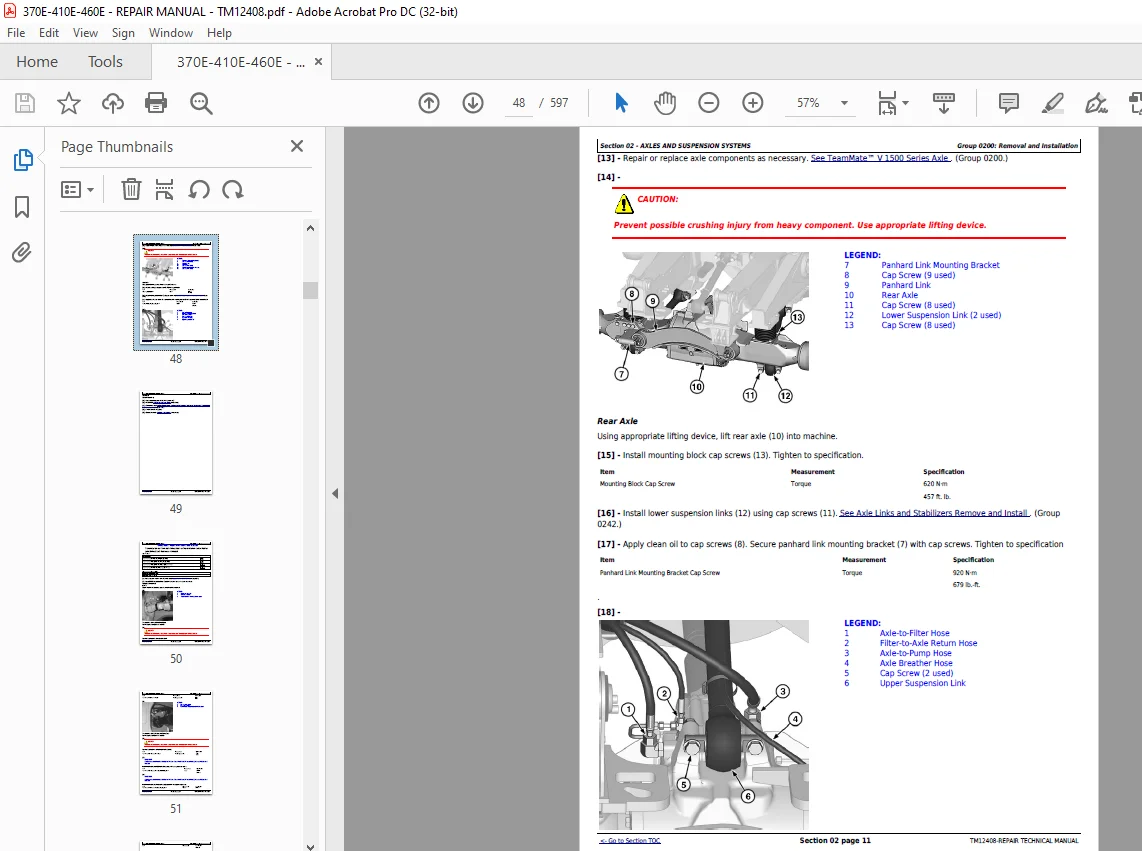
Middle or Rear Axle Remove and Install 45
Group 0225 – Input Drive Shafts and U-Joints 50
Transmission-to-Front Axle Drive Shaft or Transmission-to-Oscillation Joint Drive Shaft Remove and Install 50
Oscillation Joint Drive Shaft Remove and Install 53
Park Brake-to-Middle Axle Drive Shaft Remove and Install 57
Middle Axle-to-Rear Axle Drive Shaft Remove and Install 59
Group 0242 – Axle Mounting Parts 61
Front Suspension Strut Remove and Install 61
Front Suspension Accumulator Remove and Install 62
Axle Links and Stabilizers Remove and Install 63
Axle Link, Stabilizer, and Strut Bushing Replace 65
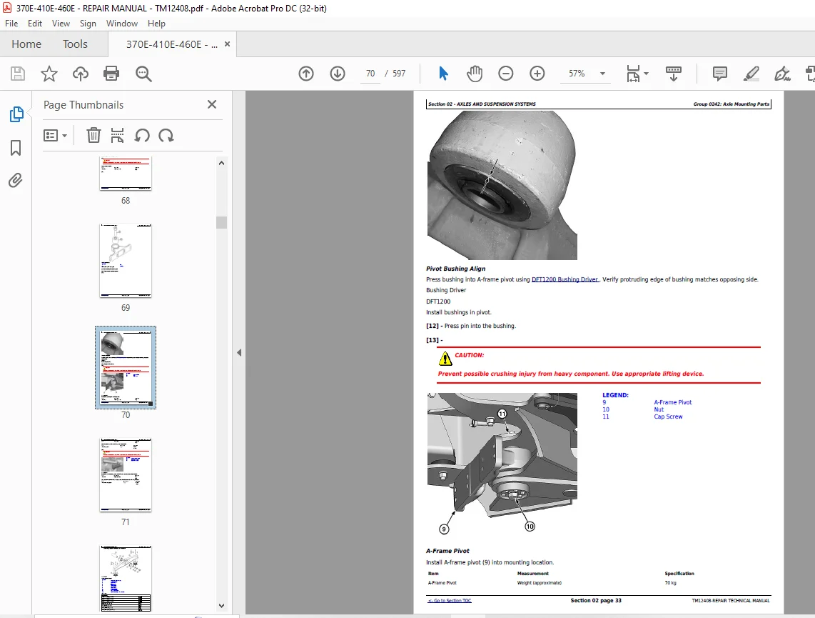
Front Axle Pivot Disassemble and Assemble 67
Walking Beam Remove and Install 72
Walking Beam Bushing Remove and Install 77
Middle and Rear Axle Rubber Mount Remove and Install 79
Strain Gauge Remove and Install 81
Group 0250 – Axle Shaft, Bearings, and Reduction Gears 88
TeamMate V 1500 Series Axle 88
Group 0260 – Hydraulic System 89
Front Axle Pump Remove and Install 89
Rear Axle Pump Remove and Install 89
Front Axle Cooling Manifold Remove and Install 91
Middle Axle Cooling Manifold Remove and Install 93
Rear Axle Cooling Manifold Remove and Install 95
Comfort Ride Control Valve Remove and Install 97
Strut Accumulator Remove and Install 99
Section 03 – TRANSMISSION103
Group 0300 – Removal and Installation103
Transmission Remove and Install103
Transmission Alignment116
Front Transmission Mount Washer Installation120
Group 0325 – Input Drive Shafts and U-Joints122
Engine-to-Transmission Drive Shaft Remove and Install122
Group 0350 – Gear, Shafts, and Power Shift Clutches124
Transmission Disassemble124
Transmission Assemble140
Transmission Clutch (F) Hi/Lo Planetary Disassemble and Assemble157
Transmission Clutch (E) Disassemble and Assemble176
Transmission Clutch (R) Disassemble and Assemble195
Transmission Clutch (B) Disassemble and Assemble208
Transmission Clutch (V) Disassemble and Assemble223
Transmission Clutch (C) Disassemble and Assemble237
Transmission Clutch (D) Disassemble and Assemble251
Transmission Clutch (A) Disassemble and Assemble265
Transmission Clutch (G) Inter-Axle Differential Lock (IDL) Disassemble and Assemble278
Transmission Speed Sensors Remove and Install295
Transmission Clutch (F) Hi/Lo Planetary Remove and Install298
Group 0360 – Hydraulic System304
Transmission Oil Cooler Thermal Bypass Valve Remove and Install304
Transmission Control Valve Remove and Install305
Torque Converter Remove and Install306
Clutch Control Valve Remove and Install306
Retarder Control Valve Remove and Install306
Oil Pump Remove and Install306
Transmission Retarder Remove and Install307
Transmission Control Valve Disassemble and Assemble323
Clutch Control Valve Disassemble and Assemble327
Retarder Control Valve Disassemble and Assemble332
Oil Pump Disassemble and Assemble336
Transmission Retarder Disassemble and Assemble338
Section 04 – ENGINE347
Group 0400 – Removal and Installation347
John Deere Engine347
Engine Remove348
Engine Install354
Engine Crankshaft Damper Remove and Install359
Serpentine Belt Remove and Install360
Section 05 – ENGINE AUXILIARY SYSTEM363
Group 0505 – Cold Weather Starting Aids363
Cold Start Aid—Starting Fluid Nozzle Remove and Install—If Equipped363
Cold Start Aid—Starting Fluid Solenoid Remove and Install—If Equipped365
Cold Start Aid—Block Heater Remove and Install—If Equipped366
Group 0510 – Cooling Systems368
Charge Air Cooler Remove and Install368
Left Radiator Remove and Install370
Right Radiator Remove and Install372
Hydraulic Oil Cooler Remove and Install374
Transmission Oil Cooler Remove and Install376
Fuel Cooler Remove and Install377
Front Axle Oil Cooler Remove and Install379
Middle Axle Oil Cooler Remove and Install381
Group 0520 – Intake System383
Air Cleaner Remove and Install383
Group 0530 – External Exhaust Systems384
Exhaust Tube Remove and Install384
Dump Body Heater Pipe Remove and Install385
Dump Body Heater Exhaust Collar Adjust387
Dump Body Heat Diverter Actuator Remove and Install388
Exhaust Bellows Alignment Procedure392
Diesel Particulate Filter (DPF) Remove and Install397
Exhaust Filter Remove and Install401
Service Filter Cleaning406
Group 0560 – External Fuel Supply Systems407
Fuel Tank Remove and Install407
Fuel Transfer Pump Remove and Install412
Fast Fill Fuel System Disassemble and Assemble—If Equipped414
Section 07 – DAMPER DRIVE417
Group 0752 – Elements417
Output Damper Remove and Install417
Section 09 – STEERING SYSTEM419
Group 0930 – Secondary Steering419
Secondary Steering Pump Remove and Install419
Group 0960 – Hydraulic System422
Steering Valve Remove and Install422
Steering Cylinder Remove and Install426
Steering Bushing Replacement428
Section 10 – SERVICE BRAKES430
Group 1011 – Active Elements430
Service Brake Assembly Remove and Install430
Group 1060 – Hydraulic System431
Bleed Service Brake431
Brake Accumulator Remove and Install432
Brake Valve Remove and Install434
Electronic Brake Valve Remove and Install435
Section 11 – PARK BRAKE438
Group 1111 – Active Elements438
Park Brake Pads Remove and Install438
Park Brake Caliper Remove and Install439
Park Brake Disk Remove and Install442
Park Brake Chamber Remove and Install444
Group 1160 – Hydraulic System446
Park Brake Control Valve Remove and Install446
Section 17 – FRAME OR SUPPORTING STRUCTURE449
Group 1740 – Frame Installation449
Welding on Machine449
Front and Rear Frames Separate450
Articulation Frame Remove and Install457
Articulation Frame Bearings Disassemble and Assemble460
Articulation Frame Bearings Adjust462
Oscillation Joint Disassemble and Assemble465
Oscillation Joint Bearing Cap Screw Installation467
Section 18 – OPERATOR′S STATION470
Group 1810 – Operator Enclosure470
Cab Remove and Install470
Cab Mount Remove and Install479
Cab Tilt Pump and Cylinder Remove and Install481
Cab Tilt Pump and Cylinder Disassemble and Assemble485
Windowpanes Remove and Install487
Cab Door Window Installation490
Group 1821 – Seat and Seat Belt493
Operator’s Seat Remove and Install493
Seat Belt Remove and Install494
Group 1830 – Heating and Air Conditioning496
R134a Refrigerant Cautions and Proper Handling496
R134a Refrigerant Oil Information497
R134a Refrigerant Recovery/Recycling and Charging Station Installation Procedure500
R134a Refrigerant Recover501
Air Conditioning System Flush and Purge502
R134a System Evacuate503
R134a System Charge504
Compressor Remove and Install506
Condenser Remove and Install507
High/Low Pressure Switch Remove and Install508
Receiver-Dryer Remove and Install509
Expansion Valve Remove and Install510
Heater Core and Evaporator Core Remove and Install512
Freeze Control Switch Remove and Install515
Heater Control Valve Remove and Install515
Heater Control Valve Leak Check516
Blower Motor Assembly Remove and Install517
Mode Door Remove and Install518
Section 19 – SHEET METAL AND STYLING521
Group 1910 – Hood or Engine Enclosure521
Hood Remove and Install521
Hood Adjust523
Engine Service Door Remove and Install526
Left Fan Grille Remove and Install528
Right Fan Grille Remove and Install530
Group 1927 – Fenders532
Fender Remove and Install532
Section 21 – MAIN HYDRAULIC SYSTEM535
Group 2160 – Hydraulic System535
Main Hydraulic Pump Remove and Install535
Hydraulic Reservoir Remove and Install538
Dump Body Heat Cylinder Remove and Install546
Dump Body Heat Diverter Valve Remove and Install548
Hydraulic System Manifold Remove and Install550
Hydraulic System Manifold Disassemble and Assemble552
Hydraulic Fan Motor Right Side Remove and Install554
Hydraulic Fan Motor Left Side Remove and Install557
Reversing Hydraulic Fan Motor Left Side Remove and Install (if equipped)560
Reversing Hydraulic Fan Motor Right Side Remove and Install (if equipped)563
Left Hydraulic Fan Pump Remove and Install566
Right Hydraulic Fan Pump Remove and Install567
Hydraulic Attenuator Remove and Install569
General Oil Cleanup Procedure570
Hydraulic Component Failure Cleanup Procedure573
Section 35 – HAULAGE DEVICE576
Group 3540 – Frames576
Dump Body Remove and Install576
Dump Body Align579
Group 3560 – Hydraulic System581
Dump Body Lift Cylinder Remove and Install581
Dump Body Lift Cylinder Disassemble and Assemble583
Dump Body Lift Cylinder Head End Pivot Pin Bushing Remove and Install585
Dump Body Lift Cylinder Rod End Pivot Pin Bushing Remove and Install586
Section 99 – DEALER FABRICATED TOOLS589
Group 9900 – Dealer Fabricated Tools589
DFT1344 Supports590
DFT1187 Bearing Driver592
DFT1196 Bushing Driver593
DFT1199 Bushing Pusher595
DFT1200 Bushing Driver596
DFT1353 Strain Gauge Alignment Tool597
S.M 8/1/25