John Deere Diesel Engine Powertech 4.5L 6.8L Technical Manual CTM207 PDF
$28.95
John Deere Diesel Engine Powertech 4.5L 6.8L Technical Manual CTM207 – PDF DOWNLOAD
Description
John Deere Diesel Engine Powertech 4.5L 6.8L Technical Manual CTM207 – PDF DOWNLOAD
FILE DETAILS:
John Deere Diesel Engine Powertech 4.5L 6.8L Technical Manual CTM207 – PDF DOWNLOAD
Language : English
Pages :256
Downloadable : Yes
File Type : PDF
IMAGES PREVIEW OF THE MANUAL:
DESCRIPTION:
John Deere Diesel Engine Powertech 4.5L 6.8L Technical Manual CTM207 – PDF DOWNLOAD
Foreword
- This manual is written for an experienced technician. Essential tools required in performing certain service work are identified in this manual and are recommended for use. This manual (CTM207) covers only mechanical fuel systems. It is one of eight volumes on 4.5 L and 6.8 L engines. The following companion manual covers the base engine: • CTM104—Base Engine Live with safety: Read the safety messages in the introduction of this manual and the cautions presented throughout the text of the manual.
- This is the safetyalert symbol. When you see this symbol on the machine or in this manual, be alert to the potential for personal injury. Use this component technical manual in conjunction with the machine technical manual. An application listing in Section 01, Group 001 identifies productmodel/ component typemodel relationship. See the machine technical manual for information on component removal and installation, and gaining access to the components. Information is organized in sections and groups for the various components requiring service instruction.
- Section 05 summarizes all applicable essential tools, service equipment and tools, other materials needed to do the job, and service parts kits. Section 06 summarizes all specifications, wear tolerances, and torque values. Before beginning repair on an engine, clean the engine and mount on a repair stand. This manual contains SI Metric units of measure followed immediately by the U.S. customary units of measure. Most hardware on these engines is metric sized. Some components of this engine may be serviced without removing the engine from the machine.
- Refer to the specific machine technical manual for information on components that can be serviced without removing the engine from the machine and for engine removal and installation procedures. Read each block of material completely before performing service to check for differences in procedures or specifications. Follow only the procedures that apply to the engine model number you are working on. If only one procedure is given, that procedure applies to all the engines in the manual. CALIFORNIA PROPOSITION 65 WARNING Diesel engine exhaust and some of its constituents are known to the State of California to cause cancer, birth defects and other reproductive harm.
TABLE OF CONTENTS:
John Deere Diesel Engine Powertech 4.5L 6.8L Technical Manual CTM207 – PDF DOWNLOAD
Contents 7
General Information 9
Safety 11
Work In Ventilated Area 11
Recognize Safety Information 11
Work in Clean Area 11
Dispose of Waste Properly 12
Avoid Harmful Asbestos Dust 12
Handle Fuel Safely—Avoid Fires 12
Prepare for Emergencies 13
Handle Starting Fluid Safely 13
Handle Fluids Safely—Avoid Fires 13
Avoid High-Pressure Fluids 14
Use Proper Lifting Equipment 14
Illuminate Work Area Safely 14
Live With Safety 15
Service Machines Safely 15
Handle Chemical Products Safely 15
Protect Against Noise 16
Remove Paint Before Welding or Heating 16
Stay Clear of Rotating Drivelines 16
Service Cooling System Safely 17
Follow Safety Instructions 17
Use Proper Tools 17
Construct Dealer-Made Tools Safely 18
Practice Safe Maintenance 18
Understand Signal Words 19
Replace Safety Signs 19
Prevent Battery Explosions 19
Protect Against High Pressure Spray 20
Avoid Heating Near Pressurized Fluid Lines 20
Wear Protective Clothing 20
Handle Agricultural Chemicals Safely 21
Handling Batteries Safely 22
Install Fan Guards 23
Avoid Hot Parts 23
Engine Identification and Applications 25
Engine Serial Number Plate Information 25
OEM Engine Option Code Label 27
Information Relative to Emissions Regulations 27
Engine Application Charts 28
Fuels, Lubricants, and Coolants 37
Diesel Fuel 37
Biodiesel Fuel 38
Minimizing the Effect of Cold Weather on Diesel Engines 39
Handling and Storing Diesel Fuel 40
Lubricity of Diesel Fuel 40
Testing Diesel Fuel 40
Repair and Adjustments 42
Mechanical Fuel System Repair and Adjustments 43
Fuel System—General Information 43
Relieve Fuel System Pressure 43
Remove and Install Final Fuel Filter and/or Primary Fuel Filter/ 44
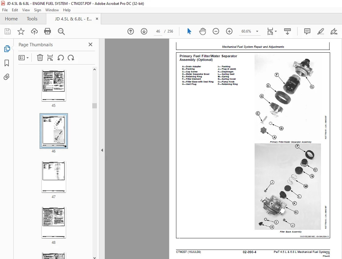
Primary Fuel Filter/Water Separator Assembly (Optional) 46
Final Fuel Filter Assembly 47
Replace Final Fuel Filter and Primary Fuel Filter/Water Separato 48
Remove Lucas and Stanadyne Fuel Supply Pump 49
Bench Test Lucas and Stanadyne Fuel Supply Pump 50
Install Lucas and Stanadyne Fuel Supply Pump 51
Remove Denso In-Line Fuel Supply Pump 52
Test Denso In-Line Fuel Supply Pump for Leaks 52
Disassemble Denso In-Line Fuel Supply Pump 53
Inspect and Repair Denso In-Line Fuel Supply Pump Components 55
Assemble Denso In-Line Fuel Supply Pump 57
Install Denso In-Line Fuel Supply Pump 57
Remove Motorpal Fuel Supply Pump 58
Inspect Motorpal Fuel Supply Pump 58
Install Motorpal Fuel Supply Pump 58
Service Denso Injection Pump Overflow Valve 59
Remove and Install Denso Fuel Shut-Off Solenoid 60
Remove and Install Delphi/Lucas Fuel Shut-Off Solenoid 60
Remove and Install Motorpal Fuel Shut-Off Solenoid—If Equipped 61
Remove and Install Stanadyne Cold Start Advance Solenoid and Val 61
Remove and Install Delphi/Lucas Cold Start Advance Switch and Ha 63
Delphi/Lucas and Stanadyne Rotary Fuel Injection Pump Timing 64
Denso and Motorpal In-Line Injection Pump Static Timing 65
Stanadyne Rotary Fuel Injection Pump Identification 67
Remove Stanadyne Model DB2 and DB4 Injection Pump (without Lock 68
Remove Stanadyne Model DB4 Injection Pump (with Lock Shaft Timin 69
Inspect Stanadyne Injection Pump Drive Gear ID and Shaft OD 72
Repair Stanadyne Fuel Injection Pump 72
Install Stanadyne Model DB2 and DB4 Injection Pump (without Lock 73
Install Stanadyne Model DB4 Injection Pump (with Lock Shaft Timi 75
Remove Delphi/Lucas Fuel Injection Pump 79
Repair Delphi/Lucas Fuel Injection Pump 81
Install Delphi/Lucas Fuel Injection Pump 81
Remove Denso Fuel Injection Pump 83
Repair Denso Fuel Injection Pump 85
Install Denso Fuel Injection Pump 86
Replace Motorpal Fuel Injection Pump Delivery Valve O-Rings 89
Remove Motorpal Fuel Injection Pump 89
Repair Motorpal Fuel Injection Pump 92
Install Motorpal Fuel Injection Pump 92
Repair Aneroid 95
Transfer Fuel Injection Pump Timing Mark onto Replacement Front 96
Fuel Injection Nozzle Identification 97
Diagnose Fuel Injection Nozzle Malfunctions 98
Remove Fuel Injection Nozzles (95 mm) 99
Clean Fuel Injection Nozzle Bore (95 mm)100
Clean Fuel Injection Nozzles (95 mm)100
Test Fuel Injection Nozzles (95 mm)101
Disassemble Fuel Injection Nozzles (95 mm)103
Inspect and Clean Fuel Injection Nozzle Body (95 mm)105
Inspect and Clean Valve and Valve Seat (95 mm)106
Inspect Valve Adjusting Mechanism (95 mm)107
Assemble Fuel Injection Nozzles (95 mm)108
Adjust Fuel Injection Nozzles (95 mm)108
Install Seals on Fuel Injection Nozzle(95 mm)112
Install Fuel Injection Nozzles (95 mm)113
Remove Fuel Injection Nozzles (VCO 17 mm)114
Clean Fuel Injection Nozzle Bore(VCO 17 mm)115
Clean Fuel Injection Nozzles (VCO 17 mm)115
Test Fuel Injection Nozzles (VCO 17 mm)116
Install Seals on Fuel Injection Nozzle(VCO 17 mm)118
Install Fuel Injection Nozzles (VCO 17 mm)119
Bleed the Fuel System120
Theory of Operation123
Mechanical Fuel Systems Operation125
Fuel Injection Pump—General Information125
Fuel System Operation—Rotary Fuel Injection Pump126
Fuel System Operation—In-Line Fuel Injection Pump128
Fuel Supply Pump Operation—Rotary Injection Pump129
Fuel Supply Pump Operation—In-Line Injection Pump129
Cold Start Advance System Operation (Rotary Pumps)132
Light Load Advance Operation (Rotary Pumps)132
Final Fuel Filter/Water Separator Operation133
Stanadyne Rotary Fuel Injection Pump Operation134
Delphi/Lucas Rotary Fuel Injection Pump Operation136
Denso and Motorpal In-Line Fuel Injection Pump Operation137
Aneroid Operation (If Equipped)138
Fuel Injection Nozzles Operation (95 mm)139
Fuel Injection Nozzles Operation (VCO 17 mm)140
Diagnostics144
Observable Diagnostics and Tests145
About This Section of the Manual145
E1—Engine Cranks/Won’t Start146
E1—Engine Cranks/Won’t Start Diagnostic Procedure146
E2—Engine Misfires/Runs Irregularly149
E2—Engine Misfires/Runs Irregularly Diagnostic Procedure149
E3—Engine Does Not Develop Full Power152
E3—Engine Does Not Develop Full Power Diagnostic Procedure152
E4—Engine Emits Excessive White Exhaust Smoke155
E4—Engine Emits Excessive White Exhaust Smoke Diagnostic Procedu155
E5—Engine Emits Excessive Black or Gray Exhaust Smoke156
E5—Engine Emits Excessive Black or Gray Exhaust Smoke Diagnostic157
E6—Engine Will Not Crank159
E7—Engine Idles Poorly159
E8—Abnormal Engine Noise160
F1—Fuel Supply System Check162
F1—Fuel Supply System Check162
F2—Excessive Fuel Consumption165
F3—Fuel in Oil165
Cylinder Misfire Test (Engine Running)165
Using TACH-N-TIME as Tachometer166
Using TIME TRACTIME TRAC is a registered trademark of Stanadyne 166
Check and Adjust Rotary Injection Pump Dynamic Timing Using TACH167
Check and Adjust Rotary Injection Pump Dynamic Timing Using TIME172
Check and Adjust In-Line Injection Pump Static Timing177
Check Fuel Supply Quality178
Test Air in Fuel179
Check for Restricted Fuel Return Line180
Measure Fuel Supply Pump Pressure—Rotary Injection Pump181
Measure Fuel Supply Pump Pressure—In-Line Injection Pump181
Test Fuel Supply Pump for Leaks—In-Line Injection Pump182
Check Fuel Supply Pump Operation—In-Line Injection Pump183
Service Denso Fuel Supply Pump184
Check Cold Start Switch Operation—Rotary Pumps184
Check Cold Start Advance System Operation—Rotary Pumps185
Check Light Load Advance Operation—Rotary Pumps186
Check Fuel Shut-Off Solenoid Operation—In-Line Injection Pumps186
Test Fuel Shut-Off Solenoid Resistance—Delphi/Lucas Pump187
Test Fuel Shut-Off Solenoid Resistance—Denso Pump187
Test Fuel Shut-Off Solenoid Resistance—Motorpal Pump187
Adjust Fuel Shut-Off Solenoid Linkage—In-Line Injection Pumps188
Check and Adjust Engine Speeds on Delphi/Lucas Pump189
Adjust Variable Speed on Generator Set Engines (Delphi/Lucas Pum189
Check and Adjust Engine Speeds on Stanadyne Pump190
Adjust Variable Speed (Droop) on Generator Set Engines (3—5% Gov191
Check and Adjust Fast Idle Speed—Denso and Motorpal Fuel Injecti192
Check and Adjust Slow Idle Speed—Denso Fuel Injection Pump193
Check and Adjust Slow Idle Speed—Motorpal Fuel Injection Pump194
Change Engine Rated Speed and Adjust Droop—Denso Fuel Injection 195
Test Fuel Injection Nozzles (Engine Running)196
Fuel Drain-Back Test Procedure197
Bleed the Fuel System197
Tools and Other Materials201
Repair Tools and Other Materials203
Mechanical Fuel System Essential Tools203
Mechanical Fuel System Other Material207
Mechanical Fuel System Service Equipment and Tools207
Diagnostic Service Tools and Other Materials209
Mechanical Fuel System Diagnostic Essential Tools209
Mechanical Fuel System Diagnostic Service Equipment and Tools212
Dealer Fabricated Service Tools213
How to Make Tools213
DFRG5—Injection Pump Front Plate Timing Mark Transfer Tool213
Specifications215
Repair and General OEM Specifications217
Unified Inch Bolt and Screw Torque Values217
Metric Bolt and Screw Torque Values218
General OEM Engine Specifications219
Mechanical Fuel System Repair Specifications221
Diagnostic Specifications227
Fuel Injection Pump Specifications227
Fuel Injection Pump Specifications (Agricultural Applications)228
Fuel Injection Pump Specifications (Commercial and Consumer Equi235
Fuel Injection Pump Specifications (Construction and Forestry Eq237
Fuel Injection Pump Specifications (OEM Applications)243
Page Number 7
Section 01 9
Group 000 11
Group 001 25
Group 002 37
Section 02 42
Group 090 43
Section 03123
Group 130125
Section 04144
Group 150145
Section 05201
Group 170203
Group 180209
Group 190213
Section 06215
Group 200217
Group 210227
S.M 8/1/25