John Deere Diesel Engine Powertech 10.5 L 12.5 L Technical Manual CTM188 PDF
$31.95
John Deere Diesel Engine Powertech 10.5 L 12.5 L Technical Manual CTM188 – PDF DOWNLOAD
Description
John Deere Diesel Engine Powertech 10.5 L 12.5 L Technical Manual CTM188 – PDF DOWNLOAD
FILE DETAILS:
John Deere Diesel Engine Powertech 10.5 L 12.5 L Technical Manual CTM188 – PDF DOWNLOAD
Language : English
Pages :646
Downloadable : Yes
File Type : PDF
IMAGES PREVIEW OF THE MANUAL:
DESCRIPTION:
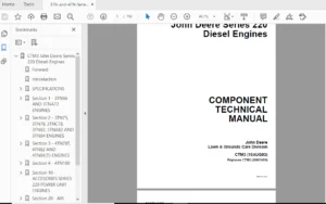
John Deere Diesel Engine Powertech 10.5 L 12.5 L Technical Manual CTM188 – PDF DOWNLOAD
Foreword
- This manual is written for an experienced technician. Special tools required in performing certain service work are identified in this manual and are recommended for use. This manual (CTM188) covers the dual rail and single rail fuel systems on 10.5 L and 12.5 L engines with John Deere Level 6 electronic fuel control. It is one of three volumes. The following two companion manuals cover the base engine and Lucas electronic fuel systems: · CTM100—10.5 L and 12.5 L Diesel Engines—Base Engine · CTM115—10.5 L and 12.5 L Diesel Engines—Lucas Electronic Fuel Systems With Lucas EUIs This new CTM includes single rail fuel system, dual rail fuel system and electrical engine control repair procedures formerly in CTM100, Groups 35, 36 and 45 (9NOV99).
- A complete set of all three manuals covering 10.5 L and 12.5 L engines can be procured by ordering CTM650 Binder Set. Live with safety: Read the safety messages in the introduction of this manual and the cautions presented throughout the text of the manual. This is the safety-alert symbol. When you see this symbol in this manual, be alert to the potential for personal injury. Use this component technical manual in conjunction with the base engine repair manual (CTM100) and the respective machine technical manual. See the repair manual for information on component removal and installation, and gaining access to the components.
- This manual is divided in three parts: repair, theory of operation and diagnostics. Repair procedures are provided for the fuel system and electrical engine control system. The theory of operation section contains information that explains how these engine subsystems operate. The diagnostics section helps identify the cause of engine problems. Applicable special tools and other materials needed to do the job, specifications, and helpful reference materials are covered in separate groups toward end of manual.
- Engine Training Guide (DSEGET550A) is available to give the service technician a detailed overview of general engine construction and design features. This manual is recommended prior to performing major service procedures on POWERTECHâ 10.5 L and 12.5 L engines. Fundamental service information is available from other sources covering basic theory of operation, fundamentals of troubleshooting, general maintenance, and basic type of failures and their causes. This manual contains SI Metric units of measure followed immediately by the U.S. customary units of measure. Most hardware on these engines is metric sized. CALIFORNIA PROPOSITION 65 WARNING: Diesel engine exhaust and some of its constituents are known to the State of California to cause cancer, birth defects, and other reproductive harm
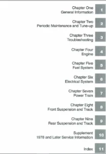
TABLE OF CONTENTS:
John Deere Diesel Engine Powertech 10.5 L 12.5 L Technical Manual CTM188 – PDF DOWNLOAD
Contents 5
General Information 7
Safety 9
Handle Fluids Safely—Avoid Fires 9
Handle Starting Fluid Safely 9
Service Cooling System Safely 9
Prevent Battery Explosions 10
Prepare for Emergencies 10
Handling Batteries Safely 11
Avoid High-Pressure Fluids 12
Wear Protective Clothing 12
Service Machines Safely 13
Work In Ventilated Area 13
Work in Clean Area 13
Remove Paint Before Welding or Heating 14
Avoid Heating Near Pressurized Fluid Lines 14
Illuminate Work Area Safely 15
Practice Safe Maintenance 15
Use Proper Tools 16
Dispose of Waste Properly 16
Live With Safety 17
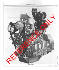
Engine Identification 19
Engine Model Designation 19
Engine Serial Number Plate Information 20
Engine Option Code Label 21
Engine Application Chart 22
Distinguishing ECUs 23
Fuels 25
Lubricants and Coolant 25
Diesel Fuel – Tier 1 25
Diesel Fuel – Tier 2 26
Bio-Diesel Fuel 28
Lubricity of Diesel Fuel 29
Dieselscan Fuel Analysis 29
Repair and Adjustments 31
Dual Rail Fuel System Repair and Adjustment 33
Dual Rail Fuel System Components (Earlier Engines) 33
Replace Final (Secondary) Fuel Filter Element 35
Replacing Primary Fuel Filter/Water Separator 36
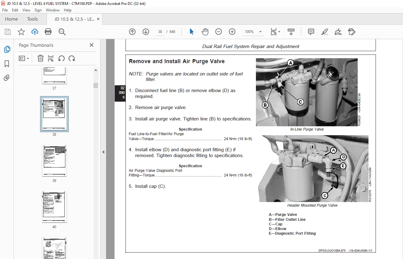
Remove and Install Air Purge Valve 38
Remove and Install Primary Fuel Filter Check Valve 39
Remove and Install Fuel System Surge Tank (6125ADW01/70 Engines) 40
Remove and Install Dual Rail Fuel Supply Pump 41
Remove and Install Dual Rail Fuel Manifold 43
Inspect Fuel Pressure Regulating Valve and Return Check Valve 45
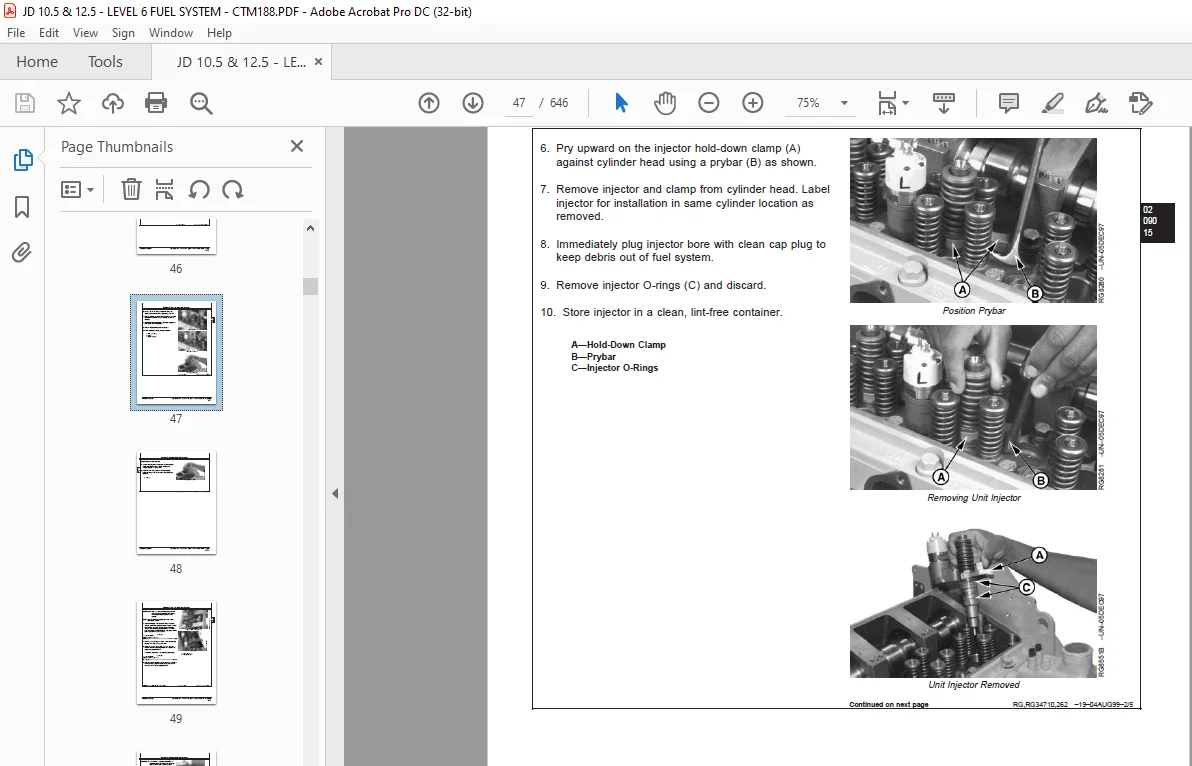
Remove and Install Electronic Unit Injectors 46
Adjust Electronic Unit Injector Preload 51
Replace Electronic Unit Injector O-Rings 53
Replace Electronic Unit Injector Thrust Sleeve, Pad and O-Ring 53
Flush Fuel Rails 54
Bleed Fuel System 55
Single Rail Fuel System Repair and Adjustment 57
General Information 57
Single Rail Fuel System Components (Later Engines) 58
Fuel Filter/Water Separator Assembly 59
Replacing Fuel Filter/Water Separator 60
Remove and Install Low Pressure Regulating Valve 64
Remove and Install High Pressure Regulating Valve 65
Remove and Install 100 Micron Internal Filter Housing Screen Insert 67
Remove and Install Fuel Filter Check Valve 68
Remove and Install Primer Pump 68
Remove and Install Single Rail Fuel Supply Pump 69
Remove and Install Electronic Unit Injectors (Single Rail Fuel System) 71
Adjust Electronic Unit Injector Preload 76
Replace Electronic Unit Injector O-Rings 78
Replace Electronic Unit Injector Thrust Sleeve, Pad and O-Ring 78
Bleed Fuel System 79
Electrical Engine Control Repair and Adjustment 81
John Deere Level 6 Electronic Control System 81
Remove and Install Coolant Temperature Sensor 82
Remove and Install Fuel Temperature Sensor (Dual Rail System) 83
Remove and Install Fuel Temperature Sensor (Single Rail System) 83
Remove and Install Fuel Pressure Sensor (Single Rail Fuel System) 84
Remove and Install Water-in-Fuel Sensor (Single Rail Fuel System) 85
Remove and Install Oil Pressure Sensor 86
Remove and Install Manifold Air Temperature (MAT) Sensor 87
Remove and Install Manifold Absolute Pressure (MAP) Sensor 88
Remove and Install Camshaft Position Sensor 89
Remove and Install Crankshaft Position Sensor 90
Connectors 92
Use Electrical Insulating Compound 92
Using High-Pressure Washer 92
Repair WEATHERPACK™ Connector 93
Remove Blade Terminals from Connector Body 96
Repair (Pull Type) METRI-PACK™ Connectors 97
Repair (Push Type) METRI-PACK™ Connectors 99
Repair DEUTSCH™ Connectors102
Repair CINCH Connectors105
Theory of Operation107
Electronic Fuel System Operation109
About This Group109
Low Pressure Dual Rail Fuel Supply System Operation110
Electronic Unit Injector (EUI) Operation on the Dual Rail Fuel System112
Low Pressure Single Rail Fuel Supply System Operation116
Electronic Unit Injector (EUI) Operation on the Single Rail Fuel System118
Electrical Control System Operation123
Electronic Control System Glossary of Terms123
Electronic Control System Overview126
Electronic Control System Operation128
Monitoring Engine Parameters128
Measuring Temperature129
Measuring Pressure131
Water In Fuel Sensor132
Measuring Throttle Position132
Determining Engine Speed and Piston Position137
Engine Control Unit (ECU)142
Controller Area Network (CAN)144
Cruise Control Operation144
Engine Protection145
Different Derate Programs145
Multiple Torque Curve Selection146
Governor Droop Mode Selection147
Engine Control Unit (ECU) Self-Diagnosis148
Diagnostics151
Observable Diagnostics and Tests157
About this Group of the Manual157
E1 – Engine Cranks/Won’t Start158
E1 – Engine Cranks/Won’t Start Diagnostic Procedure158
Check Dual Rail Fuel Supply Pressure203
Bleed Dual Rail Fuel System204
Check Single Rail Fuel Supply Pressure205
Bleed Single Rail Fuel System206
Restarting Engine That Has Run Out Of Fuel (Single Rail Fuel System)207
Trouble Code Diagnostics and Tests209
About This Group of the Manual209
Electrical Concepts209
Electrical Circuit Malfunctions210
Troubleshooting Circuit Malfunctions213
Using a Digital Multimeter217
Engine Configuration Data Parameters on Diagnostic Gauge218
Viewing Active DTCs on Diagnostic Gauge220
Viewing Stored DTCs on Diagnostic Gauge220
Clearing Stored DTCs on Diagnostic Gauge221
Connecting to Diagnostic Scan Tool (DST) or SERVICE ADVISOR™222
Data Parameter Description224
Engine Test Instructions—Cylinder Misfire Test227
Engine Test Instructions—Compression Test228
Engine Test Instructions— Cylinder Cutout Test229
Cylinder Cutout Test Using JDG1250230
Reprogramming Engine Control Unit (ECU)232
Downloading Payload File For DST233
Reprogramming Engine Control Unit (ECU) With DST238
Downloading Payload File For SERVICE ADVISOR™243
Reprogramming Engine Control Unit (ECU) With SERVICE ADVISOR™251
Diagnostic Trouble Codes (DTCs)255
Listing of Diagnostic Trouble Codes (DTCs) on ECU256
Diagnostic Procedure260
Intermittent Fault Diagnostics261
T1 – Multi-state Throttle Input High262
00097031 — Auxiliary Engine Shutdown Switch Active552
00097131 — External Fuel Derate Switch Active553
00110931 — Engine Shutdown Warning554
00111031 — Engine Shutdown555
00156931 — Fuel Derate556
00200013 — Security Violation557
Tools559
Repair Tools561
Fuel System Essential Tools561
Fuel System Service Equipment and Tools562
Fuel System Other Material563
Electronic Control System Essential Tools564
Electronic Control System Service Equipment and Tools570
Electronic Control System Other Material570
Diagnostic Service Tools571
Engine Diagnostics and Testing Procedure Tools571
Electronic Control System Diagnostic Tools572
Specifications575
Repair Specifications577
Unified Inch Bolt and Cap Screw Torque Values577
Metric Bolt and Cap Screw Torque Values578
General OEM Engine Specifications579
Dual Rail Fuel System Specifications580
Single Rail Fuel System Specifications582
Electronic Engine Control System Specifications584
Diagnostic Specifications585
Fuel System Diagnostic Specifications585
Application Specifications586
Combines – Sensor Specifications588
Combines – Torque Curve Selection590
Combines – Governor Mode Selection590
Combines – ECU Terminal Identification591
Excavators – Sensor Specifications592
Excavators – Torque Curve Selection594
Excavators – Governor Mode Selection595
Excavators – ECU Terminal Identification596
Forage Harvesters – Sensor Specifications598
Forage Harvesters – Torque Curve Selection600
Forage Harvesters – Governor Mode Selection601
Forage Harvesters – ECU Terminal Identification602
Loaders – Sensor Specifications604
Loaders – Torque Curve Selection606
Loaders – Governor Mode Selection607
Loaders – ECU Terminal Identification608
Marine Engines – Sensor Specifications610
Marine Engines – Torque Curve Selection612
Marine Engines – Governor Mode Selection613
Marine Engines – ECU Terminal Identification614
Marine Engines – Electronic Control System Wiring Diagram616
125 L Marine Application Wheel House Panel Electrical Wiring Diagram617
125 L Marine Application Fly Bridge Panel Electrical Wiring Diagram618
OEM Engines – Sensor Specifications620
OEM Engines – Torque Curve Selection623
OEM Engines – Governor Mode Selection625
OEM Engines – ECU Terminal Identification626
OEM Engines – Electronic Control System Wiring Diagram628
OEM Engines – 105L & 125L Instrument Panel/Engine Start Components Electrical Wiring Diagram630
OEM Engines – 105L & 125L Instrument Panel/Engine Start Components Electrical Wiring Diagram – Continued631
Tractors – Sensor Specifications632
Tractors – Torque Curve Selection634
Tractors – Governor Mode Selection636
Tractors – ECU Terminal Identification637
Page Numbers 5
Section 01 7
Group 000 9
S.M 8/1/25