Trusted Business
Verified & Licensed
Virus Free Files
100% Safe Downloads
Secure Payment
SSL Protected
Instant Delivery
Available Immediately
John Deere 9.0 L OEM Diesel Engines Final Tier 4 Stage IV Platform Component Technical Manual CTM117719 – PDF DOWNLOAD
$40.95
John Deere 9.0 L OEM Diesel Engines Final Tier 4 Stage IV Platform Component Technical Manual CTM117719 – PDF DOWNLOAD
Instant PDF Download
Available immediately
Save to Your Device
Download & keep forever
Antivirus Scanned
100% virus-free
Trusted Worldwide
175,000+ customers
Description
John Deere 9.0 L OEM Diesel Engines Final Tier 4 Stage IV Platform Component Technical Manual CTM117719 – PDF DOWNLOAD
FILE DETAILS:
John Deere 9.0 L OEM Diesel Engines Final Tier 4 Stage IV Platform Component Technical Manual CTM117719 – PDF DOWNLOAD
Language : English
Pages : 2524
Downloadable : Yes
File Type : PDF
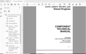
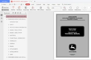
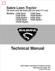
IMAGES PREVIEW OF THE MANUAL:
DESCRIPTION:
John Deere 9.0 L OEM Diesel Engines Final Tier 4 Stage IV Platform Component Technical Manual CTM117719 – PDF DOWNLOAD
Foreword
- This repair manual is valid for the engines.
- This manual is written for an experienced technician. Essential tools required in performing certain service work are identified in this manual.
- Live with safety: Read the safety messages in the introduction of this manual and the cautions presented throughout the text of the manual.
- Information in this manual is organized in sections and sub divided into groups.
- Section 01 covers the safety measures to follow while repairing the engine; engine identification features, engine emission & application details, and information about the fuels, lubricants & coolants.
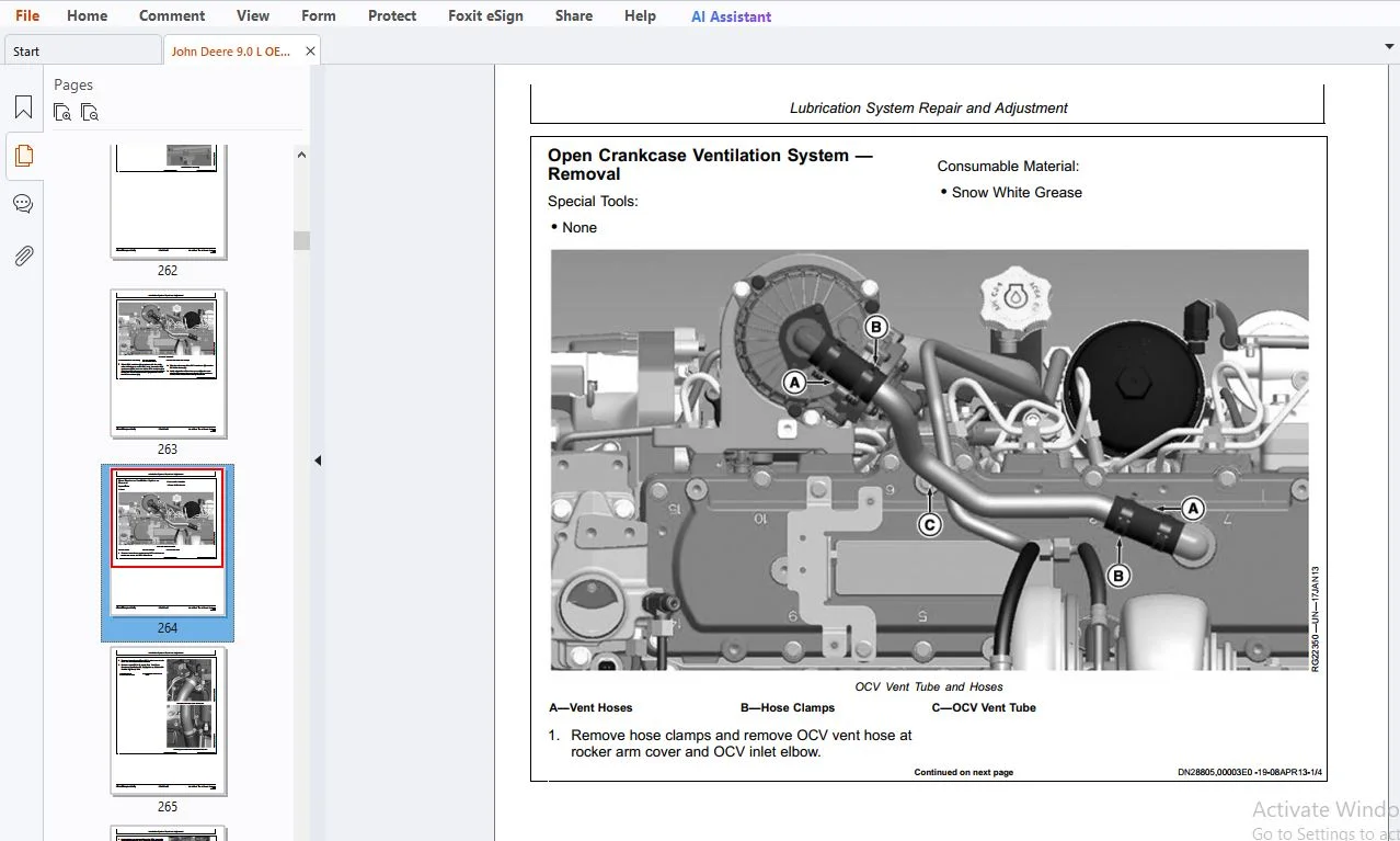
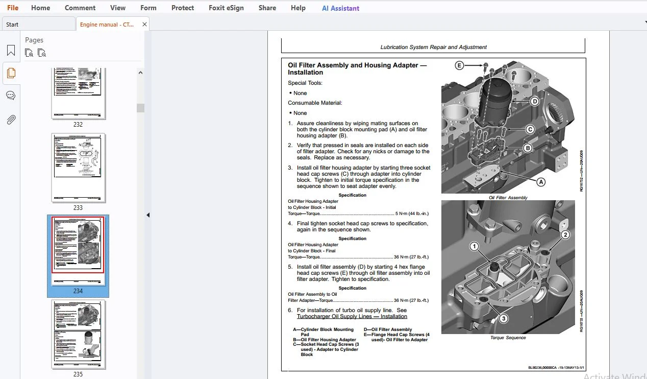
- Section 02 covers the Repair and Adjustment procedures.
- Section 03 explains Systems Theory of Operation.
- Section 04 is the diagnostics section that provides troubleshooting procedures to find problems.
- Section 05 lists all applicable service equipment and tools, other materials needed to do the job.
- Section 06 details all specifications, wear tolerances, torque values and contains the wiring diagrams.
- This manual contains SI Metric units of measure followed immediately by the U.S. customary units of measure.
- Most hardware on these engines is metric sized. Read each block of material completely before performing service to check for differences in procedures or specifications. Follow only the procedures that apply to the component you are working on. Component Technical Manuals are concise service guides for specific components. Component technical manuals are written as stand-alone manuals covering multiple machine applications.
- Fundamental service information is available from other sources covering basic theory of operation, fundamentals of troubleshooting, general maintenance, and basic type of failures and their causes.
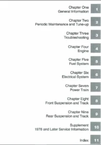
TABLE OF CONTENTS:
John Deere 9.0 L OEM Diesel Engines Final Tier 4 Stage IV Platform Component Technical Manual CTM117719 – PDF DOWNLOAD
Contents........................................................................................................................... 11 General Information............................................................................................................ 13 Safety..................................................................................................................... 15 Understand Signal Words................................................................................................ 15 Recognize Safety Information........................................................................................... 15 Replace Safety Signs................................................................................................... 15 Follow Safety Instructions............................................................................................. 16 California Proposition 65 Warning...................................................................................... 16 Exhaust Filter Cleaning................................................................................................ 16 Avoid Hot Exhaust...................................................................................................... 16 Work In Ventilated Area................................................................................................ 17 Decommissioning — Proper Recycling and Disposal of Fluids and Components............................................... 17 Prevent Machine Runaway................................................................................................ 18 Practice Safe Maintenance.............................................................................................. 18 Work in Clean Area..................................................................................................... 19 Wear Protective Clothing............................................................................................... 19 Service Machines Safely................................................................................................ 19 Use Proper Tools....................................................................................................... 20 Construct Dealer-Made Tools Safely..................................................................................... 20 Support Machine Properly............................................................................................... 20 Use Proper Lifting Equipment........................................................................................... 21 Protect Against Noise.................................................................................................. 21 Illuminate Work Area Safely............................................................................................ 21 Install All Guards..................................................................................................... 22 Stay Clear of Rotating Drivelines...................................................................................... 22 Protect Against High Pressure Spray.................................................................................... 22 Service Cooling System Safely.......................................................................................... 23 Remove Paint Before Welding or Heating................................................................................. 23 Precautions for Welding................................................................................................ 24 Wait Before Opening High-Pressure Fuel System.......................................................................... 24 Avoid High-Pressure Fluids............................................................................................. 25 Avoid Heating Near Pressurized Fluid Lines............................................................................. 25 Avoid Static Electricity Risk When Refueling........................................................................... 26 Handle Fluids Safely—Avoid Fires....................................................................................... 26 Prepare for Emergencies................................................................................................ 26 Handling Batteries Safely.............................................................................................. 27 Prevent Acid Burns..................................................................................................... 28 Prevent Battery Explosions............................................................................................. 28 Live With Safety....................................................................................................... 29 Engine Identification...................................................................................................... 31 Engine Serial Number Plate Information................................................................................. 31 OEM Engine Option Code Label........................................................................................... 32 Information Relative to Emissions Regulations.......................................................................... 32 Emissions Control System Certification Label........................................................................... 33 Fuels, Lubricants, and Coolant............................................................................................. 35 Diesel Exhaust Fluid (DEF) — Use in Selective Catalytic Reduction (SCR) Equipped Engines............................... 35 Storing Diesel Exhaust Fluid (DEF)..................................................................................... 35 Refilling Diesel Exhaust Fluid (DEF) Tank.............................................................................. 36 Testing Diesel Exhaust Fluid (DEF)..................................................................................... 37 Disposal of Diesel Exhaust Fluid (DEF)................................................................................. 37 Diesel Fuel............................................................................................................ 38 Supplemental Diesel Fuel Additives..................................................................................... 38 Lubricity of Diesel Fuel............................................................................................... 39 Handling and Storing Diesel Fuel....................................................................................... 39 BioDiesel Fuel......................................................................................................... 40 Testing Diesel Fuel.................................................................................................... 41 Fuel Filters........................................................................................................... 41 Minimizing the Effect of Cold Weather on Diesel Engines................................................................ 42 John Deere Break-In Plus™ Engine Oil — Interim Tier 4, Final Tier 4, Stage IIIB, and Stage IV.......................... 43 Diesel Engine Oil — Interim Tier 4, Final Tier 4, Stage IIIB, and Stage IV............................................. 43 Engine Oil and Filter Service Intervals — Interim Tier 4, Final Tier 4, Stage IIIB, and Stage IV — OEM Applications.... 44 Diesel Engine Oil and Filter Service Intervals......................................................................... 44 Mixing of Lubricants................................................................................................... 44 Alternative and Synthetic Lubricants................................................................................... 45 Lubricant Storage...................................................................................................... 45 Oil Filters............................................................................................................ 45 Diesel Engine Coolant (engine with wet sleeve cylinder liners)......................................................... 46 Water Quality for Mixing with Coolant Concentrate...................................................................... 47 Operating in Warm Temperature Climates................................................................................. 47 Testing Coolant Freeze Point........................................................................................... 48 Disposing of Coolant................................................................................................... 48 Repair and Adjustments......................................................................................................... 56 Engine Rebuild............................................................................................................. 57 Check Air Intake System................................................................................................ 57 Check and Service Cooling System....................................................................................... 57 Check Crankcase Vent System............................................................................................ 59 Check Electrical System................................................................................................ 59 Check Exhaust System................................................................................................... 60 Clean Engine........................................................................................................... 60 Disconnect Turbo Oil Inlet Line — Rollover Stand....................................................................... 61 Engine Assembly Sequence............................................................................................... 62 Engine Break-In Procedure.............................................................................................. 63 Engine Disassembly Sequence............................................................................................ 65 Engine Repair Stand.................................................................................................... 66 General Tune-Up Recommendations........................................................................................ 66 Install Adapters on Repair Stand....................................................................................... 67 Install Lift Straps — 6090HFC09........................................................................................ 67 Lift Straps — Removal.................................................................................................. 68 Lifting Procedure...................................................................................................... 69 Mount Engine on Repair Stand........................................................................................... 70 Overhaul Guidelines.................................................................................................... 71 Safety Precautions..................................................................................................... 72 Sealant Application Guidelines......................................................................................... 73 Cylinder Head and Valve Repair and Adjustment.............................................................................. 75 Cylinder Block Top Deck — Cleaning and Inspection...................................................................... 75 Cylinder Head — Cleaning and Inspection................................................................................ 75 Cylinder Head — Flatness Check......................................................................................... 76 Cylinder Head — Installation........................................................................................... 77 Cylinder Head — Removal................................................................................................ 80 Cylinder Head — Thickness Measurement.................................................................................. 82 Cylinder Head Gasket — Inspection...................................................................................... 83 Fuel Injector Sleeves — Installation................................................................................... 84 Fuel Injector Sleeves — Removal........................................................................................ 85 Push Rod — Cleaning and Inspection..................................................................................... 87 Rocker Arm Cover — Inspection.......................................................................................... 87 Rocker Arm Cover — Installation........................................................................................ 88 Rocker Arm Cover — Removal............................................................................................. 90 Rocker Arm Shaft Assembly — Assemble................................................................................... 92 Rocker Arm Shaft Assembly — Inspection................................................................................. 94 Rocker Arm Shaft Assembly — Installation............................................................................... 96 Rocker Arm Shaft Assembly — Removal.................................................................................... 97 Rocker Arm Shaft Assembly — Tear Down.................................................................................. 98 Valve — Cleaning and Inspection........................................................................................ 100 Valve — Clearance Adjustment........................................................................................... 101 Valve — Grinding....................................................................................................... 104 Valve — Measurement.................................................................................................... 105 Valve — Recess Measurement............................................................................................. 106 Valve Assembly — Installation.......................................................................................... 106 Valve Assembly — Removal............................................................................................... 108 Valve Bridge, Valve Rotator, and Valve Keepers — Inspection............................................................ 109 Valve Guides — Cleaning and Measurement................................................................................ 109 Valve Guides — Installation............................................................................................ 110 Valve Guides — Removal................................................................................................. 111 Valve Seat — Cleaning and Inspection................................................................................... 111 Valve Seat — Grinding and Measurement.................................................................................. 112 Valve Seat — Installation.............................................................................................. 113 Valve Seat — Removal................................................................................................... 113 Valve Springs — Inspection and Measurement............................................................................. 114 Cylinder Block, Liners, Pistons, and Rods Repair and Adjustment............................................................ 115 Connecting Rod — Center-to-Center Bore Measurement..................................................................... 115 Connecting Rod — General Information................................................................................... 116 Connecting Rod and Cap — Inspection.................................................................................... 117 Connecting Rod Bearing — Inspection and Measurement.................................................................... 118 Connecting Rod Bearing — Inspection and Measurement (Rod and Crankshaft in Engine)..................................... 119 Connecting Rod Cap Screw — Torque Procedure............................................................................ 120 Connecting Rod Pin Bore — Cleaning and Inspection...................................................................... 121 Cylinder Block Oil, Coolant, and Camshaft Frost Plugs — Installation................................................... 122 Cylinder Block — Inspect and Reclaim................................................................................... 124 Cylinder Block — Measurements.......................................................................................... 134 Cylinder Block, Piston, and Rod — Troubleshooting Guide................................................................ 135 Cylinder Liner — Cleaning.............................................................................................. 135 Cylinder Liner — Installation.......................................................................................... 136 Cylinder Liner — Removal............................................................................................... 138 Cylinder Liner — Standout Measurement.................................................................................. 140 Cylinder Liner — Visual Inspection..................................................................................... 141 Cylinder Liner Flange — Measurement.................................................................................... 142 Cylinder Liner O-ring Bore — Cleaning.................................................................................. 143 Cylinder Liner Packing — Installation.................................................................................. 143 Piston — Cleaning...................................................................................................... 144 Piston — Inspection.................................................................................................... 144 Piston and Connecting Rod Assembly — Assemble.......................................................................... 145 Piston and Connecting Rod Assembly — Installation...................................................................... 146 Piston and Connecting Rod Assembly — Removal........................................................................... 147 Piston and Connecting Rod Assembly — Tear Down......................................................................... 149 Piston Cooling Orifice — Inspection.................................................................................... 150 Piston Cooling Orifice — Installation.................................................................................. 151 Piston Cooling Orifice — Removal....................................................................................... 152 Piston Height — Measurement............................................................................................ 152 Piston Pin and Bore — Inspection....................................................................................... 153 Piston Pin and Bushing — Inspection.................................................................................... 153 Piston Pin Bushing — Installation...................................................................................... 155 Piston Pin Bushing — Removal........................................................................................... 156 Piston Protrusion — Measurement........................................................................................ 157 Piston Ring Groove — Wear Check....................................................................................... 157 Piston Ring — Installation............................................................................................. 158 Piston Ring — Removal.................................................................................................. 159 Piston to Liner — Clearance Check...................................................................................... 159 Crankshaft, Main Bearings, Flywheel Repair and Adjustment.................................................................. 161 Crankshaft — End Play Check............................................................................................ 161 Crankshaft — Inspection................................................................................................ 162 Crankshaft — Installation.............................................................................................. 163 Crankshaft — Measurement............................................................................................... 166 Crankshaft — Removal................................................................................................... 167 Crankshaft Gear — Installation......................................................................................... 169 Crankshaft Gear — Removal.............................................................................................. 170 Crankshaft Grinding — Guidelines....................................................................................... 171 Crankshaft Journals and Bearing Assembly — Measurement................................................................. 172 Crankshaft Main Bearing — Oil Clearance Check.......................................................................... 173 Crankshaft Main Bearing Cap — Line Bore Specifications................................................................. 173 Crankshaft Main Bearing Cap — Removal.................................................................................. 175 Crankshaft Rear Oil Seal Housing — Installation........................................................................ 178 Crankshaft Rear Oil Seal Housing — Removal............................................................................. 179 Crankshaft Thrust Bearing — Inspection................................................................................. 179 Crankshaft Unitized Front Oil Seal — Installation...................................................................... 180 Crankshaft Unitized Front Oil Seal — Removal........................................................................... 181 Crankshaft Unitized Rear Oil Seal — Installation....................................................................... 183 Crankshaft Unitized Rear Oil Seal — Removal............................................................................ 185 Crankshaft Rubber Vibration Damper and Hub — Installation.............................................................. 186 Crankshaft Rubber Vibration Damper and Hub — Removal................................................................... 188 Crankshaft Viscous Vibration Damper — Inspection....................................................................... 190 Crankshaft Viscous Vibration Damper and Hub — Installation............................................................. 191 Crankshaft Viscous Vibration Damper and Hub — Removal.................................................................. 193 Flywheel — Inspection.................................................................................................. 195 Flywheel — Installation................................................................................................ 196 Flywheel — Removal..................................................................................................... 198 Flywheel Face — Flatness Check......................................................................................... 198 Flywheel Housing — Installation........................................................................................ 199 Flywheel Housing — Removal............................................................................................. 201 Flywheel Pilot Bearing Bore — Concentricity Check...................................................................... 202 Flywheel Ring Gear — Installation...................................................................................... 203 Flywheel Ring Gear — Removal........................................................................................... 204 Camshaft and Timing Gear Train Repair and Adjustment....................................................................... 205 Auxiliary Rear Drive Cover — Installation.............................................................................. 205 Auxiliary Rear Drive Cover — Removal................................................................................... 205 Camshaft — Check End Play.............................................................................................. 206 Camshaft — Inspection.................................................................................................. 206 Camshaft — Installation................................................................................................ 207 Camshaft and Camshaft Followers — Removal.............................................................................. 209 Camshaft Bushing — Measurement......................................................................................... 210 Camshaft Bushing — Replacement......................................................................................... 210 Camshaft Followers — Inspection and Measurement........................................................................ 212 Camshaft Followers — Installation...................................................................................... 213 Camshaft Gear — Inspection............................................................................................. 213 Camshaft Gears — Removal............................................................................................... 214 Camshaft Journal — Measurements........................................................................................ 214 Camshaft Lobe — Lift Measurement....................................................................................... 215 Camshaft Thrust Washer — Thickness Measurement......................................................................... 215 Crankshaft Driven Auxiliary Drive — Removal and Inspection............................................................ 215 Crankshaft Driven Auxiliary Drive — Installation....................................................................... 217 Timing Gear Cover — Installation....................................................................................... 221 Timing Gear Cover — Removal............................................................................................ 223 Timing Gears — Check Backlash.......................................................................................... 224 Lubrication System Repair and Adjustment................................................................................... 225 Dipstick Assembly — Inspection......................................................................................... 225 Dipstick Assembly — Installation....................................................................................... 226 Dipstick Assembly — Removal............................................................................................ 227 Oil Cooler Assembly — Assemble and Installation........................................................................ 228 Oil Cooler Assembly — Removal and Inspection........................................................................... 232 Oil Cooler Cover — Inspection and Repair............................................................................... 233 Oil Filter Assembly and Housing Adapter — Installation................................................................. 234 Oil Filter Assembly and Housing Adapter — Removal...................................................................... 235 Oil Filter — Changing.................................................................................................. 235 Oil Pan — Installation................................................................................................. 236 Oil Pan — Removal...................................................................................................... 238 Oil Pan Drain Valve — Installation..................................................................................... 239 Oil Pan Drain Valve — Removal.......................................................................................... 240 Oil Pick-Up Tube — Installation........................................................................................ 241 Oil Pick-Up Tube — Removal............................................................................................. 242 Oil Pressure Regulating Valve — Installation........................................................................... 243 Oil Pressure Regulating Valve — Removal................................................................................ 244 Oil Pump — Assemble.................................................................................................... 245 Oil Pump — Installation................................................................................................ 247 Oil Pump — Removal..................................................................................................... 248 Oil Pump — Tear Down and Inspect....................................................................................... 249 Oil Pump Adapter and Tubes — Removal................................................................................... 250 Oil Pump Adapter and Tubes — Installation.............................................................................. 251 Open Crankcase Ventilation Oil Supply Line — Installation.............................................................. 252 Open Crankcase Ventilation Oil Supply Line — Removal................................................................... 256 Open Crankcase Ventilation System — Inspection......................................................................... 259 Open Crankcase Ventilation System — Installation....................................................................... 259 Open Crankcase Ventilation System — Removal............................................................................ 264 Top-Load Oil Filter Assembly........................................................................................... 267 Cooling System Repair and Adjustment....................................................................................... 269 Air Bleed Line and Fitting — Installation.............................................................................. 269 Air Bleed Line and Fitting — Removal................................................................................... 270 Belt — Wear Check...................................................................................................... 271 Belt Tensioner — Installation.......................................................................................... 272 Belt Tensioner — Removal............................................................................................... 272 Belt Tensioner — Spring Tension Check.................................................................................. 273 Coolant Pump Assembly — Inspection..................................................................................... 274 Coolant Pump Assembly — Installation................................................................................... 276 Coolant Pump Assembly — Removal........................................................................................ 278 Coolant Pump Cover — Installation...................................................................................... 280 Coolant Pump Cover — Removal........................................................................................... 281 Coolant System — Air Bleeding.......................................................................................... 281 Fan Assembly — Inspection and Installation............................................................................. 282 Fan Assembly — Removal................................................................................................. 283 Fan Drive Adapter — Installation....................................................................................... 283 Fan Drive Adapter — Removal............................................................................................ 285 Fan Drive Assembly — Assemble.......................................................................................... 286 Fan Drive Assembly — Installation...................................................................................... 287 Fan Drive Assembly — Removal........................................................................................... 288 Fuel Dosing Injector Coolant Supply Line — Installation................................................................ 289 Fuel Dosing Injector Coolant Supply Line — Removal..................................................................... 289 Thermostat — Installation.............................................................................................. 290 Thermostat — Removal................................................................................................... 290 Thermostat Housing — Assemble.......................................................................................... 291 Thermostat Housing — Removal........................................................................................... 293 Thermostat Housing — Tear Down......................................................................................... 294 Thermostat Housing and Bypass Tube — Installation...................................................................... 295 Air Intake and Exhaust System Repair and Adjustment - PowerTech PSS........................................................ 297 EGR Cooler Assembly — Installation..................................................................................... 297 EGR Cooler Assembly — Removal.......................................................................................... 300 EGR Cooler Coolant Manifold — Installation............................................................................. 301 EGR Cooler Coolant Manifold — Removal.................................................................................. 302 EGR Cooler Coolant Return Line — Installation.......................................................................... 303 EGR Cooler Coolant Return Line — Removal............................................................................... 303 EGR Cooler Coolant Supply Line — Installation.......................................................................... 304 EGR Cooler Coolant Supply Line — Removal............................................................................... 304 EGR Cooler Gas Inlet Pipe — Installation............................................................................... 305 EGR Cooler Gas Inlet Pipe — Removal.................................................................................... 306 EGR Flow Venturi Assembly — Installation............................................................................... 307 EGR Flow Venturi Assembly — Removal.................................................................................... 309 EGR Flow Venturi Coolant Return Line — Installation.................................................................... 311 EGR Flow Venturi Coolant Return Line — Removal......................................................................... 311 EGR Flow Venturi Coolant Supply Line — Installation.................................................................... 312 EGR Flow Venturi Coolant Supply Line — Removal......................................................................... 312 EGR Flow Venturi Gas Inlet Pipe — Installation......................................................................... 313 EGR Flow Venturi Gas Inlet Pipe — Removal.............................................................................. 314 EGR Flow Venturi Gas Outlet Pipe — Installation........................................................................ 314 EGR Flow Venturi Gas Outlet Pipe — Removal............................................................................. 315 EGR Flow Venturi Lower Heat Shield — Installation...................................................................... 316 EGR Flow Venturi Lower Heat Shield — Removal........................................................................... 316 EGR Flow Venturi Upper Heat Shield — Installation...................................................................... 317 EGR Flow Venturi Upper Heat Shield — Removal........................................................................... 317 EGR Mixer Assembly — Installation...................................................................................... 318 EGR Mixer Assembly — Removal........................................................................................... 318 EGR Valve Heat Shield — Installation................................................................................... 319 EGR Valve Heat Shield — Removal........................................................................................ 319 Exhaust Gas Recirculation — Component View............................................................................. 320 Exhaust Manifold (Without Insulation)— Installation.................................................................... 321 Exhaust Manifold (With Insulation) — Installation...................................................................... 324 Exhaust Manifold (Without Insulation) — Removal and Inspection......................................................... 329 Exhaust Manifold (With Insulation) — Removal........................................................................... 330 Extending Turbocharger Life............................................................................................ 333 Intake Manifold — Installation......................................................................................... 335 Intake Manifold — Removal and Inspection............................................................................... 337 Turbocharger — Break-In................................................................................................ 338 Turbocharger — Failure Analysis........................................................................................ 339 Turbocharger — Inspection.............................................................................................. 341 Turbocharger — Recommendations for Use................................................................................. 344 Turbocharger Compressor Interstage — Installation...................................................................... 345 Turbocharger Compressor Interstage (With Insulation) — Installation.................................................... 346 Turbocharger Compressor Interstage — Removal........................................................................... 347 Turbocharger Compressor Interstage (With Insulation) — Removal......................................................... 348 Turbocharger, Fixed — Installation..................................................................................... 349 Fixed Turbocharger (With Insulation) — Installation.................................................................... 350 Turbocharger, Fixed — Removal.......................................................................................... 352 Fixed Turbocharger (With Insulation) — Removal......................................................................... 353 Turbocharger Heat Shield — Installation................................................................................ 353 Turbocharger Heat Shield — Removal..................................................................................... 354 Turbocharger Oil Drain Lines — Installation............................................................................ 355 Turbocharger Oil Drain Lines — Removal................................................................................. 356 Turbocharger Oil Supply Lines — Installation........................................................................... 358 Turbocharger Oil Supply Lines — Removal................................................................................ 360 Turbocharger, VGT Coolant Lines — Installation......................................................................... 361 Turbocharger, VGT Coolant Lines — Removal.............................................................................. 362 Turbocharger Turbine Interstage — Removal.............................................................................. 363 Turbocharger Turbine Interstage (With Insulation) — Removal............................................................ 364 Turbocharger Turbine Interstage and Fixed Turbocharger Supports — Installation......................................... 365 Turbocharger Turbine Interstage (With Insulation) — Installation....................................................... 368 Turbocharger, VGT — Installation....................................................................................... 369 VGT Turbocharger (With Insulation) — Installation...................................................................... 371 Turbocharger, VGT — Removal............................................................................................ 372 VGT Turbocharger (With Insulation) — Removal........................................................................... 373 Fixed Turbocharger (With Insulation) Oil Drain Line — Installation..................................................... 374 Fixed Turbocharger (With Insulation) Oil Drain Line — Removal.......................................................... 375 Fixed Turbocharger (With Insulation) Oil Supply Line — Installation.................................................... 376 Fixed Turbocharger (With Insulation) Oil Supply Line — Removal......................................................... 376 VGT Turbocharger (With Insulation) Oil Drain Line — Installation....................................................... 377 VGT Turbocharger (With Insulation) Oil Drain Line — Removal............................................................ 377 VGT Turbocharger (With Insulation) Oil Supply Line — Installation...................................................... 378 VGT Turbocharger (With Insulation) Oil Supply Line — Removal........................................................... 380 VGT (With Insulation) Actuator Coolant Return Line — Installation...................................................... 381 VGT (With Insulation) Actuator Coolant Return Line — Removal........................................................... 381 VGT (With Insulation) Actuator Coolant Supply Line — Installation...................................................... 382 VGT (With Insulation) Actuator Coolant Supply Line — Removal........................................................... 382 Electronic Fuel System Repair and Adjustments.............................................................................. 383 Electronic Injectors — Cleaning (In Engine)............................................................................ 383 Electronic Injectors — Installation.................................................................................... 384 Electronic Injectors — Removal......................................................................................... 386 Flow Dampers — Installation............................................................................................ 388 Flow Dampers — Removal................................................................................................. 389 Fuel Filters — Removal................................................................................................. 390 Fuel Filters — Installation............................................................................................ 391 Fuel Filter Header Assembly — Removal.................................................................................. 392 Fuel Filter Header — Component Assembly................................................................................ 394 Fuel Filter Header Assembly — Installation............................................................................. 395 Fuel Rail Pressure Relief Valve — Installation......................................................................... 398 Fuel Rail Pressure Relief Valve — Removal.............................................................................. 399 Fuel Return Manifold — Removal......................................................................................... 400 Fuel Return Manifold — Installation.................................................................................... 401 Fuel Supply and Leak-Off Lines — Installation.......................................................................... 404 Fuel Supply and Leak-Off Lines — Removal............................................................................... 406 High-Pressure Common-Rail (HPCR) — Installation........................................................................ 407 High-Pressure Common-Rail (HPCR) — Removal............................................................................. 408 High-Pressure Fuel Lines (Pump to Fuel Rail) — Installation............................................................ 409 High-Pressure Fuel Lines (Pump to Fuel Rail) — Removal................................................................. 410 High-Pressure Fuel Pump — Disassembly.................................................................................. 411 High-Pressure Fuel Pump — Installation................................................................................. 413 High-Pressure Fuel Pump — Reassembly................................................................................... 417 High-Pressure Fuel Pump — Removal...................................................................................... 418 High-Pressure Injection Lines — Installation........................................................................... 423 High-Pressure Injection Lines — Removal................................................................................ 424 Injector Wiring Harness — Removal...................................................................................... 426 Injector Wiring Harness — Installation................................................................................. 428 Low-Pressure Fuel Pump — Installation.................................................................................. 431 Low-Pressure Fuel Pump — Removal...................................................................................... 432 OEM Starting and Charging Systems Repair and Adjustment.................................................................... 433 Alternator — Installation.............................................................................................. 433 Alternator — Removal................................................................................................... 434 Starter Motor — Installation........................................................................................... 435 Starter Motor — Removal................................................................................................ 436 Electrical Engine Control Repair and Adjustment............................................................................ 437 Aftertreatment Inlet NOx Sensor — Installation......................................................................... 437 Aftertreatment Inlet NOx Sensor — Removal.............................................................................. 437 Aftertreatment Outlet NOx Sensor — Installation........................................................................ 438 Aftertreatment Outlet NOx Sensor — Removal............................................................................. 438 Air Throttle Actuator — Installation................................................................................... 439 Air Throttle Actuator — Removal........................................................................................ 440 Camshaft Position Sensor and Bushing — Installation.................................................................... 441 Camshaft Position Sensor and Bushing — Removal......................................................................... 441 Charge Air Cooler Outlet Air Temperature Sensor— Installation.......................................................... 442 Charge Air Cooler Outlet Air Temperature Sensor — Removal.............................................................. 442 Crankshaft Position Sensor — Installation.............................................................................. 443 Crankshaft Position Sensor — Removal................................................................................... 444 DPF Differential Pressure Sensor — Installation........................................................................ 445 DPF Differential Pressure Sensor — Removal............................................................................. 446 EGR Flow Sensor — Installation......................................................................................... 447 EGR Flow Sensor — Removal.............................................................................................. 448 EGR Temperature Sensor — Installation.................................................................................. 448 EGR Temperature Sensor — Removal....................................................................................... 449 EGR Valve — Installation............................................................................................... 451 EGR Valve — Removal.................................................................................................... 451 Engine Control Unit (ECU) — Installation............................................................................... 452 Engine Control Unit (ECU) — Maintenance................................................................................ 453 Engine Control Unit (ECU) — Removal.................................................................................... 454 Engine Coolant Pressure Sensor — Installation.......................................................................... 457 Engine Coolant Pressure Sensor — Removal............................................................................... 458 Engine Coolant Temperature Sensor — Installation....................................................................... 459 Engine Coolant Temperature Sensor — Removal............................................................................ 460 Engine Oil Pressure Sensor — Installation.............................................................................. 461 Engine Oil Pressure Sensor — Removal................................................................................... 462 Aftertreatment Temperature Module — Installation....................................................................... 463 Aftertreatment Temperature Module — Removal............................................................................ 464 Exhaust Manifold Pressure Sensor — Installation........................................................................ 465 Exhaust Manifold Pressure Sensor — Removal............................................................................. 466 Fuel Dosing Inlet Sensor — Installation................................................................................ 467 Fuel Dosing Inlet Sensor — Removal..................................................................................... 467 Fuel Dosing Outlet Pressure Sensor — Installation...................................................................... 467 Fuel Dosing Outlet Pressure Sensor — Removal........................................................................... 468 Fuel Rail Pressure Relief Valve Solenoid — Installation................................................................ 468 Fuel Rail Pressure Relief Valve Solenoid — Removal..................................................................... 469 Fuel Rail Pressure Sensor — Installation............................................................................... 469 Fuel Rail Pressure Sensor — Removal.................................................................................... 471 Fuel Temperature Sensor — Installation................................................................................. 472 Fuel Temperature Sensor — Removal...................................................................................... 473 Intake Air Sensor — Installation....................................................................................... 474 Intake Air Sensor — Removal............................................................................................ 474 Intake Manifold Air Pressure (MAP) Sensor — Installation............................................................... 475 Intake Manifold Air Pressure (MAP) Sensor — Removal.................................................................... 476 Intake Manifold Air Temperature (MAT) Sensor — Installation............................................................ 477 Intake Manifold Air Temperature (MAT) Sensor — Removal................................................................. 478 Low-Pressure Fuel Pressure Sensor — Installation....................................................................... 479 Low-Pressure Fuel Pressure Sensor — Removal............................................................................ 480 Low-Pressure Fuel System Jumper Harness — Installation................................................................. 481 Low-Pressure Fuel System Jumper Harness — Removal...................................................................... 482 Pressure Control Valve Solenoid — Installation......................................................................... 483 Pressure Control Valve Solenoid — Removal.............................................................................. 483 SCR Temperature Module — Installation.................................................................................. 484 SCR Temperature Module — Removal....................................................................................... 487 Turbocharger, Fixed, Compressor Outlet Temperature Sensor — Installation............................................... 490 Turbocharger, Fixed, Compressor Outlet Temperature Sensor — Removal.................................................... 491 VGT Actuator — Installation............................................................................................ 492 VGT Actuator — Removal................................................................................................. 493 VGT Actuator — Clean................................................................................................... 494 VGT Vane Position Sensor — Installation................................................................................ 495 VGT Vane Position Sensor — Removal..................................................................................... 495 VGT Speed Sensor — Installation........................................................................................ 496 VGT Speed Sensor — Removal............................................................................................. 498 Water-In-Fuel (WIF) Sensor — Installation.............................................................................. 499 Water-In-Fuel (WIF) Sensor — Removal................................................................................... 499 Wiring Harness — Installation.......................................................................................... 500 Wiring Harness — Removal............................................................................................... 510 Wiring Harness — Routing............................................................................................... 522 Connector Repair and Adjustment............................................................................................ 523 Connectors............................................................................................................. 523 Installation of Repair Wire Assembly (RWA)............................................................................. 523 Repair AMP® Seal 16 - Type “A” Connectors.............................................................................. 527 Repair AMP® Seal 16 - Type “B” Connectors.............................................................................. 528 Repair AMP® Seal 16 - Type “C” Connectors.............................................................................. 530 Repair Bosch Connectors................................................................................................ 531 Repair DEUTSCH Connectors.............................................................................................. 531 Repair Metri-Pack™ Connectors.......................................................................................... 534 Repair Tyco HDSCS Connectors........................................................................................... 534 Repair WEATHER PACK® Connectors........................................................................................ 536 Using High-Pressure Washing............................................................................................ 536 Fuel Dosing Aftertreatment Devices Repair and Adjustment................................................................... 537 Diesel Particulate Filter Maintenance and Service...................................................................... 537 Diesel Oxidation Catalyst (DOC) — Cleaning............................................................................. 538 DPF Differential Pressure Sensor Manifold Fittings— Installation....................................................... 539 DPF Differential Pressure Sensor Manifold Fittings— Removal............................................................ 540 Exhaust Filter — Assemble.............................................................................................. 541 Exhaust Filter — Cleaning.............................................................................................. 542 Exhaust Filter — Diesel Particulate Filter Ash Handling and Disposal................................................... 542 Exhaust Filter — Disposal.............................................................................................. 542 Exhaust Filter — Handling.............................................................................................. 543 Exhaust Filter — Tear Down and Inspection.............................................................................. 544 Exhaust Filter, Brackets, and Piping — Installation.................................................................... 549 Exhaust Filter, Brackets and Piping — Removal.......................................................................... 550 Fuel Dosing System Lines — Installation................................................................................ 552 Fuel Dosing System Lines — Removal..................................................................................... 555 Fuel Dosing Injector — Installation.................................................................................... 558 Fuel Dosing Injector — Removal......................................................................................... 559 Fuel Dosing Unit — Installation........................................................................................ 560 Fuel Dosing Unit — Removal............................................................................................. 562 Fuel Pressure Reducing Valve — Installation............................................................................ 563 Fuel Pressure Reducing Valve — Removal................................................................................. 563 Fuel Dosing Injector Coolant Line Fittings — Installation.............................................................. 564 Fuel Dosing Injector Coolant Line Fitting — Removal.................................................................... 565 DEF Dosing Aftertreatment Devices Repair and Adjustment.................................................................... 567 DEF Dosing Injector — Cleaning......................................................................................... 567 DEF Dosing Injector — Installation..................................................................................... 567 DEF Dosing Injector — Removal.......................................................................................... 568 DEF Dosing System Lines — Installation................................................................................. 569 DEF Dosing System Lines — Removal...................................................................................... 572 DEF Dosing Unit — Installation......................................................................................... 573 DEF Dosing Unit — Removal.............................................................................................. 574 DEF Dosing Unit Filter — Installation.................................................................................. 575 DEF Dosing Unit Filter — Removal....................................................................................... 576 DEF Dosing Unit Fittings — Installation................................................................................ 577 DEF Dosing Unit Fittings — Removal..................................................................................... 577 DEF Dosing System Coolant Filter— Installation......................................................................... 577 DEF Dosing System Coolant Filter — Removal............................................................................. 577 DEF Dosing System Coolant Lines — Installation......................................................................... 578 DEF Dosing System Coolant Lines — Removal.............................................................................. 578 DEF Decomposition Tube — Cleaning...................................................................................... 578 DEF Decomposition Tube — Installation.................................................................................. 578 DEF Decomposition Tube — Removal....................................................................................... 580 DEF Tank Header Assembly — Installation................................................................................ 581 DEF Tank Header Assembly — Removal..................................................................................... 582 DEF Tank Header Assembly (CAN Based) — Installation.................................................................... 583 DEF Tank Header Assembly (CAN Based) — Removal......................................................................... 584 DEF Tank Header Coolant Control Valve and Fitting (CAN Based) — Installation........................................... 585 DEF Tank Header Coolant Control Valve and Fitting (CAN Based) — Removal................................................ 586 DEF Tank Header Fittings (CAN Based) — Installation.................................................................... 586 DEF Tank Header Fittings (CAN Based) — Removal......................................................................... 587 DEF Tank Header Suction Screen — Installation.......................................................................... 588 DEF Tank Header Suction Screen — Removal............................................................................... 588 DEF Tank Header Suction Screen (CAN Based) — Installation.............................................................. 589 DEF Tank Header Suction Screen (CAN Based) — Removal................................................................... 589 DEF Tank Heater Coolant Control Valve Solenoid — Installation.......................................................... 589 DEF Tank Heater Coolant Control Valve Solenoid — Removal............................................................... 591 Selective Catalyst Reduction (SCR), Brackets and Piping — Installation................................................. 592 Selective Catalyst Reduction (SCR), Brackets and Piping — Removal...................................................... 594 Selective Catalyst Reduction (SCR) — Cleaning and Inspection........................................................... 595 Selective Catalyst Reduction (SCR) — Disposal......................................................................... 595 Selective Catalyst Reduction (SCR) — Handling.......................................................................... 596 Theory of Operation............................................................................................................ 599 PowerTech PSS Base Engine Operation........................................................................................ 601 Engine Sectional View Component Location Diagrams...................................................................... 601 General Engine Operation............................................................................................... 602 General Engine Operation — Continue.................................................................................... 603 Head Gasket Joint Construction and Operation........................................................................... 604 Cooling System............................................................................................................. 605 Cooling System Component Location Diagram.............................................................................. 605 Cooling System Operation............................................................................................... 606 Lubrication System......................................................................................................... 607 Lubrication System Component Location Diagram.......................................................................... 607 Lubrication System Operation........................................................................................... 608 Top Load Oil Filter Operation.......................................................................................... 609 Electronic Fuel System..................................................................................................... 611 Electronic Fuel System Component Location Diagram 1.................................................................... 611 Electronic Fuel System Component Location Diagram 2.................................................................... 611 Electronic Fuel System Component Location Diagram 3.................................................................... 612 Electronic Fuel System Component Location Diagram 4.................................................................... 612 Electric Low-Pressure Fuel Pump Operation.............................................................................. 613 Electric Low-Pressure Fuel System Operation............................................................................ 614 Primary and Secondary Fuel Filter Operation............................................................................ 618 Electronic Injector (EI) Operation..................................................................................... 619 High-Pressure Common Rail (HPCR) Operation............................................................................. 621 High-Pressure Fuel Pump Operation...................................................................................... 622 High-Pressure Fuel System Operation.................................................................................... 623 Pilot Injection Operation.............................................................................................. 624 Air Intake and Exhaust System.............................................................................................. 625 Air Intake and Exhaust System Operation................................................................................ 625 Air Throttle Actuator Operation........................................................................................ 627 Cold Start Aid Operation............................................................................................... 627 Air Intake and Exhaust System Component Location Diagram 1............................................................. 628 Air Intake and Exhaust System Component Location Diagram 2............................................................. 628 Air Intake and Exhaust System Component Location Diagram 3............................................................. 629 Air Intake and Exhaust System Component Location Diagram 4............................................................. 629 EGR Cooler Operation................................................................................................... 630 EGR Valve Operation.................................................................................................... 630 Fixed Turbocharger Operation........................................................................................... 631 VGT Operation.......................................................................................................... 631 Aftertreatment System...................................................................................................... 633 Aftertreatment System Operation........................................................................................ 633 Aftertreatment System Component Location Diagram 1..................................................................... 633 Aftertreatment System Component Location Diagram 2..................................................................... 634 Aftertreatment System Component Location Diagram 3..................................................................... 635 Exhaust Filter Operation............................................................................................... 636 Fuel Dosing Injector Operation......................................................................................... 638 Fuel Dosing Unit Operation............................................................................................. 639 DEF Dosing Injector Operation.......................................................................................... 641 DEF Dosing Unit Operation.............................................................................................. 642 DEF Tank Header Operation.............................................................................................. 643 DEF Tank Header (CAN Based) Operation.................................................................................. 644 Regeneration — Engines without DPF..................................................................................... 645 SCR Operation.......................................................................................................... 646 SCR System Derates..................................................................................................... 647 Electrical Control System.................................................................................................. 649 Analog Throttle........................................................................................................ 649 A5507 — DEF Tank Header Assembly Connector............................................................................. 649 B5000 — Fuel Dosing Inlet Sensor....................................................................................... 650 B5009 — Engine Coolant Level Alarm Switch.............................................................................. 652 B5010 — Engine Coolant Level Information Switch........................................................................ 653 B5101 — Engine Oil Pressure Sensor..................................................................................... 654 B5102 — Exhaust Manifold Pressure Sensor............................................................................... 656 B5103 — EGR Flow Sensor................................................................................................ 658 B5104 — Manifold air Pressure Sensor................................................................................... 660 B5106 — Fuel Dosing Outlet Pressure Sensor............................................................................. 662 B5107 — Low-Pressure Fuel Pressure Sensor.............................................................................. 664 B5108 — Engine Coolant Pressure Sensor................................................................................. 666 B5109 — DPF Differential Pressure Sensor............................................................................... 668 B5113 — Fuel Rail Pressure Sensor...................................................................................... 668 B5200 — Fixed Turbocharger Compressor Outlet Temperature Sensor........................................................ 670 B5204 — Aftertreatment Temperature Module.............................................................................. 672 B5205 — Charge Air Cooler Outlet Temperature Sensor.................................................................... 673 B5206 — Manifold Air Temperature Sensor................................................................................ 675 B5207 — EGR Temperature Sensor......................................................................................... 677 B5208 — Engine Coolant Temperature Sensor.............................................................................. 679 B5209 — Fuel Temperature Sensor........................................................................................ 681 B5212 — SCR Temperature Module......................................................................................... 683 B5300 — VGT Speed Sensor............................................................................................... 683 B5301 — Crankshaft Position Sensor..................................................................................... 685 B5302 — Camshaft Position Sensor....................................................................................... 687 B5400 — VGT Vane Position Sensor....................................................................................... 689 B5500 — Intake Air Sensor.............................................................................................. 690 B5501 — DEF Dosing Unit................................................................................................ 692 B5502 — Aftertreatment Inlet NOx Sensor................................................................................ 692 B5503 — Aftertreatment Outlet NOx Sensor............................................................................... 693 B5506 — DEF Tank Header Assembly Connector (CAN Based)................................................................. 693 B5600 — Water-In-Fuel Sensor........................................................................................... 694 Barometric Air Pressure Sensor......................................................................................... 695 Combination Throttle................................................................................................... 696 Controller Area Network (CAN).......................................................................................... 696 Cruise Control Operation............................................................................................... 697 Digital Throttle....................................................................................................... 698 E5601 — DEF Dosing Unit Pressure Line Heater........................................................................... 699 E5602 — DEF Dosing Unit Supply Line Heater............................................................................. 699 E5603 — DEF Dosing Unit Return Line Heater............................................................................. 699 Electrical Engine Control Component Location Diagram 1................................................................. 700 Electrical Engine Control Component Location Diagram 2................................................................. 701 Electrical Engine Control Component Location Diagram 3................................................................. 702 Electrical Engine Control Component Location Diagram 4................................................................. 703 Electrical Engine Control Component Location Diagram 5................................................................. 704 Electrical Engine Control Component Location Diagram 6................................................................. 705 Engine Control Unit (ECU) System Operation............................................................................. 706 Engine Control Unit Temperature Sensor................................................................................. 707 Engine Derate and Shutdown Protection.................................................................................. 708 G5001 — Alternator Excitation.......................................................................................... 708 Governor Droop Mode Selection.......................................................................................... 709 Measuring Pressure..................................................................................................... 710 Measuring Speed........................................................................................................ 710 Measuring Temperature.................................................................................................. 711 Sensor Supply #1....................................................................................................... 712 Sensor Supply #2....................................................................................................... 712 Sensor Supply #3....................................................................................................... 712 Sensor Supply #4....................................................................................................... 712 Sensor Supply #5....................................................................................................... 712 Sensor Supply #6....................................................................................................... 713 Sensor Supply #7....................................................................................................... 713 Sensor Supply #8....................................................................................................... 713 Sensor Supply #9....................................................................................................... 713 Sensor Supply #10...................................................................................................... 713 Throttle Adjustments................................................................................................... 714 Throttle Offset........................................................................................................ 714 Throttle Self-Calibration.............................................................................................. 715 Torque Speed Control (TSC)............................................................................................. 715 Y5000 — Fuel Dosing Shutoff Valve...................................................................................... 715 Y5001 — Fuel Dosing Control Valve...................................................................................... 718 Y5003 — VGT Actuator................................................................................................... 720 Y5005 — Variable Speed Fan............................................................................................. 722 Y5014 — Fan Solenoid - Increase........................................................................................ 723 Y5015 — Fan Solenoid - Decrease........................................................................................ 723 Y5018 — Ether Control Solenoid......................................................................................... 723 Y5019 — DEF Tank Heater Coolant Control Valve.......................................................................... 724 Y5020 — DEF Dosing Injector............................................................................................ 724 Y5021 — Fuel Injector Harness.......................................................................................... 724 Y5022 — Pressure Control Valve 1....................................................................................... 725 Y5023 — Pressure Control Valve 2....................................................................................... 727 Y5024 — Pressure Relief Valve.......................................................................................... 729 Y5400 — EGR Valve...................................................................................................... 731 Y5401 — Air Throttle Actuator.......................................................................................... 733 Y5501 — Low-Pressure Fuel Pump......................................................................................... 735 Diagnostics.................................................................................................................... 756 Observable Diagnostics..................................................................................................... 757 Abnormal Engine Noise.................................................................................................. 757 Coolant in Oil or Oil in Coolant....................................................................................... 759 ECU Does Not Communicate with Powerview................................................................................ 760 Diagnostic Procedure............................................................................................... 760 ECU Does Not Communicate with Service ADVISOR.......................................................................... 763 Diagnostic Procedure............................................................................................... 764 ECU Does Not Program with Service ADVISOR.............................................................................. 769 Diagnostic Procedure............................................................................................... 769 Engine Coolant Temperature Below Normal................................................................................ 770 Diagnostic Procedure............................................................................................... 770 Engine Cranks and Will Not Start....................................................................................... 773 Diagnostic Procedure............................................................................................... 773 Engine Does Not Develop Full Power..................................................................................... 779 Diagnostic Procedure............................................................................................... 779 Engine Emits Excessive Black or Gray Exhaust Smoke..................................................................... 784 Engine Emits Excessive Black or Gray Exhaust Smoke Diagnostic Procedure............................................ 784 Engine Emits Excessive Blue Exhaust Smoke.............................................................................. 784 Engine Emits Excessive Blue Exhaust Smoke Diagnostic Procedure..................................................... 784 Engine Emits Excessive White Exhaust Smoke............................................................................. 785 Engine Emits Excessive White Exhaust Smoke Diagnostic Procedure.................................................... 785 Engine Misfires or Runs Irregularly.................................................................................... 786 Diagnostic Procedure............................................................................................... 786 Engine Will Not Crank.................................................................................................. 791 Diagnostic Procedure............................................................................................... 791 Excessive Crankcase Separator Carryover................................................................................ 794 Diagnostic Procedure............................................................................................... 794 Excessive DEF Consumption.............................................................................................. 801 Diagnostic Procedure............................................................................................... 801 Excessive Fuel Consumption............................................................................................. 803 Excessive Oil Consumption.............................................................................................. 804 Diagnostic Procedure............................................................................................... 804 Frequent Regenerations................................................................................................. 806 Fuel in Coolant........................................................................................................ 807 Diagnostic Procedure............................................................................................... 807 Fuel in Oil............................................................................................................ 808 Diagnostic Procedure............................................................................................... 808 JDLink Does Not Communicate with ECU................................................................................... 810 Throttle Not Responding................................................................................................ 811 Diagnostic Procedure............................................................................................... 811 Checks, Tests, and Procedures.............................................................................................. 813 Aftertreatment CAN Diagnostic Procedure................................................................................ 813 Diagnostic Procedure............................................................................................... 814 Aftertreatment Verification Procedure.................................................................................. 821 Air in Fuel Check...................................................................................................... 822 Diagnostic Procedure............................................................................................... 822 Camshaft to Crankshaft Timing Check.................................................................................... 823 CAN Message Not Received............................................................................................... 824 CAN Message Received Error............................................................................................. 825 CAN Message Received Is Incorrect...................................................................................... 826 Carbon Removal Procedure............................................................................................... 827 Charge Air Cooler Test................................................................................................. 828 Cooling System Pressure Test........................................................................................... 829 Crankcase Pressure (Blow-By) Test...................................................................................... 830 Crankcase Pressure (Blow-By) Diagnostic Procedure.................................................................. 830 DEF Dosing System — Cleaning........................................................................................... 834 DEF Quality Check...................................................................................................... 835 DEF Quantity Test...................................................................................................... 836 EGR Cooler Test........................................................................................................ 837 Engine CAN Diagnostic Procedure........................................................................................ 838 Diagnostic Procedure............................................................................................... 839 Engine Cranking Speed Check............................................................................................ 843 Engine Oil Pressure Check.............................................................................................. 844 Exhaust Condition Check................................................................................................ 844 Diagnostic Procedure............................................................................................... 844 Fuel Dosing System Air Purge Instructions.............................................................................. 849 Fuel Rail Cap and Plug Procedure....................................................................................... 850 Fuel Return Line (Leakoff) Restriction Check........................................................................... 851 Fuel Supply Quality Check.............................................................................................. 852 Check Fuel Supply Quality Diagnostic Procedure..................................................................... 852 High-Pressure Fuel System Bleed Down Procedure......................................................................... 853 High-Pressure Fuel System Check........................................................................................ 854 High-Pressure Fuel System Test Diagnostic Procedure................................................................ 855 Low-Pressure Fuel System Check......................................................................................... 862 Low-Pressure Fuel System Test Diagnostic Procedure................................................................. 863 Mechanical Compression Test............................................................................................ 866 NOx Conversion Efficiency Validation Test.............................................................................. 867 NOx Conversion Efficiency Validation Test Diagnostic Procedure..................................................... 867 Primary CAN Diagnostic Procedure....................................................................................... 868 Diagnostic Procedure............................................................................................... 868 Problem Not Found Procedure............................................................................................ 872 Diagnostic Procedure .............................................................................................. 872 Short to Voltage Procedure............................................................................................. 873 Diagnostic Procedure............................................................................................... 873 Terminal Test.......................................................................................................... 874 Thermostat — Testing................................................................................................... 877 Turbocharger Oil Seal Leak Check....................................................................................... 877 Venturi — Cleaning..................................................................................................... 878 Verification Procedure................................................................................................. 878 Diagnostic Procedure............................................................................................... 878 Wiggle Test............................................................................................................ 879 Diagnostic Instructions and Information.................................................................................... 881 9.0L Fuel Dosing Pressure Test......................................................................................... 881 Aftertreatment NOx Sensor Test......................................................................................... 881 Air Throttle Actuator Learn Value Reset Instructions................................................................... 881 Clear Aftertreatment Latched DTC — Test Instructions................................................................... 882 Communication Error Test Instructions.................................................................................. 882 Connecting to Service ADVISOR.......................................................................................... 883 Control Unit Information and Overview Test............................................................................. 884 Cylinder Cutout Test Instructions...................................................................................... 885 Cylinder Electronic Compression Test Instructions...................................................................... 887 Cylinder Misfire Test Instructions..................................................................................... 891 Data Points Used in Service ADVISOR.................................................................................... 892 DEF Dosing System High Flow Rate Test.................................................................................. 899 DEF Dosing System Test................................................................................................. 900 DEF Header Coolant Purge Test.......................................................................................... 901 DEF Pump Diagnostic Test............................................................................................... 901 Diagnostic Gauge — Main Menu........................................................................................... 902 PV480 Diagnostic Gauge — Using......................................................................................... 903 Diagnostic Test Box — Using............................................................................................ 904 Diagnostic Trouble Code Designations................................................................................... 909 Digital Multimeter — Using............................................................................................. 911 DOC Calibration — Instructions......................................................................................... 911 DPF Calibration — Instructions......................................................................................... 912 EGR Valve — Clean Test Instructions.................................................................................... 914 EGR Valve — Learn Value Reset Instructions............................................................................. 914 Electrical Circuit Concepts............................................................................................ 915 Electrical Noise — Possible Causes..................................................................................... 920 Electronic Injector — Calibration Information.......................................................................... 921 Emission Control System Derate Temporary Override...................................................................... 922 Enable Low-Pressure Fuel Pump.......................................................................................... 922 Engine Control Unit (ECU) — Level Identification....................................................................... 922 Engine Control Unit (ECU) — Donating this Engine’s ECU to be Used Elsewhere............................................ 923 Engine Control Unit (ECU) — Replacing Current ECU with Another ECU..................................................... 924 Engine Control Unit (ECU) — Replacing Current ECU with Another ECU — Cannot Communicate with Current ECU............... 925 Engine Control Unit (ECU) — Reprogramming Current ECU.................................................................. 926 Engine Control Unit (ECU) — Reprogramming Instructions................................................................. 927 Engine Hours — Updating Instructions................................................................................... 928 Engine Overspeed Verification Test..................................................................................... 928 ESM Operator Action Information Decoder — Instructions................................................................. 929 Exhaust Temperature Management Test Instructions....................................................................... 929 Frequent Regeneration Test — Instructions.............................................................................. 929 Harness Diagnostic Mode Test........................................................................................... 930 Interactive Tests and Calibration Results — Printing, Exporting, or Saving Instructions................................ 930 Internal Data Monitor — Instructions................................................................................... 931 Keep Electronic Control Unit Connectors Clean.......................................................................... 933 Load Profile Information Test — Instructions........................................................................... 934 Lost ECU Data Reset.................................................................................................... 935 Payload File — Replacement Engine ECU Payload Downloading Instructions................................................. 936 Regeneration Abort Source Identification Test — Instructions........................................................... 936 Regeneration Failure — Possible Causes................................................................................. 937 SCR Calibration — Instructions......................................................................................... 939 SCR System Performance Verification Test............................................................................... 939 Service Regeneration Instructions...................................................................................... 940 Servicing Electronic Control Units..................................................................................... 940 Snapshot Instructions.................................................................................................. 941 Software and Hardware Verification..................................................................................... 942 Diagnostic Procedure............................................................................................... 942 Trim Options Information............................................................................................... 944 VGT — Calibration Information.......................................................................................... 944 VGT — Learn Value Reset Instructions................................................................................... 945 Welding Near Electronic Control Units.................................................................................. 945 DTC SPN - 000001—000199.................................................................................................... 947 000027.03 — EGR Valve Position Signal Out of Range High................................................................ 947 Diagnostic Procedure............................................................................................... 948 000027.04 — EGR Valve Position Signal Out of Range Low................................................................ 952 Diagnostic Procedure............................................................................................... 953 000027.07 — EGR Valve Desired and Actual Position Mismatch............................................................. 958 000028.03 — Digital Throttle Signal Out of Range High.................................................................. 959 Diagnostic Procedure............................................................................................... 960 000028.04 — Digital Throttle Signal Out of Range Low................................................................... 963 Diagnostic Procedure............................................................................................... 964 000028.14 — Digital Throttle Inhibited................................................................................. 968 000029.03 — Secondary Analog Throttle Signal Out of Range High......................................................... 969 Diagnostic Procedure............................................................................................... 970 000029.04 — Secondary Analog Throttle Signal Out of Range Low.......................................................... 975 Diagnostic Procedure............................................................................................... 976 000029.14 — Secondary Analog Throttle Inhibited........................................................................ 981 000051.03 — Air Throttle Actuator Position Signal Out of Range High.................................................... 982 Diagnostic Procedure............................................................................................... 983 000051.04 — Air Throttle Actuator Position Signal Out of Range Low..................................................... 987 Diagnostic Procedure............................................................................................... 988 000051.07 — Air Throttle Actuator Desired and Actual Position Mismatch................................................. 993 000051.14 — Air Throttle Actuator and EGR Valve Connectors Swapped..................................................... 994 Diagnostic Procedure............................................................................................... 995 000091.03 — Primary Analog Throttle Signal Out of Range High........................................................... 998 Diagnostic Procedure............................................................................................... 999 000091.04 — Primary Analog Throttle Signal Out of Range Low............................................................1004 Diagnostic Procedure...............................................................................................1005 000091.09 — Primary Analog Throttle Signal Erratic.....................................................................1010 000091.14 — Primary Analog Throttle Inhibited..........................................................................1011 000094.03 — Low-Pressure Fuel Signal Out of Range High.................................................................1012 Diagnostic Procedure...............................................................................................1013 000094.04 — Low-Pressure Fuel Signal Out of Range Low..................................................................1017 Diagnostic Procedure...............................................................................................1018 000094.16 — Low-Pressure Fuel Signal Moderately High...................................................................1023 Diagnostic Procedure...............................................................................................1024 000094.17 — Low-Pressure Fuel Signal Slightly Low......................................................................1027 000094.18 — Low-Pressure Fuel Signal Moderately Low....................................................................1028 Diagnostic Procedure...............................................................................................1029 000097.00 — Water-In-Fuel Level Extremely High.........................................................................1033 Diagnostic Procedure...............................................................................................1034 000097.03 — Water-In-Fuel Signal Out Of Range High.....................................................................1039 Diagnostic Procedure...............................................................................................1040 000097.04 — Water-In-Fuel Signal Out Of Range Low......................................................................1043 Diagnostic Procedure...............................................................................................1044 000097.16 — Water-In-Fuel Level Moderately High........................................................................1048 000100.01 — Engine Oil Pressure Signal Extremely Low...................................................................1049 Diagnostic Procedure...............................................................................................1050 000100.02 — Engine Oil Pressure is not Zero with Engine Stopped........................................................1055 Diagnostic Procedure...............................................................................................1056 000100.03 — Engine Oil Pressure Signal Out of Range High...............................................................1060 Diagnostic Procedure...............................................................................................1061 000100.04 — Engine Oil Pressure Signal Out of Range Low................................................................1065 Diagnostic Procedure...............................................................................................1066 000100.18 — Engine Oil Pressure Signal Moderately Low..................................................................1071 000102.03 — Manifold Air Pressure Signal Out of Range High.............................................................1072 Diagnostic Procedure...............................................................................................1073 000102.04 — Manifold Air Pressure Signal Out of Range Low..............................................................1077 Diagnostic Procedure...............................................................................................1078 000102.07 — Manifold Air Pressure Signal In Range Invalid..............................................................1082 Diagnostic Procedure...............................................................................................1083 000103.00 — VGT Speed Signal Extremely High............................................................................1088 Diagnostic Procedure...............................................................................................1089 000103.02 — VGT Speed Signal Invalid...................................................................................1092 Diagnostic Procedure...............................................................................................1093 000103.05 — VGT Speed Circuit Has High Resistance......................................................................1097 Diagnostic Procedure...............................................................................................1098 000105.00 — Manifold Air Temperature Signal Extremely High.............................................................1102 Diagnostic Procedure...............................................................................................1103 000105.03 — Manifold Air Temperature Signal Out of Range High..........................................................1107 Diagnostic Procedure...............................................................................................1108 000105.04 — Manifold Air Temperature Signal Out of Range Low...........................................................1112 Diagnostic Procedure...............................................................................................1113 000105.15 — Manifold Air Temperature Signal Slightly High..............................................................1117 000105.16 — Manifold Air Temperature Signal Moderately High............................................................1118 000107.00 — Air Filter Pressure Differential Extremely High............................................................1119 Diagnostic Procedure...............................................................................................1120 000107.15 — Air Filter Pressure Differential Slightly High.............................................................1123 000107.16 — Air Filter Pressure Differential Moderately High...........................................................1124 000108.02 — Barometric Pressure Signal Invalid.........................................................................1125 Diagnostic Procedure...............................................................................................1125 000108.07 — Barometric Pressure Signal Mismatch........................................................................1127 Diagnostic Procedure...............................................................................................1127 000109.01 — Engine Coolant Pressure Signal Extremely Low...............................................................1128 Diagnostic Procedure...............................................................................................1129 000109.03 — Engine Coolant Pressure Signal Out of Range High...........................................................1133 Diagnostic Procedure...............................................................................................1134 000109.04 — Engine Coolant Pressure Signal Out of Range Low............................................................1138 Diagnostic Procedure...............................................................................................1139 000109.17 — Engine Coolant Pressure Signal Slightly Low................................................................1143 000109.18 — Engine Coolant Pressure Signal Moderately Low..............................................................1143 000109.31 — Engine Coolant Pressure Signal Fault.......................................................................1144 000110.00 — Engine Coolant Temperature Signal Extremely High...........................................................1145 Diagnostic Procedure...............................................................................................1146 000110.03 — Engine Coolant Temperature Signal Out of Range High........................................................1151 Diagnostic Procedure...............................................................................................1152 000110.04 — Engine Coolant Temperature Signal Out of Range Low.........................................................1156 Diagnostic Procedure...............................................................................................1157 000110.15 — Engine Coolant Temperature Signal Slightly High............................................................1161 000110.16 — Engine Coolant Temperature Signal Moderately High..........................................................1162 000110.17 — Engine Coolant Temperature Signal Slightly Low.............................................................1163 000111.01 — Engine Coolant Level Alarm Switch Activated at High Coolant Temperature...................................1164 Diagnostic Procedure...............................................................................................1165 000111.07 — Engine Coolant Level Switch Mismatch.......................................................................1168 Diagnostic Procedure...............................................................................................1169 000111.17 — Engine Coolant Level Information Switch Activated.........................................................1174 Diagnostic Procedure...............................................................................................1175 000111.18 — Engine Coolant Level Alarm Switch Activated at Moderate Coolant Temperature..............................1179 000157.01 — Fuel Rail Pressure Signal Extremely Low....................................................................1180 Diagnostic Procedure...............................................................................................1180 000157.02 — Fuel Rail Pressure Invalid.................................................................................1181 Diagnostic Procedure...............................................................................................1182 000157.03 — Fuel Rail Pressure Signal Out of Range High................................................................1185 Diagnostic Procedure...............................................................................................1186 000157.04 — Fuel Rail Pressure Signal Out of Range Low.................................................................1190 Diagnostic Procedure...............................................................................................1191 000157.12 — Fuel Rail Pressure Measurement Error.......................................................................1196 Diagnostic Procedure...............................................................................................1197 000157.16 — Fuel Rail Pressure Signal Moderately High..................................................................1199 Diagnostic Procedure...............................................................................................1200 000157.17 — Fuel Rail Pressure Signal Slightly Low....................................................................1202 Diagnostic Procedure...............................................................................................1202 000157.18 — Fuel Rail Pressure Signal Moderately Low...................................................................1204 000158.12 — ECU Power Down Error.......................................................................................1205 Diagnostic Procedure...............................................................................................1205 000160.02 — Primary Shaft Speed Invalid................................................................................1207 000168.01 — Unswitched Battery Voltage Extremely Low...................................................................1208 Diagnostic Procedure...............................................................................................1209 000168.16 — Unswitched Battery Voltage Moderately High.................................................................1217 Diagnostic Procedure...............................................................................................1218 000168.18 — Unswitched Battery Voltage Moderately Low..................................................................1222 000174.00 — Fuel Temperature Signal Extremely High.....................................................................1223 Diagnostic Procedure...............................................................................................1224 000174.03 — Fuel Temperature Signal Out Of Range High..................................................................1228 Diagnostic Procedure...............................................................................................1229 000174.04 — Fuel Temperature Signal Out Of Range Low...................................................................1233 Diagnostic Procedure...............................................................................................1234 000174.16 — Fuel Temperature Signal Moderately High...................................................................1238 000189.31 — Engine Speed Derate Condition Exists.......................................................................1239 000190.00 — Engine Speed Extremely High................................................................................1240 Diagnostic Procedure...............................................................................................1240 000190.16 — Engine Speed Moderately High...............................................................................1241 000190.31 — Engine Speed Too High for Fan Clutch.......................................................................1242 Diagnostic Procedure...............................................................................................1242 DTC SPN - 000200—000699....................................................................................................1245 000237.02 — VIN Security Data Invalid..................................................................................1245 000237.13 — VIN Option Code Security Data Conflict.....................................................................1246 000237.31 — VIN Security Data Missing..................................................................................1247 000412.00 — EGR Temperature Signal Extremely High......................................................................1248 Diagnostic Procedure...............................................................................................1249 000412.03 — EGR Temperature Signal Out of Range High...................................................................1253 Diagnostic Procedure...............................................................................................1254 000412.04 — EGR Temperature Signal Out Of Range Low....................................................................1258 Diagnostic Procedure...............................................................................................1259 000412.15 — EGR Temperature Signal Slightly High.......................................................................1263 000412.16 — EGR Temperature Signal Moderately High.....................................................................1264 000611.03 — Injector Drive #1 Shorted to Voltage Source................................................................1265 Diagnostic Procedure...............................................................................................1266 000611.04 — Injector Drive #1 Shorted to Ground........................................................................1270 Diagnostic Procedure...............................................................................................1271 000612.03 — Injector Drive #2 Shorted to Voltage Source................................................................1276 Diagnostic Procedure...............................................................................................1277 000612.04 — Injector Drive #2 Shorted to Ground........................................................................1280 Diagnostic Procedure...............................................................................................1281 000613.03 — Fuel Pressure Control Valve Drive Shorted to Voltage Source................................................1286 Diagnostic Procedure...............................................................................................1287 000613.04 — Fuel Pressure Control Valve Drive Shorted to Ground........................................................1292 Diagnostic Procedure...............................................................................................1293 000613.31 — Fuel Pressure Control Valve Drive Fault....................................................................1297 Diagnostic Procedure...............................................................................................1297 000629.12 — ECU EEPROM Error...........................................................................................1298 Diagnostic Procedure...............................................................................................1298 000629.13 — ECU Boot Block Error.......................................................................................1300 000629.13 — ECU Boot Block Error Diagnostic Procedure..............................................................1300 000636.02 — Camshaft Position Signal Invalid...........................................................................1301 Diagnostic Procedure...............................................................................................1302 000636.05 — Camshaft Position Circuit Has High Resistance..............................................................1305 Diagnostic Procedure...............................................................................................1306 000636.06 — Camshaft Position Circuit Has Low Resistance...............................................................1310 Diagnostic Procedure...............................................................................................1311 000636.08 — Camshaft Position Signal Missing...........................................................................1316 Diagnostic Procedure...............................................................................................1317 000636.10 — Camshaft Position Signal Rate of Change Abnormal...........................................................1320 Diagnostic Procedure...............................................................................................1321 000637.02 — Crankshaft Position Signal Invalid.........................................................................1326 Diagnostic Procedure...............................................................................................1327 000637.05 — Crankshaft Position Circuit Has High Resistance............................................................1330 Diagnostic Procedure...............................................................................................1331 000637.06 — Crankshaft Position Circuit Has Low Resistance.............................................................1335 Diagnostic Procedure...............................................................................................1336 000637.07 — Crankshaft Position and Camshaft Position Signals Out of Sync..............................................1341 Diagnostic Procedure...............................................................................................1342 000637.08 — Crankshaft Position Signal Missing.........................................................................1346 Diagnostic Procedure...............................................................................................1347 000637.10 — Crankshaft Position Signal Rate of Change Abnormal.........................................................1350 Diagnostic Procedure...............................................................................................1351 000640.11 — External Engine Protection Activated.......................................................................1356 000640.31 — External Derate Activated..................................................................................1357 000641.05 — VGT Actuator Drive Circuit Has High Resistance.............................................................1358 Diagnostic Procedure...............................................................................................1359 000641.06 — VGT Actuator Drive Circuit Has Low Resistance..............................................................1363 Diagnostic Procedure...............................................................................................1364 000641.07 — VGT Vane Desired and Actual Position Mismatch During a Learn...............................................1366 Diagnostic Procedure...............................................................................................1367 000641.13 — VGT Actuator Calibration Error.............................................................................1374 Diagnostic Procedure...............................................................................................1375 000647.05 — Engine Fan Drive Circuit Has High Resistance...............................................................1378 Diagnostic Procedure...............................................................................................1379 000647.06 — Engine Fan Drive Circuit Has Low Resistance................................................................1382 Diagnostic Procedure...............................................................................................1383 000647.07 — Engine Fan Drive Decrease Circuit Has High Resistance......................................................1387 000651.02 — Injector #1 Part Number Data Invalid.......................................................................1388 Diagnostic Procedure...............................................................................................1388 000651.05 — Injector #1 Circuit Has High Resistance....................................................................1390 Diagnostic Procedure...............................................................................................1391 000651.06 — Injector #1 Circuit Has Low Resistance.....................................................................1396 Diagnostic Procedure...............................................................................................1397 000651.13 — Injector #1 Calibration Fault..............................................................................1402 Diagnostic Procedure...............................................................................................1402 000651.18 — Injector #1 Not Responding.................................................................................1402 Diagnostic Procedure...............................................................................................1403 000652.02 — Injector #2 Part Number Data Invalid.......................................................................1405 Diagnostic Procedure...............................................................................................1405 000652.05 — Injector #2 Circuit Has High Resistance....................................................................1407 Diagnostic Procedure...............................................................................................1408 000652.06 — Injector #2 Circuit Has Low Resistance.....................................................................1413 Diagnostic Procedure...............................................................................................1414 000652.13 — Injector #2 Calibration Fault..............................................................................1419 Diagnostic Procedure...............................................................................................1419 000652.18 — Injector #2 Not Responding.................................................................................1419 Diagnostic Procedure...............................................................................................1420 000653.02 — Injector #3 Part Number Data Invalid.......................................................................1422 Diagnostic Procedure...............................................................................................1422 000653.05 — Injector #3 Circuit Has High Resistance....................................................................1424 Diagnostic Procedure...............................................................................................1425 000653.06 — Injector #3 Circuit Has Low Resistance.....................................................................1430 Diagnostic Procedure...............................................................................................1431 000653.13 — Injector #3 Calibration Fault..............................................................................1436 Diagnostic Procedure...............................................................................................1436 000653.18 — Injector #3 Not Responding.................................................................................1436 Diagnostic Procedure...............................................................................................1437 000654.02 — Injector #4 Part Number Data Invalid.......................................................................1439 Diagnostic Procedure...............................................................................................1439 000654.05 — Injector #4 Circuit Has High Resistance....................................................................1441 Diagnostic Procedure...............................................................................................1442 000654.06 — Injector #4 Circuit Has Low Resistance.....................................................................1447 Diagnostic Procedure...............................................................................................1448 000654.13 — Injector #4 Calibration Fault..............................................................................1453 Diagnostic Procedure...............................................................................................1453 000654.18 — Injector #4 Not Responding.................................................................................1453 Diagnostic Procedure...............................................................................................1454 000655.02 — Injector #5 Part Number Data Invalid.......................................................................1456 Diagnostic Procedure...............................................................................................1456 000655.05 — Injector #5 Circuit Has High Resistance....................................................................1458 Diagnostic Procedure...............................................................................................1459 000655.06 — Injector #5 Circuit Has Low Resistance.....................................................................1464 Diagnostic Procedure...............................................................................................1465 000655.13 — Injector #5 Calibration Fault..............................................................................1470 Diagnostic Procedure...............................................................................................1470 000655.18 — Injector #5 Not Responding.................................................................................1470 Diagnostic Procedure...............................................................................................1471 000656.02 — Injector #6 Part Number Data Invalid.......................................................................1473 Diagnostic Procedure...............................................................................................1473 000656.05 — Injector #6 Circuit Has High Resistance....................................................................1475 Diagnostic Procedure...............................................................................................1476 000656.06 — Injector #6 Circuit Has Low Resistance.....................................................................1481 Diagnostic Procedure...............................................................................................1482 000656.13 — Injector #6 Calibration Fault..............................................................................1487 Diagnostic Procedure...............................................................................................1487 000656.18 — Injector #6 Not Responding.................................................................................1487 Diagnostic Procedure...............................................................................................1488 000695.19 — Unapproved Engine Speed Request............................................................................1490 DTC SPN - 000700—001999....................................................................................................1491 000876.05 — A/C System Drive Circuit Has High Resistance...............................................................1491 000876.06 — A/C System Drive Circuit Has Low Resistance................................................................1492 000970.31 — External Shutdown Commanded................................................................................1492 Diagnostic Procedure...............................................................................................1493 000971.31 — External Derate Commanded..................................................................................1495 Diagnostic Procedure...............................................................................................1496 000974.03 — Remote Analog Throttle Signal Out of Range High............................................................1499 Diagnostic Procedure...............................................................................................1500 000974.04 — Remote Analog Throttle Signal Out of Range Low.............................................................1504 Diagnostic Procedure...............................................................................................1505 001069.31 — Calculated Tire Size Is Out Of Range.......................................................................1510 001075.02 — Low-Pressure Fuel Pump Data Erratic........................................................................1511 Diagnostic Procedure...............................................................................................1512 001075.04 — Low-Pressure Fuel Pump Supply Voltage Low..................................................................1516 Diagnostic Procedure...............................................................................................1517 001075.06 — Low-Pressure Fuel Pump Circuit Has Low Resistance..........................................................1519 Diagnostic Procedure...............................................................................................1520 001075.09 — Low-Pressure Fuel Pump Loss of Communication...............................................................1524 Diagnostic Procedure...............................................................................................1525 001075.12 — Low-Pressure Fuel Pump Loss of Communication...............................................................1530 Diagnostic Procedure...............................................................................................1531 001075.15 — Low-Pressure Fuel Pump Temperature Slightly High...........................................................1535 001110.31 — Engine Shutdown Commanded by Application...................................................................1536 001136.00 — ECU Temperature Signal Extremely High......................................................................1537 Diagnostic Procedure...............................................................................................1537 001136.02 — ECU Temperature Signal Invalid.............................................................................1540 Diagnostic Procedure...............................................................................................1540 001136.16 — ECU Temperature Signal Moderately High.....................................................................1541 001172.12 — Intake Air Temperature Error...............................................................................1542 Diagnostic Procedure...............................................................................................1542 001176.07 — Intake Air Pressure Mismatch...............................................................................1542 Diagnostic Procedure...............................................................................................1543 001176.12 — Intake Air Pressure Error.................................................................................1544 Diagnostic Procedure...............................................................................................1544 001180.00 — Calculated VGT Turbine Inlet Temperature Extremely High....................................................1545 Diagnostic Procedure...............................................................................................1546 001180.16 — Calculated VGT Turbine Inlet Temperature Moderately High...................................................1550 001209.03 — Exhaust Manifold Pressure Signal Out of Range High.........................................................1551 Diagnostic Procedure...............................................................................................1552 001209.04 — Exhaust Manifold Pressure Signal Out of Range Low..........................................................1556 Diagnostic Procedure...............................................................................................1557 001209.07 — Exhaust Manifold Pressure Mismatch.........................................................................1561 Diagnostic Procedure...............................................................................................1562 001321.05 — Engine Starter Solenoid Lockout Relay Circuit Has High Resistance..........................................1567 Diagnostic Procedure...............................................................................................1568 001321.06 — Engine Starter Solenoid Lockout Relay Circuit Has Low Resistance...........................................1571 Diagnostic Procedure...............................................................................................1572 001321.16 — Engine Starter Engaged for Too Long........................................................................1574 Diagnostic Procedure...............................................................................................1574 001321.31 — Engine Speed Zero with Starter Solenoid Energized..........................................................1575 Diagnostic Procedure...............................................................................................1576 001347.05 — Fuel Pressure Control Valve #1 Circuit Has High Resistance.................................................1578 Diagnostic Procedure...............................................................................................1579 001347.06 — Fuel Pressure Control Valve #1 Circuit Has Low Resistance..................................................1582 Diagnostic Procedure...............................................................................................1583 001347.07 — High-Pressure Fuel Pump Start Angle Mismatch...............................................................1586 Diagnostic Procedure...............................................................................................1586 001348.05 — Fuel Pressure Control Valve #2 Circuit Has High Resistance.................................................1588 Diagnostic Procedure...............................................................................................1589 001348.06 — Fuel Pressure Control Valve #2 Circuit Has Low Resistance..................................................1592 Diagnostic Procedure...............................................................................................1593 001569.31 — Engine Power Derate Condition Exists.......................................................................1596 001639.01 — Fan Speed Signal Extremely Low.............................................................................1597 Diagnostic Procedure...............................................................................................1598 001639.00 — Fan Speed Signal Extremely High............................................................................1602 Diagnostic Procedure...............................................................................................1603 001639.18 — Fan Speed Signal Moderately Low............................................................................1607 001761.01 — DEF Tank Fluid Level Signal Extremely Low..................................................................1608 001761.03 — DEF Tank Fluid Level Signal Out of Range High..............................................................1609 Diagnostic Procedure...............................................................................................1610 001761.04 — DEF Tank Fluid Level Signal Out of Range Low...............................................................1614 Diagnostic Procedure...............................................................................................1615 001761.17 — DEF Tank Fluid Level Signal Slightly Low...................................................................1620 Diagnostic Procedure...............................................................................................1621 001761.18 — DEF Tank Fluid Level Signal Moderately Low.................................................................1627 DTC SPN - 002000—002299....................................................................................................1629 002002.09 — No CAN Message Received From Source Address 2..............................................................1629 002003.09 — No CAN Message Received From Source Address 3..............................................................1629 002003.14 — Incorrect CAN Message Received From Source Address 3.......................................................1629 002003.19 — Communication Error with Source Address 3..................................................................1629 002004.09 — No CAN Message Received From Source Address 4..............................................................1629 002005.09 — No CAN Message Received From Source Address 5..............................................................1629 002006.09 — No CAN Message Received From Source Address 6..............................................................1629 002006.14 — Incorrect CAN Message Received From Source Address 6.......................................................1630 002006.19 — Communication Error with Source Address 6..................................................................1630 002007.09 — No CAN Message Received From Source Address 7..............................................................1630 002008.09 — No CAN Message Received From Source Address 8..............................................................1630 002009.09 — No CAN Message Received From Source Address 9..............................................................1630 002010.09 — No CAN Message Received From Source Address 10.............................................................1630 002011.09 — No CAN Message Received From Source Address 11.............................................................1630 002012.09 — No CAN Message Received From Source Address 12.............................................................1631 002013.09 — No CAN Message Received From Source Address 13.............................................................1631 002014.09 — No CAN Message Received From Source Address 14.............................................................1631 002015.09 — No CAN Message Received From Source Address 15.............................................................1631 002016.09 — No CAN Message Received From Source Address 16.............................................................1631 002017.09 — No CAN Message Received From Source Address 17.............................................................1631 002018.09 — No CAN Message Received From Source Address 18.............................................................1631 002019.09 — No CAN Message Received From Source Address 19.............................................................1632 002020.09 — No CAN Message Received From Source Address 20.............................................................1632 002021.09 — No CAN Message Received From Source Address 21.............................................................1632 002022.09 — No CAN Message Received From Source Address 22.............................................................1632 002023.09 — No CAN Message Received From Source Address 23.............................................................1632 002024.09 — No CAN Message Received From Source Address 24.............................................................1632 002025.09 — No CAN Message Received From Source Address 25.............................................................1632 002025.14 — Incorrect CAN Message Received From Source Address 25......................................................1633 002025.19 — Communication Error with Source Address 25.................................................................1633 002026.09 — No CAN Message Received From Source Address 26.............................................................1633 002027.09 — No CAN Message Received From Source Address 27.............................................................1633 002028.09 — No CAN Message Received From Source Address 28.............................................................1633 002029.09 — No CAN Message Received From Source Address 29.............................................................1633 002030.09 — No CAN Message Received From Source Address 30.............................................................1633 002030.14 — Incorrect CAN Message Received From Source Address 30......................................................1634 002030.19 — Communication Error with Source Address 30.................................................................1634 002031.09 — No CAN Message Received From Source Address 31.............................................................1634 002032.09 — No CAN Message Received From Source Address 32.............................................................1634 002033.09 — No CAN Message Received From Source Address 33.............................................................1634 002033.14 — Incorrect CAN Message Received From Source Address 33......................................................1634 002033.19 — Communication Error with Source Address 33.................................................................1634 002034.09 — No CAN Message Received From Source Address 34.............................................................1635 002035.09 — No CAN Message Received From Source Address 35.............................................................1635 002036.09 — No CAN Message Received From Source Address 36.............................................................1635 002037.09 — No CAN Message Received From Source Address 37.............................................................1635 002038.09 — No CAN Message Received From Source Address 38.............................................................1635 002039.09 — No CAN Message Received From Source Address 39.............................................................1635 002040.09 — No CAN Message Received From Source Address 40.............................................................1635 002040.14 — Incorrect CAN Message Received From Source Address 40......................................................1636 002040.19 — Communication Error with Source Address 40.................................................................1636 002041.09 — No CAN Message Received From Source Address 41.............................................................1636 002042.09 — No CAN Message Received From Source Address 42.............................................................1636 002043.09 — No CAN Message Received From Source Address 43.............................................................1636 002044.09 — No CAN Message Received From Source Address 44.............................................................1636 002045.09 — No CAN Message Received From Source Address 45.............................................................1636 002046.09 — No CAN Message Received From Source Address 46.............................................................1637 002047.09 — No CAN Message Received From Source Address 47.............................................................1637 002048.09 — No CAN Message Received From Source Address 48.............................................................1637 002049.09 — No CAN Message Received From Source Address 49.............................................................1637 002049.14 — Incorrect CAN Message Received From Source Address 49......................................................1637 002049.19 — Communication Error with Source Address 49.................................................................1637 002050.09 — No CAN Message Received From Source Address 50.............................................................1637 002051.09 — No CAN Message Received From Source Address 51.............................................................1638 002052.09 — No CAN Message Received From Source Address 52.............................................................1638 002053.09 — No CAN Message Received From Source Address 53.............................................................1638 002054.09 — No CAN Message Received From Source Address 54.............................................................1638 002055.09 — No CAN Message Received From Source Address 55.............................................................1638 002056.09 — No CAN Message Received From Source Address 56.............................................................1638 002057.09 — No CAN Message Received From Source Address 57.............................................................1638 002058.09 — No CAN Message Received From Source Address 58.............................................................1639 002059.09 — No CAN Message Received From Source Address 59.............................................................1639 002060.09 — No CAN Message Received From Source Address 60.............................................................1639 002061.09 — No CAN Message Received From Source Address 61.............................................................1639 002062.09 — No CAN Message Received From Source Address 62.............................................................1639 002063.09 — No CAN Message Received From Source Address 63.............................................................1639 002064.09 — No CAN Message Received From Source Address 64.............................................................1639 002065.09 — No CAN Message Received From Source Address 65.............................................................1640 002066.09 — No CAN Message Received From Source Address 66.............................................................1640 002067.09 — No CAN Message Received From Source Address 67.............................................................1640 002068.09 — No CAN Message Received From Source Address 68.............................................................1640 002069.09 — No CAN Message Received From Source Address 69.............................................................1640 002070.09 — No CAN Message Received From Source Address 70.............................................................1640 002071.09 — No CAN Message Received From Source Address 71.............................................................1640 002071.14 — Incorrect CAN Message Received From Source Address 71......................................................1641 002071.19 — Communication Error with Source Address 71.................................................................1641 002072.09 — No CAN Message Received From Source Address 72.............................................................1641 002073.09 — No CAN Message Received From Source Address 73.............................................................1641 002074.09 — No CAN Message Received From Source Address 74.............................................................1641 002075.09 — No CAN Message Received From Source Address 75.............................................................1641 002076.09 — No CAN Message Received From Source Address 76.............................................................1641 002077.09 — No CAN Message Received From Source Address 77.............................................................1642 002078.09 — No CAN Message Received From Source Address 78.............................................................1642 002079.09 — No CAN Message Received From Source Address 79.............................................................1642 002080.09 — No CAN Message Received From Source Address 80.............................................................1642 002081.09 — No CAN Message Received From Source Address 81.............................................................1642 002082.09 — No CAN Message Received From Source Address 82.............................................................1642 002083.09 — No CAN Message Received From Source Address 83.............................................................1642 002084.09 — No CAN Message Received From Source Address 84.............................................................1643 002085.09 — No CAN Message Received From Source Address 85.............................................................1643 002086.09 — No CAN Message Received From Source Address 86.............................................................1643 002087.09 — No CAN Message Received From Source Address 87.............................................................1643 002088.09 — No CAN Message Received From Source Address 88.............................................................1643 002089.09 — No CAN Message Received From Source Address 89.............................................................1643 002090.09 — No CAN Message Received From Source Address 90.............................................................1643 002091.09 — No CAN Message Received From Source Address 91.............................................................1644 002092.09 — No CAN Message Received From Source Address 92.............................................................1644 002093.09 — No CAN Message Received From Source Address 93.............................................................1644 002094.09 — No CAN Message Received From Source Address 94.............................................................1644 002095.09 — No CAN Message Received From Source Address 95.............................................................1644 002096.09 — No CAN Message Received From Source Address 96.............................................................1644 002097.09 — No CAN Message Received From Source Address 97.............................................................1644 002098.09 — No CAN Message Received From Source Address 98.............................................................1645 002099.09 — No CAN Message Received From Source Address 99.............................................................1645 002100.09 — No CAN Message Received From Source Address 100............................................................1645 002101.09 — No CAN Message Received From Source Address 101............................................................1645 002102.09 — No CAN Message Received From Source Address 102............................................................1645 002103.09 — No CAN Message Received From Source Address 103............................................................1645 002104.09 — No CAN Message Received From Source Address 104............................................................1645 002105.09 — No CAN Message Received From Source Address 105............................................................1646 002106.09 — No CAN Message Received From Source Address 106............................................................1646 002107.09 — No CAN Message Received From Source Address 107............................................................1646 002108.09 — No CAN Message Received From Source Address 108............................................................1646 002109.09 — No CAN Message Received From Source Address 109............................................................1646 002110.09 — No CAN Message Received From Source Address 110............................................................1646 002111.09 — No CAN Message Received From Source Address 111............................................................1646 002112.09 — No CAN Message Received From Source Address 112............................................................1647 002113.09 — No CAN Message Received From Source Address 113............................................................1647 002114.09 — No CAN Message Received From Source Address 114............................................................1647 002115.09 — No CAN Message Received From Source Address 115............................................................1647 002116.09 — No CAN Message Received From Source Address 116............................................................1647 002117.09 — No CAN Message Received From Source Address 117............................................................1647 002118.09 — No CAN Message Received From Source Address 118............................................................1647 002119.09 — No CAN Message Received From Source Address 119............................................................1648 002120.09 — No CAN Message Received From Source Address 120............................................................1648 002121.09 — No CAN Message Received From Source Address 121............................................................1648 002122.09 — No CAN Message Received From Source Address 122............................................................1648 002123.09 — No CAN Message Received From Source Address 123............................................................1648 002124.09 — No CAN Message Received From Source Address 124............................................................1648 002125.09 — No CAN Message Received From Source Address 125............................................................1648 002126.09 — No CAN Message Received From Source Address 126............................................................1649 002127.09 — No CAN Message Received From Source Address 127............................................................1649 002128.09 — No CAN Message Received From Source Address 128............................................................1649 002129.09 — No CAN Message Received From Source Address 129............................................................1649 002130.09 — No CAN Message Received From Source Address 130............................................................1649 002131.09 — No CAN Message Received From Source Address 131............................................................1649 002132.09 — No CAN Message Received From Source Address 132............................................................1649 002133.09 — No CAN Message Received From Source Address 133............................................................1650 002134.09 — No CAN Message Received From Source Address 134............................................................1650 002135.09 — No CAN Message Received From Source Address 135............................................................1650 002136.09 — No CAN Message Received From Source Address 136............................................................1650 002137.09 — No CAN Message Received From Source Address 137............................................................1650 002138.09 — No CAN Message Received From Source Address 138............................................................1650 002139.09 — No CAN Message Received From Source Address 139............................................................1650 002140.09 — No CAN Message Received From Source Address 140............................................................1651 002141.09 — No CAN Message Received From Source Address 141............................................................1651 002142.09 — No CAN Message Received From Source Address 142............................................................1651 002143.09 — No CAN Message Received From Source Address 143............................................................1651 002144.09 — No CAN Message Received From Source Address 144............................................................1651 002145.09 — No CAN Message Received From Source Address 145............................................................1651 002146.09 — No CAN Message Received From Source Address 146............................................................1651 002147.09 — No CAN Message Received From Source Address 147............................................................1652 002148.09 — No CAN Message Received From Source Address 148............................................................1652 002149.09 — No CAN Message Received From Source Address 149............................................................1652 002150.09 — No CAN Message Received From Source Address 150............................................................1652 002151.09 — No CAN Message Received From Source Address 151............................................................1652 002152.09 — No CAN Message Received From Source Address 152............................................................1652 002153.09 — No CAN Message Received From Source Address 153............................................................1652 002154.09 — No CAN Message Received From Source Address 154............................................................1653 002155.09 — No CAN Message Received From Source Address 155............................................................1653 002156.09 — No CAN Message Received From Source Address 156............................................................1653 002157.09 — No CAN Message Received From Source Address 157............................................................1653 002158.09 — No CAN Message Received From Source Address 158............................................................1653 002159.09 — No CAN Message Received From Source Address 159............................................................1653 002160.09 — No CAN Message Received From Source Address 160............................................................1653 002161.09 — No CAN Message Received From Source Address 161............................................................1654 002162.09 — No CAN Message Received From Source Address 162............................................................1654 002163.09 — No CAN Message Received From Source Address 163............................................................1654 002164.09 — No CAN Message Received From Source Address 164............................................................1654 002165.09 — No CAN Message Received From Source Address 165............................................................1654 002166.09 — No CAN Message Received From Source Address 166............................................................1654 002167.09 — No CAN Message Received From Source Address 167............................................................1654 002168.09 — No CAN Message Received From Source Address 168............................................................1655 002169.09 — No CAN Message Received From Source Address 169............................................................1655 002170.09 — No CAN Message Received From Source Address 170............................................................1655 002171.09 — No CAN Message Received From Source Address 171............................................................1655 002172.09 — No CAN Message Received From Source Address 172............................................................1655 002173.09 — No CAN Message Received From Source Address 173............................................................1655 002174.09 — No CAN Message Received From Source Address 174............................................................1655 002175.09 — No CAN Message Received From Source Address 175............................................................1656 002176.09 — No CAN Message Received From Source Address 176............................................................1656 002177.09 — No CAN Message Received From Source Address 177............................................................1656 002178.09 — No CAN Message Received From Source Address 178............................................................1656 002179.09 — No CAN Message Received From Source Address 179............................................................1656 002180.09 — No CAN Message Received From Source Address 180............................................................1656 002181.09 — No CAN Message Received From Source Address 181............................................................1656 002182.09 — No CAN Message Received From Source Address 182............................................................1657 002183.09 — No CAN Message Received From Source Address 183............................................................1657 002184.09 — No CAN Message Received From Source Address 184............................................................1657 002185.09 — No CAN Message Received From Source Address 185............................................................1657 002186.09 — No CAN Message Received From Source Address 186............................................................1657 002187.09 — No CAN Message Received From Source Address 187............................................................1657 002188.09 — No CAN Message Received From Source Address 188............................................................1657 002189.09 — No CAN Message Received From Source Address 189............................................................1658 002190.09 — No CAN Message Received From Source Address 190............................................................1658 002191.09 — No CAN Message Received From Source Address 191............................................................1658 002192.09 — No CAN Message Received From Source Address 192............................................................1658 002193.09 — No CAN Message Received From Source Address 193............................................................1658 002194.09 — No CAN Message Received From Source Address 194............................................................1658 002195.09 — No CAN Message Received From Source Address 195............................................................1658 002196.09 — No CAN Message Received From Source Address 196............................................................1659 002197.09 — No CAN Message Received From Source Address 197............................................................1659 002198.09 — No CAN Message Received From Source Address 198............................................................1659 002199.09 — No CAN Message Received From Source Address 199............................................................1659 002200.09 — No CAN Message Received From Source Address 200............................................................1659 002201.09 — No CAN Message Received From Source Address 201............................................................1659 002202.09 — No CAN Message Received From Source Address 202............................................................1659 002203.09 — No CAN Message Received From Source Address 203............................................................1660 002204.09 — No CAN Message Received From Source Address 204............................................................1660 002205.09 — No CAN Message Received From Source Address 205............................................................1660 002206.09 — No CAN Message Received From Source Address 206............................................................1660 002207.09 — No CAN Message Received From Source Address 207............................................................1660 002208.09 — No CAN Message Received From Source Address 208............................................................1660 002209.09 — No CAN Message Received From Source Address 209............................................................1660 002210.09 — No CAN Message Received From Source Address 210............................................................1661 002211.09 — No CAN Message Received From Source Address 211............................................................1661 002212.09 — No CAN Message Received From Source Address 212............................................................1661 002213.09 — No CAN Message Received From Source Address 213............................................................1661 002214.09 — No CAN Message Received From Source Address 214............................................................1661 002215.09 — No CAN Message Received From Source Address 215............................................................1661 002216.09 — No CAN Message Received From Source Address 216............................................................1661 002217.09 — No CAN Message Received From Source Address 217............................................................1662 002218.09 — No CAN Message Received From Source Address 218............................................................1662 002219.09 — No CAN Message Received From Source Address 219............................................................1662 002220.09 — No CAN Message Received From Source Address 220............................................................1662 002221.09 — No CAN Message Received From Source Address 221............................................................1662 002222.09 — No CAN Message Received From Source Address 222............................................................1662 002223.09 — No CAN Message Received From Source Address 223............................................................1662 002224.09 — No CAN Message Received From Source Address 224............................................................1663 002225.09 — No CAN Message Received From Source Address 225............................................................1663 002226.09 — No CAN Message Received From Source Address 226............................................................1663 002227.09 — No CAN Message Received From Source Address 227............................................................1663 002228.09 — No CAN Message Received From Source Address 228............................................................1663 002228.14 — Incorrect CAN Message Received From Source Address 228.....................................................1663 002228.19 — Communication Error with Source Address 228................................................................1663 002229.09 — No CAN Message Received From Source Address 229............................................................1664 002230.09 — No CAN Message Received From Source Address 230............................................................1664 002231.09 — No CAN Message Received From Source Address 231............................................................1664 002232.09 — No CAN Message Received From Source Address 232............................................................1664 002233.09 — No CAN Message Received From Source Address 233............................................................1664 002234.09 — No CAN Message Received From Source Address 234............................................................1664 002235.09 — No CAN Message Received From Source Address 235............................................................1664 002236.09 — No CAN Message Received From Source Address 236............................................................1665 002237.09 — No CAN Message Received From Source Address 237............................................................1665 002238.09 — No CAN Message Received From Source Address 238............................................................1665 002239.09 — No CAN Message Received From Source Address 239............................................................1665 002240.09 — No CAN Message Received From Source Address 240............................................................1665 002241.09 — No CAN Message Received From Source Address 241............................................................1665 002242.09 — No CAN Message Received From Source Address 242............................................................1665 002243.09 — No CAN Message Received From Source Address 243............................................................1666 002244.09 — No CAN Message Received From Source Address 244............................................................1666 002245.09 — No CAN Message Received From Source Address 245............................................................1666 002246.09 — No CAN Message Received From Source Address 246............................................................1666 002247.09 — No CAN Message Received From Source Address 247............................................................1666 002248.09 — No CAN Message Received From Source Address 248............................................................1666 002249.09 — No CAN Message Received From Source Address 249............................................................1666 002250.09 — No CAN Message Received From Source Address 250............................................................1667 002251.09 — No CAN Message Received From Source Address 251............................................................1667 002252.09 — No CAN Message Received From Source Address 252............................................................1667 002253.09 — No CAN Message Received From Source Address 253............................................................1667 DTC SPN - 002300—002999....................................................................................................1669 002629.03 — Fixed Turbocharger Compressor Outlet Temperature Signal Out Of Range High..................................1669 Diagnostic Procedure...............................................................................................1670 002629.04 — Fixed Turbocharger Compressor Outlet Temperature Signal Out Of Range Low...................................1674 Diagnostic Procedure...............................................................................................1675 002630.00 — Charge Air Cooler Outlet Temperature Signal Extremely High.................................................1679 Diagnostic Procedure...............................................................................................1680 002630.03 — Charge Air Cooler Outlet Temperature Signal Out Of Range High..............................................1684 Diagnostic Procedure...............................................................................................1685 002630.04 — Charge Air Cooler Outlet Temperature Signal Out Of Range Low...............................................1689 Diagnostic Procedure...............................................................................................1690 002630.15 — Charge Air Cooler Outlet Temperature Signal Slightly High..................................................1694 002630.16 — Charge Air Cooler Outlet Temperature Signal Moderately High................................................1695 002659.02 — EGR Calculated Flow Invalid................................................................................1695 Diagnostic Procedure...............................................................................................1696 002659.03 — EGR Flow Signal Out of Range High..........................................................................1701 Diagnostic Procedure...............................................................................................1702 002659.04 — EGR Flow Signal Out of Range Low...........................................................................1706 Diagnostic Procedure...............................................................................................1707 002659.14 — Calculated EGR Flow Rate Error.............................................................................1711 Diagnostic Procedure...............................................................................................1711 002659.15 — EGR Flow Signal Slightly High..............................................................................1712 Diagnostic Procedure...............................................................................................1713 002659.17 — EGR Flow Signal Slightly Low...............................................................................1716 Diagnostic Procedure...............................................................................................1717 002790.16 — Calculated VGT Compressor Outlet Temperature Moderately High...............................................1721 Diagnostic Procedure...............................................................................................1722 002791.05 — EGR Valve Drive Circuit Fault..............................................................................1730 Diagnostic Procedure...............................................................................................1731 002791.06 — EGR Valve Drive Circuit Has Low Resistance................................................................1735 Diagnostic Procedure...............................................................................................1736 002791.07 — EGR Valve Desired and Actual Position Mismatch During a Learn..............................................1739 Diagnostic Procedure...............................................................................................1740 002791.13 — EGR Valve Calibration Error................................................................................1744 Diagnostic Procedure...............................................................................................1745 002795.02 — VGT Calibration Version Invalid............................................................................1747 Diagnostic Procedure...............................................................................................1747 002795.03 — VGT Vane Position Signal Out of Range High.................................................................1748 Diagnostic Procedure...............................................................................................1748 002795.04 — VGT Vane Position Signal Out of Range Low.................................................................1752 Diagnostic Procedure...............................................................................................1753 002795.07 — VGT Vane Desired and Actual Position Mismatch..............................................................1758 002795.13 — VGT Calibration Error......................................................................................1758 Diagnostic Procedure...............................................................................................1758 002797.03 — Injector High Voltage Supply #1 Out of Range High.........................................................1760 002797.05 — Injector High Voltage Supply #1 Circuit Has High Resistance................................................1761 Diagnostic Procedure...............................................................................................1761 002797.06 — Injector High Voltage Supply #1 Circuit Has Low Resistance.................................................1762 Diagnostic Procedure...............................................................................................1763 002798.03 — Injector High Voltage Supply #2 Out of Range High.........................................................1765 002798.05 — Injector High Voltage Supply #2 Circuit Has High Resistance................................................1765 Diagnostic Procedure...............................................................................................1766 002798.06 — Injector High Voltage Supply #2 Circuit Has Low Resistance.................................................1767 Diagnostic Procedure...............................................................................................1767 DTC SPN - 003000—003999....................................................................................................1769 003031.03 — DEF Tank Fluid Temperature Signal Out of Range High........................................................1769 Diagnostic Procedure...............................................................................................1770 003031.04 — DEF Tank Fluid Temperature Signal Out of Range Low.........................................................1774 Diagnostic Procedure...............................................................................................1775 003031.12 — DEF Tank Fluid Temperature Error...........................................................................1780 Diagnostic Procedure...............................................................................................1780 003216.09 — Aftertreatment Inlet NOx Loss of Communication.............................................................1781 Diagnostic Procedure...............................................................................................1782 003216.12 — Aftertreatment Inlet NOx Sensor Fault.....................................................................1787 Diagnostic Procedure...............................................................................................1787 003216.14 — Aftertreatment Inlet NOx Sensor Data Invalid...............................................................1789 Diagnostic Procedure...............................................................................................1789 003226.09 — Aftertreatment Outlet NOx Loss of Communication............................................................1790 Diagnostic Procedure...............................................................................................1791 003226.12 — Aftertreatment Outlet NOx Sensor Fault....................................................................1796 Diagnostic Procedure...............................................................................................1796 003226.14 — Aftertreatment Outlet NOx Sensor Data Invalid..............................................................1798 Diagnostic Procedure...............................................................................................1798 003246.00 — DPF Outlet Temperature Extremely High......................................................................1799 Diagnostic Procedure...............................................................................................1799 003246.12 — DPF Outlet Temperature Error..............................................................................1801 Diagnostic Procedure...............................................................................................1801 003251.00 — DPF Differential Pressure Signal Not Responding............................................................1802 Diagnostic Procedure...............................................................................................1803 003251.02 — DPF Differential Pressure Signal Invalid...................................................................1808 003251.03 — DPF Differential Pressure Signal Out of Range High.........................................................1809 Diagnostic Procedure...............................................................................................1810 003251.04 — DPF Differential Pressure Signal Out of Range Low..........................................................1814 Diagnostic Procedure...............................................................................................1815 003251.07 — DPF Differential Pressure Signal Mismatch..................................................................1820 003361.03 — DEF Dosing Injector Signal Out of Range High...............................................................1821 Diagnostic Procedure...............................................................................................1822 003361.04 — DEF Dosing Injector Signal Out of Range Low................................................................1825 Diagnostic Procedure...............................................................................................1826 003361.05 — DEF Dosing Injector Circuit Has High Resistance............................................................1829 Diagnostic Procedure...............................................................................................1830 003361.06 — DEF Dosing Injector Circuit Has Low Resistance.............................................................1833 Diagnostic Procedure...............................................................................................1834 003361.07 — DEF Dosing Injector Position Invalid.......................................................................1837 Diagnostic Procedure...............................................................................................1837 003361.31 — DEF Dosing Injector Fault..................................................................................1840 Diagnostic Procedure...............................................................................................1840 003464.05 — Air Throttle Actuator Drive Circuit Fault..................................................................1844 Diagnostic Procedure...............................................................................................1845 003464.06 — Air Throttle Actuator Drive Circuit Has Low Resistance....................................................1849 Diagnostic Procedure...............................................................................................1850 003464.07 — Air Throttle Actuator Desired and Actual Position Mismatch During a Learn..................................1852 Diagnostic Procedure...............................................................................................1853 003464.13 — Air Throttle Actuator Calibration Error....................................................................1856 Diagnostic Procedure...............................................................................................1857 003471.03 — Fuel Dosing Control Valve Signal Out of Range High.........................................................1859 Diagnostic Procedure...............................................................................................1860 003471.04 — Fuel Dosing Control Valve Signal Out of Range Low..........................................................1863 Diagnostic Procedure...............................................................................................1864 003471.05 — Fuel Dosing Control Valve Circuit Has High Resistance......................................................1868 Diagnostic Procedure...............................................................................................1869 003471.07 — Fuel Dosing Control Valve Invalid..........................................................................1872 Diagnostic Procedure...............................................................................................1872 003471.11 — Fuel Dosing Control Valve Circuit Fault....................................................................1873 Diagnostic Procedure...............................................................................................1874 003480.01 — Fuel Dosing Inlet Pressure Signal Extremely Low............................................................1877 Diagnostic Procedure...............................................................................................1878 003480.03 — Fuel Dosing Inlet Pressure Signal Out of Range High........................................................1884 Diagnostic Procedure...............................................................................................1885 003480.04 — Fuel Dosing Inlet Pressure Signal Out of Range Low........................................................1889 Diagnostic Procedure...............................................................................................1890 003480.07 — Fuel Dosing Inlet Sensor Desired and Actual Pressure Mismatch..............................................1895 003480.18 — Fuel Dosing Inlet Pressure Signal Moderately Low...........................................................1896 003482.03 — Fuel Dosing Shutoff Valve Signal Out of Range High.........................................................1897 Diagnostic Procedure...............................................................................................1898 003482.04 — Fuel Dosing Shutoff Valve Signal Out of Range Low..........................................................1901 Diagnostic Procedure...............................................................................................1902 003482.05 — Fuel Dosing Shutoff Valve Circuit Has High Resistance......................................................1906 Diagnostic Procedure...............................................................................................1907 003482.16 — Fuel Dosing Shutoff Valve Stuck Open.......................................................................1910 003509.03 — Sensor Supply #1 Voltage Out of Range High.................................................................1911 Diagnostic Procedure..............................................................................................1911 003509.04 — Sensor Supply #1 Voltage Out of Range Low..................................................................1916 Diagnostic Procedure...............................................................................................1916 003510.03 — Sensor Supply #2 Voltage Out of Range High.................................................................1920 Diagnostic Procedure..............................................................................................1921 003510.04 — Sensor Supply #2 Voltage Out of Range Low..................................................................1925 Diagnostic Procedure...............................................................................................1926 003511.03 — Sensor Supply #3 Voltage Out of Range High.................................................................1931 Diagnostic Procedure...............................................................................................1932 003511.04 — Sensor Supply #3 Voltage Out of Range Low..................................................................1938 Diagnostic Procedure...............................................................................................1939 003512.03 — Sensor Supply #4 Voltage Out of Range High.................................................................1945 Diagnostic Procedure...............................................................................................1945 003512.04 — Sensor Supply #4 Voltage Out of Range Low..................................................................1948 Diagnostic Procedure...............................................................................................1948 003513.03 — Sensor Supply #5 Voltage Out of Range High.................................................................1952 Diagnostic Procedure...............................................................................................1952 003513.04 — Sensor Supply #5 Voltage Out of Range Low..................................................................1955 Diagnostic Procedure...............................................................................................1955 003514.03 — Sensor Supply #6 Voltage Out of Range High.................................................................1960 Diagnostic Procedure...............................................................................................1961 003514.04 — Sensor Supply #6 Voltage Out of Range Low..................................................................1966 Diagnostic Procedure...............................................................................................1967 003516.01 — Aftertreatment DEF Concentration Extremely Low.............................................................1972 Diagnostic Procedure...............................................................................................1972 003516.07 — Aftertreatment DEF Concentration Sensor Obstructed.........................................................1974 Diagnostic Procedure...............................................................................................1974 003516.09 — Aftertreatment DEF Concentration Sensor Loss of Communication..............................................1976 Diagnostic Procedure...............................................................................................1977 003516.12 — Aftertreatment DEF Concentration Sensor Error..............................................................1982 Diagnostic Procedure...............................................................................................1982 003516.14 — Aftertreatment DEF Contaminated............................................................................1983 Diagnostic Procedure...............................................................................................1983 003516.16 — Aftertreatment DEF Concentration Moderately High...........................................................1985 Diagnostic Procedure...............................................................................................1985 003517.07 — DEF Tank Fluid Level Sensor Obstructed.....................................................................1987 Diagnostic Procedure...............................................................................................1987 003517.12 — DEF Tank Fluid Level Error.................................................................................1989 Diagnostic Procedure...............................................................................................1989 003556.16 — Fuel Dosing Injector Stuck Closed..........................................................................1990 Diagnostic Procedure...............................................................................................1990 003556.18 — Fuel Dosing Injector Stuck Open............................................................................1991 Diagnostic Procedure...............................................................................................1992 003597.01 — Injector High Voltage Supply Extremely Low.................................................................1996 Diagnostic Procedure...............................................................................................1997 003695.14 — Calculated Soot Level High and Regeneration Inhibited......................................................1999 Diagnostic Procedure...............................................................................................2000 003711.14 — DOC Inlet Temperature Target Not Reached During ETM With Parasitic Loading.................................2005 003711.31 — DOC Inlet Temperature Target Not Reached During ETM........................................................2006 Diagnostic Procedure...............................................................................................2006 003719.00 — Calculated Soot Level Extremely High.......................................................................2009 Diagnostic Procedure...............................................................................................2010 003719.10 — Calculated Soot Loading Rate of Change Abnormal............................................................2015 Diagnostic Procedure...............................................................................................2016 003719.13 — Excessive DPF Recovery Attempts............................................................................2020 Diagnostic Procedure...............................................................................................2020 003719.14 — Calculated Soot Level Most Severe..........................................................................2022 003719.15 — Calculated Soot Level Slightly High........................................................................2023 003719.16 — Calculated Soot Level Moderately High.....................................................................2024 003720.15 — Calculated Ash Level Slightly High.........................................................................2025 003720.16 — Calculated Ash Level Moderately High.......................................................................2026 Diagnostic Procedure...............................................................................................2026 003936.00 — Calculated Unintended Combustibles in DPF Extremely High...................................................2027 Diagnostic Procedure...............................................................................................2027 003936.15 — Calculated Unintended Combustibles In DPF Slightly High....................................................2031 003936.16 — Calculated Unintended Combustibles In DPF Moderately High..................................................2032 DTC SPN - 004000—529999....................................................................................................2033 004077.03 — Fuel Dosing Outlet Pressure Signal Out of Range High.......................................................2033 Diagnostic Procedure...............................................................................................2034 004077.04 — Fuel Dosing Outlet Pressure Signal Out of Range Low.......................................................2038 Diagnostic Procedure...............................................................................................2039 004077.07 — Fuel Dosing Outlet Pressure Signal Invalid.................................................................2044 Diagnostic Procedure...............................................................................................2045 004334.00 — DEF Dosing Unit Pressure Extremely High....................................................................2052 Diagnostic Procedure...............................................................................................2053 004334.01 — DEF Dosing Unit Pressure Extremely Low.....................................................................2059 Diagnostic Procedure...............................................................................................2060 004334.03 — DEF Dosing Unit Pressure Signal Out of Range High..........................................................2066 Diagnostic Procedure...............................................................................................2067 004334.04 — DEF Dosing Unit Pressure Signal Out of Range Low..........................................................2071 Diagnostic Procedure...............................................................................................2072 004334.11 — DEF Dosing Unit Pressure Signal Fault......................................................................2076 Diagnostic Procedure...............................................................................................2077 004334.16 — DEF Dosing Unit Pressure Moderately High...................................................................2083 Diagnostic Procedure...............................................................................................2084 004334.18 — DEF Dosing Unit Pressure Moderately Low....................................................................2090 004334.31 — DEF Dosing Unit Pressure Fault.............................................................................2091 Diagnostic Procedure...............................................................................................2092 004341.05 — DEF Dosing Unit Pressure Line Heater Circuit Has High Resistance..........................................2098 Diagnostic Procedure...............................................................................................2099 004341.06 — DEF Dosing Unit Pressure Line Heater Circuit Has Low Resistance...........................................2103 Diagnostic Procedure...............................................................................................2104 004343.05 — DEF Dosing Unit Supply Line Heater Circuit Has High Resistance...........................................2108 Diagnostic Procedure...............................................................................................2109 004343.06 — DEF Dosing Unit Supply Line Heater Circuit Has Low Resistance............................................2113 Diagnostic Procedure...............................................................................................2114 004345.05 — DEF Dosing Unit Return Line Heater Circuit Has High Resistance...........................................2118 Diagnostic Procedure...............................................................................................2119 004345.06 — DEF Dosing Unit Return Line Heater Circuit Has Low Resistance............................................2123 Diagnostic Procedure...............................................................................................2124 004360.07 — SCR Inlet Temperature Invalid..............................................................................2128 004360.12 — SCR Inlet Temperature Error................................................................................2129 Diagnostic Procedure...............................................................................................2129 004363.12 — SCR Outlet Temperature Error...............................................................................2130 Diagnostic Procedure...............................................................................................2130 004364.01 — SCR Catalyst Conversion Efficiency Extremely Low...........................................................2131 Diagnostic Procedure...............................................................................................2132 004364.17 — SCR Catalyst Conversion Efficiency Slightly Low............................................................2140 004364.18 — SCR Catalyst Conversion Efficiency Moderately Low..........................................................2141 Diagnostic Procedure...............................................................................................2141 004366.05 — DEF Tank Heater Coolant Control Valve Circuit Has High Resistance..........................................2143 Diagnostic Procedure...............................................................................................2145 004366.06 — DEF Tank Heater Coolant Control Valve Circuit Has Low Resistance...........................................2149 Diagnostic Procedure...............................................................................................2150 004366.16 — DEF Tank Temperature Moderately High.......................................................................2155 Diagnostic Procedure...............................................................................................2156 004366.18 — DEF Tank Insufficient Heating Fault........................................................................2160 Diagnostic Procedure...............................................................................................2161 004376.05 — DEF Dosing Unit Reversing Valve Circuit Has High Resistance................................................2168 Diagnostic Procedure...............................................................................................2169 004376.06 — DEF Dosing Unit Reversing Valve Circuit Has Low Resistance.................................................2173 Diagnostic Procedure...............................................................................................2174 004376.14 — DEF Dosing System Shutdown Fault...........................................................................2178 Diagnostic Procedure...............................................................................................2179 004490.12 — Intake Air Humidity Error..................................................................................2185 Diagnostic Procedure...............................................................................................2186 004765.00 — DOC Inlet Temperature Extremely High.......................................................................2189 Diagnostic Procedure...............................................................................................2189 004765.12 — DOC Inlet Temperature Error................................................................................2192 Diagnostic Procedure...............................................................................................2192 004766.12 — DOC Outlet Temperature Error..............................................................................2193 Diagnostic Procedure...............................................................................................2193 004766.15 — DOC Outlet Temperature Slightly High.......................................................................2194 004766.16 — DOC Outlet Temperature Moderately High.....................................................................2195 Diagnostic Procedure...............................................................................................2195 004766.17 — DOC Outlet Temperature Slightly Low........................................................................2199 004766.18 — DOC Outlet Temperature Moderately Low......................................................................2200 Diagnostic Procedure...............................................................................................2200 004795.13 — Exhaust Filter Calibration Fault...........................................................................2205 Diagnostic Procedure...............................................................................................2205 004795.31 — DPF Missing................................................................................................2207 Diagnostic Procedure...............................................................................................2208 005018.00 — Calculated Unintended Combustibles in DOC Extremely High...................................................2212 Diagnostic Procedure...............................................................................................2212 005018.15 — Calculated Unintended Combustibles In DOC Slightly High....................................................2215 005018.16 — Calculated Unintended Combustibles In DOC Moderately High..................................................2216 005125.03 — Sensor Supply #7 Voltage Out of Range High.................................................................2217 Diagnostic Procedure...............................................................................................2217 005125.04 — Sensor Supply #7 Voltage Out of Range Low.................................................................2226 Diagnostic Procedure...............................................................................................2227 005126.03 — Sensor Supply #8 Voltage Out of Range High................................................................2232 Diagnostic Procedure...............................................................................................2233 005126.04 — Sensor Supply #8 Voltage Out of Range Low.................................................................2238 Diagnostic Procedure...............................................................................................2239 005127.03 — Sensor Supply #9 Voltage Out of Range High.................................................................2244 Diagnostic Procedure...............................................................................................2245 005127.04 — Sensor Supply #9 Voltage Out of Range Low..................................................................2252 Diagnostic Procedure...............................................................................................2253 005128.05 — Sensor Supply #10 Circuit Has High Resistance..............................................................2259 Diagnostic Procedure...............................................................................................2260 005128.06 — Sensor Supply #10 Circuit Has Low Resistance...............................................................2264 Diagnostic Procedure...............................................................................................2265 005246.00 — SCR Operator Level #3 Derate Notification..................................................................2269 005246.13 — SCR Operator Derate Notification Active....................................................................2270 005246.14 — SCR Operator Level #4 Derate Notification..................................................................2271 005246.15 — SCR Operator Level #1 Derate Notification..................................................................2272 005246.16 — SCR Operator Level #2 Derate Notification..................................................................2273 005246.31 — SCR Operator Final Derate Notification.....................................................................2274 005298.01 — DOC Efficiency Extremely Low...............................................................................2275 Diagnostic Procedure...............................................................................................2275 005298.18 — DOC Efficiency Moderately Low.............................................................................2280 005435.06 — DEF Dosing Unit Pump Circuit Has Low Resistance............................................................2281 Diagnostic Procedure...............................................................................................2282 005435.09 — DEF Dosing Unit Pump Loss of Communication.................................................................2286 Diagnostic Procedure...............................................................................................2287 005435.11 — DEF Dosing Unit Failed to Prime............................................................................2291 Diagnostic Procedure...............................................................................................2292 005435.14 — DEF Dosing Unit Pump Motor Error...........................................................................2297 Diagnostic Procedure...............................................................................................2298 005435.31 — DEF Dosing Unit Pump Fault.................................................................................2302 Diagnostic Procedure...............................................................................................2303 005456.00 — Fuel Dosing Inlet Temperature Signal Extremely High........................................................2309 Diagnostic Procedure...............................................................................................2310 005456.01 — Fuel Dosing Inlet Temperature Signal Extremely Low.........................................................2314 Diagnostic Procedure...............................................................................................2315 005456.03 — Fuel Dosing Inlet Temperature Signal Out of Range High.....................................................2319 Diagnostic Procedure...............................................................................................2320 005456.04 — Fuel Dosing Inlet Temperature Signal Out of Range Low......................................................2324 Diagnostic Procedure...............................................................................................2325 005571.05 — Fuel Rail Pressure Relief Valve Circuit Has High Resistance................................................2330 Diagnostic Procedure...............................................................................................2331 005571.06 — Fuel Rail Pressure Relief Valve Circuit Has Low Resistance.................................................2334 Diagnostic Procedure...............................................................................................2335 005743.09 — SCR Temperature Module Loss of Communication...............................................................2337 Diagnostic Procedure...............................................................................................2338 005745.05 — DEF Supply Module Heater Has High Resistance...............................................................2343 Diagnostic Procedure...............................................................................................2344 005745.06 — DEF Supply Module Heater Has Low Resistance................................................................2347 Diagnostic Procedure...............................................................................................2348 005745.18 — DEF Dosing Unit Heater Temperature Moderately Low..........................................................2351 005745.31 — DEF Supply Module Temperature Invalid Fault................................................................2352 Diagnostic Procedure...............................................................................................2353 516434.01 — Emergency Derate Override Timer Has Expired................................................................2357 516434.14 — Emergency Derate Override Paused...........................................................................2358 516434.31 — Emergency Derate Override Activated........................................................................2359 516435.14 — Emergency Derate Override Timer Reminder...................................................................2360 520629.31 — ECU Illegal Input Map Structure............................................................................2361 520629.31 — ECU Illegal Input Map Structure Diagnostic Procedure...................................................2361 522494.09 — Intake Air Sensor Communication Error......................................................................2362 Diagnostic Procedure...............................................................................................2363 522495.09 — Aftertreatment Temperature Module Loss of Communication....................................................2368 Diagnostic Procedure...............................................................................................2369 523653.01 — ECU Supply #3 Voltage Low Fault............................................................................2374 Diagnostic Procedure...............................................................................................2374 523653.14 — ECU Shutdown Error.........................................................................................2376 Diagnostic Procedure...............................................................................................2376 523665.01 — ECU Supply #1 Voltage Low Fault............................................................................2378 Diagnostic Procedure...............................................................................................2378 523666.01 — ECU Supply #2 Voltage Low Fault............................................................................2380 Diagnostic Procedure...............................................................................................2380 Tools and Other Materials......................................................................................................2384 Special Tools..............................................................................................................2385 75240..................................................................................................................2385 205466.................................................................................................................2385 D01061AA...............................................................................................................2385 D01062AA...............................................................................................................2385 D01168AA...............................................................................................................2386 D01209AA...............................................................................................................2386 D01251AA...............................................................................................................2386 D01299AA...............................................................................................................2386 D01300AA...............................................................................................................2387 D05012ST-A.............................................................................................................2387 D05104ST...............................................................................................................2387 D05223ST...............................................................................................................2388 D17015BR...............................................................................................................2388 D17525CI...............................................................................................................2388 D17526CI...............................................................................................................2389 D17527CI...............................................................................................................2389 DFRG9..................................................................................................................2390 DFRG11.................................................................................................................2391 DFRG12.................................................................................................................2392 DFRG13.................................................................................................................2393 J-35616-20.............................................................................................................2393 JDE38-2................................................................................................................2393 JDE38-3................................................................................................................2394 JDE93..................................................................................................................2394 JDE98A.................................................................................................................2394 JDE138.................................................................................................................2394 JDE41296...............................................................................................................2395 JDG337.................................................................................................................2395 JDG347A................................................................................................................2395 JDG360.................................................................................................................2395 JDG361.................................................................................................................2396 JDG362.................................................................................................................2396 JDG363.................................................................................................................2396 JDG364.................................................................................................................2396 JDG405.................................................................................................................2396 JDG408.................................................................................................................2397 JDG410.................................................................................................................2397 JDG451.................................................................................................................2397 JDG602.................................................................................................................2397 JDG603.................................................................................................................2398 JDG604.................................................................................................................2398 JDG606.................................................................................................................2398 JDG607.................................................................................................................2399 JDG608.................................................................................................................2399 JDG681A................................................................................................................2399 JDG719.................................................................................................................2399 JDG721.................................................................................................................2400 JDG739-3...............................................................................................................2400 JDG739-4...............................................................................................................2400 JDG739-5B..............................................................................................................2400 JDG777.................................................................................................................2401 JDG782A................................................................................................................2401 JDG787.................................................................................................................2401 JDG820.................................................................................................................2402 JDG839.................................................................................................................2402 JDG954-1B..............................................................................................................2402 JDG954-8...............................................................................................................2402 JDG954B................................................................................................................2403 JDG965.................................................................................................................2403 JDG1069................................................................................................................2403 JDG1145................................................................................................................2404 JDG1333................................................................................................................2404 JDG1449................................................................................................................2404 JDG1517................................................................................................................2404 JDG1560................................................................................................................2405 JDG1571................................................................................................................2405 JDG1649A...............................................................................................................2405 JDG1948................................................................................................................2406 JDG1949................................................................................................................2406 JDG1952A...............................................................................................................2406 JDG1953................................................................................................................2406 JDG1954................................................................................................................2407 JDG1962................................................................................................................2407 JDG1963................................................................................................................2407 JDG2046................................................................................................................2408 JDG2047A...............................................................................................................2408 JDG2047AP1.............................................................................................................2408 JDG8092................................................................................................................2409 JDG10015...............................................................................................................2409 JDG10025...............................................................................................................2409 JDG10040...............................................................................................................2410 JDG10057...............................................................................................................2410 JDG10059A..............................................................................................................2410 JDG10194...............................................................................................................2411 JDG10205...............................................................................................................2411 JDG10233...............................................................................................................2411 JDG10243...............................................................................................................2412 JDG10254...............................................................................................................2412 JDG10263...............................................................................................................2412 JDG10273...............................................................................................................2413 JDG10273P1.............................................................................................................2413 JDG10273P2.............................................................................................................2413 JDG10407...............................................................................................................2414 JDG10408...............................................................................................................2414 JDG10446...............................................................................................................2414 JDG10447...............................................................................................................2415 JDG10452...............................................................................................................2415 JDG10453...............................................................................................................2415 JDG10456...............................................................................................................2416 JDG10457...............................................................................................................2416 JDG10458...............................................................................................................2416 JDG10459...............................................................................................................2417 JDG10460...............................................................................................................2417 JDG10461...............................................................................................................2417 JDG10464...............................................................................................................2418 JDG10465...............................................................................................................2418 JDG10466...............................................................................................................2418 JDG10467...............................................................................................................2419 JDG10539A..............................................................................................................2419 JDG10544...............................................................................................................2419 JDG10545...............................................................................................................2420 JDG10549...............................................................................................................2420 JDG10631...............................................................................................................2420 JDG10666...............................................................................................................2420 JDG10760...............................................................................................................2421 JDG10942...............................................................................................................2421 JDG10991A..............................................................................................................2421 JDG10993...............................................................................................................2422 JDG10994...............................................................................................................2422 JDG10996...............................................................................................................2422 JDG10997...............................................................................................................2423 JDG10998...............................................................................................................2423 JDG10999...............................................................................................................2423 JDG11004A..............................................................................................................2424 JDG11005...............................................................................................................2424 JDG11019...............................................................................................................2424 JDG11046...............................................................................................................2425 JDG11055...............................................................................................................2425 JDG11056...............................................................................................................2425 JDG11057...............................................................................................................2426 JDG11072...............................................................................................................2426 JDG11082...............................................................................................................2426 JDG11083...............................................................................................................2426 JDG11100A..............................................................................................................2427 JDG11101...............................................................................................................2427 JDG11184...............................................................................................................2427 JDG11186...............................................................................................................2427 JDG11202...............................................................................................................2428 JDG11233...............................................................................................................2428 JDG11243...............................................................................................................2428 JDG11252...............................................................................................................2429 JDG11256...............................................................................................................2429 JDG11263...............................................................................................................2429 JDG11264...............................................................................................................2430 JDG11265...............................................................................................................2430 JDG11266...............................................................................................................2430 JDG11267...............................................................................................................2431 JDG11268...............................................................................................................2431 JDG11269...............................................................................................................2431 JDG11329...............................................................................................................2432 JDG11330...............................................................................................................2432 JDG11331...............................................................................................................2432 JDG11334...............................................................................................................2433 JDG11409...............................................................................................................2433 JDG11453B..............................................................................................................2433 JDG11594...............................................................................................................2433 JDG11684...............................................................................................................2434 JDG11692...............................................................................................................2434 JDG11796...............................................................................................................2434 JDG11859...............................................................................................................2434 JDG11864...............................................................................................................2435 JDG11896...............................................................................................................2435 JDH7...................................................................................................................2435 JT01674A...............................................................................................................2435 JT01682A...............................................................................................................2436 JT01718................................................................................................................2436 JT05412................................................................................................................2436 JT05470................................................................................................................2437 JT05697A...............................................................................................................2437 JT05719................................................................................................................2437 JT05893................................................................................................................2438 JT07042................................................................................................................2438 JT07195B...............................................................................................................2438 JT07253................................................................................................................2439 JT07306................................................................................................................2439 JT07336................................................................................................................2439 JT30040B...............................................................................................................2440 KJD10123...............................................................................................................2440 Lubricants, Sealants, and Other Materials..................................................................................2441 Other Materials........................................................................................................2441 Specifications.................................................................................................................2443 Repair and General OEM Specifications......................................................................................2445 Metric Bolt and Screw Torque Values....................................................................................2445 Unified Inch Bolt and Screw Torque Values..............................................................................2446 Diagnostic Specifications..................................................................................................2447 Engine Schematic 1.....................................................................................................2447 Engine Schematic 2.....................................................................................................2449 Engine Schematic 3.....................................................................................................2451 OEM Instrument Panel Schematic.........................................................................................2453 9.0L Wiring Diagram 1..................................................................................................2456 9.0L Wiring Diagram 2..................................................................................................2458 9.0L Wiring Diagram 3..................................................................................................2460 9.0L Wiring Diagram 4..................................................................................................2462 9.0L Wiring Diagram 5..................................................................................................2464 9.0L Wiring Diagram 5A.................................................................................................2466 9.0L Wiring Diagram 6..................................................................................................2468 9.0L Wiring Diagram 6A.................................................................................................2470 9.0L Wiring Diagram 7..................................................................................................2472 9.0L Wiring Diagram 8..................................................................................................2474 9.0L Wiring Diagram 9..................................................................................................2476 9.0L Wiring Diagram 10.................................................................................................2478 9.0L Wiring Diagram 11.................................................................................................2480 9.0L Wiring Diagram 12.................................................................................................2481 9.0L Wiring Diagram 13.................................................................................................2484 Connector and Wire Splice Location Diagrams............................................................................2485 OEM Engines - Derate Specifications....................................................................................2497 Page Number........................................................................................................................ 11 Section 01..................................................................................................................... 13 Group 000.................................................................................................................. 15 Group 001.................................................................................................................. 31 Group 002.................................................................................................................. 35 Section 02..................................................................................................................... 56 Group 010.................................................................................................................. 57 Group 020.................................................................................................................. 75 Group 030.................................................................................................................. 115 Group 040.................................................................................................................. 161 Group 050.................................................................................................................. 205 Group 060.................................................................................................................. 225 Group 070.................................................................................................................. 269 Group 080.................................................................................................................. 297 Group 090.................................................................................................................. 383 Group 100.................................................................................................................. 433 Group 110.................................................................................................................. 437 Group 112.................................................................................................................. 523 Group 115.................................................................................................................. 537 Group 116.................................................................................................................. 567 Section 03..................................................................................................................... 599 Group 120.................................................................................................................. 601 Group 123.................................................................................................................. 605 Group 126.................................................................................................................. 607 Group 130.................................................................................................................. 611 Group 135.................................................................................................................. 625 Group 137.................................................................................................................. 633 Group 140.................................................................................................................. 649 Section 04..................................................................................................................... 756 Group 150.................................................................................................................. 757 Group 155.................................................................................................................. 813 Group 160.................................................................................................................. 881 Group 161.................................................................................................................. 947 Group 162..................................................................................................................1245 Group 163..................................................................................................................1491 Group 164..................................................................................................................1629 Group 165..................................................................................................................1669 Group 166..................................................................................................................1769 Group 167..................................................................................................................2033 Section 05.....................................................................................................................2384 Group 170..................................................................................................................2385 Group 180..................................................................................................................2441 Section 06.....................................................................................................................2443 Group 200..................................................................................................................2445 Group 210..................................................................................................................2447
S.S 22/02/2025