John Deere 850DLC Excavator Repair TECHNICAL MANUAL TM10011 – PDF DOWNLOAD
$32.95
John Deere 850DLC Excavator Repair TECHNICAL MANUAL TM10011 – PDF DOWNLOAD
Description
John Deere 850DLC Excavator Repair TECHNICAL MANUAL TM10011 – PDF DOWNLOAD
FILE DETAILS:
John Deere 850DLC Excavator Repair TECHNICAL MANUAL TM10011 – PDF DOWNLOAD
Language : English
Pages :646
Downloadable : Yes
File Type : PDF
IMAGES PREVIEW OF THE MANUAL:
DESCRIPTION:
John Deere 850DLC Excavator Repair TECHNICAL MANUAL TM10011 – PDF DOWNLOAD
Foreword
- This manual is written for an experienced technician. Essential tools required in performing certain service work are identified in this manual and are recommended for use. Live with safety: Read the safety messages in the introduction of this manual and the cautions presented throughout the text of the manual.
- This is the safety-alert symbol. When you see this symbol on the machine or in this manual, be alert to the potential for personal injury. Technical manuals are divided in two parts: repair and operation and tests. Repair sections tell how to repair the components. Operation and tests sections help you identify the majority of routine failures quickly.
- Information is organized in groups for the various components requiring service instruction. At the beginning of each group are summary listings of all applicable essential tools, service equipment and tools, other materials needed to do the job, service parts kits, specifications, wear tolerances, and torque values.
- Technical Manuals are concise guides for specific machines. They are on-the-job guides containing only the vital information needed for diagnosis, analysis, testing, and repair. Fundamental service information is available from other sources covering basic theory of operation, fundamentals of troubleshooting, general maintenance, and basic type of failures and their causes.
TABLE OF CONTENTS:
John Deere 850DLC Excavator Repair TECHNICAL MANUAL TM10011 – PDF DOWNLOAD
Contents 5
General Information 9
Safety 11
Recognize Safety Information 11
Follow Safety Instructions 11
Operate Only If Qualified 11
Wear Protective Equipment 12
Avoid Unauthorized Machine Modifications 12
Add Cab Guarding for Special Uses 12
Inspect Machine 13
Stay Clear of Moving Parts 13
Avoid High-Pressure Oil 13
Beware of Exhaust Fumes 14
Prevent Fires 14
Prevent Battery Explosions 14
Handle Chemical Products Safely 15
Dispose of Waste Properly 15
Prepare for Emergencies 15
Use Steps and Handholds Correctly 16
Start Only From Operator’s Seat 16
Use and Maintain Seat Belt 16
Prevent Unintended Machine Movement 17
Avoid Work Site Hazards 17
Keep Riders Off Machine 18
Avoid Backover Accidents 18
Avoid Machine Tip Over 19
Use Special Care When Lifting Objects 19
Add and Operate Attachments Safely 20
Park and Prepare for Service Safely 20
Service Cooling System Safely 21
Remove Paint Before Welding or Heating 21
Make Welding Repairs Safely 21
Drive Metal Pins Safely 22
Torque Values 23
Torque Value 23
Metric Bolt and Cap Screw 23
Additional Metric Cap Screw Torque Values 24
Torque Value 26
Unified Inch Bolt and Cap Screw 26
Service Recommendations for 37° Flare and 30° Cone Seat Connectors 27
Service Recommendations for O-Ring Boss Fittings 28
Service Recommendation 30
O-Ring Boss Fittings In Aluminum Housing—Excavators 30
Service Recommendations For Flared Connections—Straight or Tapered Threads 32
Service Recommendations For Flat Face O-Ring Seal Fittings 33
Service Recommendation 34
O-Ring Face Seal Fittings with SAE Inch Hex Nut and Stud End for High Pressure 34
O-Ring Face Seal Fittings with Metric Hex Nut and Stud End for Standard Pressure 36
O-Ring Face Seal Fittings with Metric Hex Nut and Stud End for High Pressure 38
Service Recommendations for Metric Series Four Bolt Flange Fitting 40
Service Recommendations For Inch Series Four Bolt Flange Fittings 41
Service Recommendation 42
Inch Series Four Bolt Flange For High Pressure 42
Tracks 43
Track System 45
Track Roller Remove and Install 45
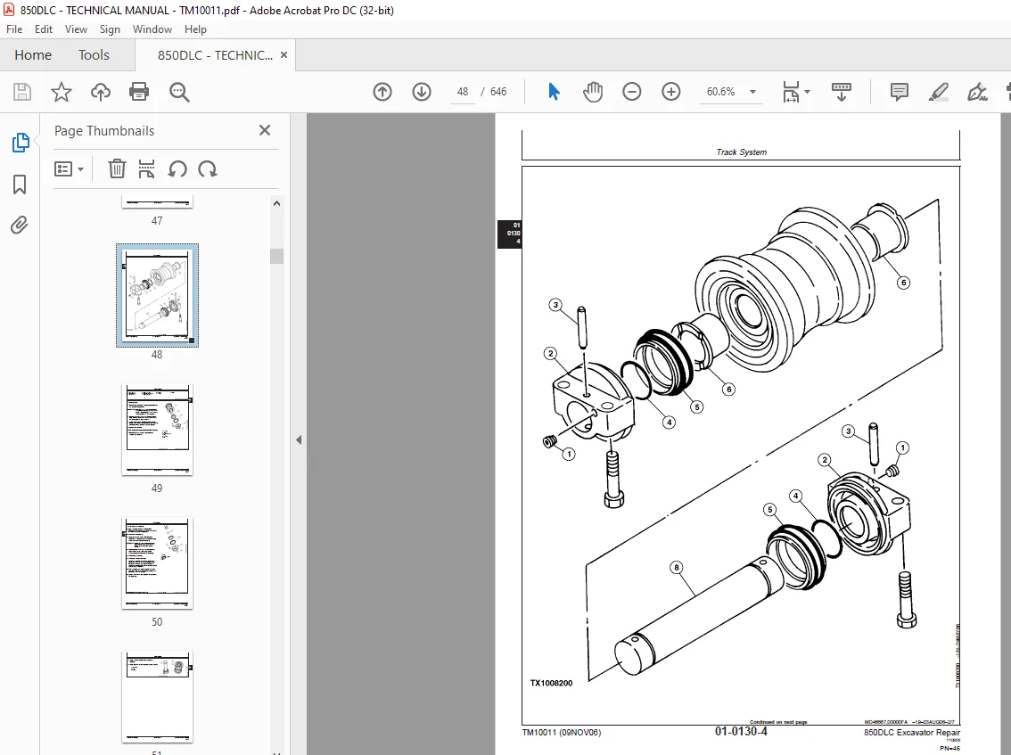
Track Roller Disassemble and Assemble 47
Track Roller Pressure Test 53
Track Carrier Roller Remove and Install 54
Track Carrier Roller Disassemble and Assemble 56
Metal Face Seal Inspection 57
Track Shoe Remove and Install 59
Track Chain Remove and Install 59
Track Chain Disassemble and Assemble 63
Track Chain Repair to Replace Broken Part 64
Sprocket Remove and Install 68
Front Idler Remove and Install 69
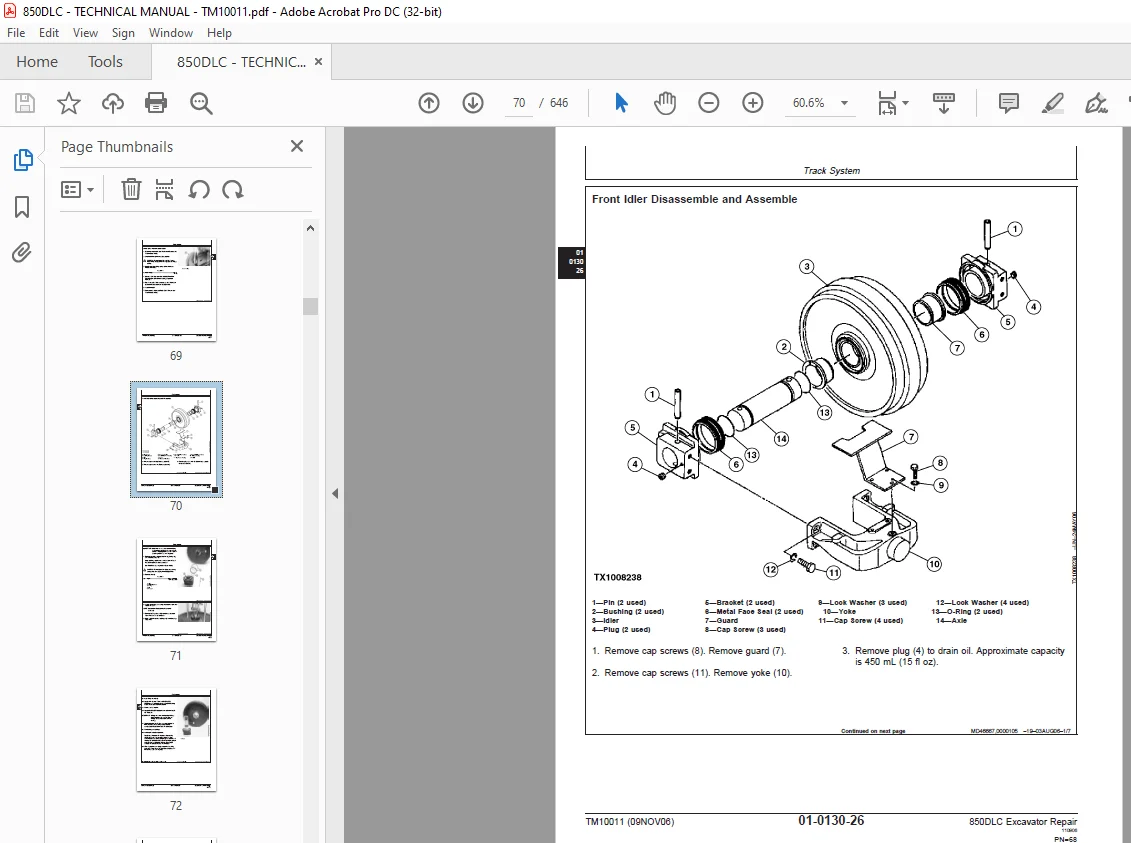
Front Idler Disassemble and Assemble 70
Front Idler Pressure Test 75
Track Adjuster and Recoil Spring Remove and Install 76
Track Adjuster and Recoil Spring Disassemble and Assemble 78
Track Adjuster Cylinder 81
Disassemble and Assemble 81
Axles, Differentials and Suspension Systems 83
Axle Shaft, Bearings, and Reduction Gears 85
Travel Gearbox Remove and Install 85
Travel Gearbox Disassemble and Assemble 88
Hydraulic System103
Travel Motor and Park Brake Remove and Install103
Travel Motor and Park Brake Disassemble and Assemble107
Counterbalance Valve Remove and Install112
Crossover Relief Valves Remove and Install113
Make-Up Check Valve Remove and Install113
Travel Speed Selector Valve Remove and Install113
Travel Motor and Park Brake Start-Up Procedure113
Engine115
Removal and Installation117
Engine Remove and Install117
Turbocharger Remove and Install121
Turbocharger Disassemble and Assemble124
Turbocharger Inspection132
Exhaust Manifold Remove and Install136
Upper Valve Cover Remove and Install137
Lower Valve Cover Remove and Install138
Rocker Arm Shaft Assembly Remove and Install140
Rocker Arm Shaft Assembly Disassemble and Assemble141
Rocker Arm Shaft Assembly Inspection142
Intake Manifold Remove and Install144
Lead Valve Remove and Install146
Water Pump Remove and Install147
Water Pump Disassemble and Assemble148
Cylinder Head Remove and Install151
Cylinder Head Disassemble and Assemble154
Cylinder Head Inspection163
Timing Gear Case Remove and Install169
Cylinder Block Disassemble and Assemble175
Cylinder Block Inspection177
Camshaft Remove and Install179
Camshaft Inspection180
Flywheel Remove and Install182
Flywheel Disassemble and Assemble184
Flywheel Housing Remove and Install186
Oil Pan Remove and Install188
Crankshaft Remove and Install189
Crankshaft Inspection194
Piston and Connecting Rod Remove and Install201
Piston and Connecting Rod Disassemble and Assemble204
Piston and Connecting Rod Inspection205
Engine Oil Pump Remove and Install211
Engine Oil Pump Disassemble and Assemble214
Engine Oil Pump Inspection216
Engine Oil Cooler Remove and Install218
Engine Oil Cooler Disassemble and Assemble220
Thermostat Housing Remove and Install222
Thermostat Remove and Install223
Thermostat Inspection224
Primary Exhaust Gas Recirculation (EGR) Cooler Remove and Install225
Secondary Exhaust Gas Recirculation (EGR) Cooler Remove and Install226
High Pressure Fuel Pump Remove and Install227
High Pressure Fuel Rail Remove and Install229
Fuel Injection Nozzle Remove and Install230
Starter Motor Remove and Install232
Serpentine Belt Remove and Install233
Alternator Remove and Install234
Engine Auxiliary System235
Cooling System237
Radiator Remove and Install237
Hydraulic Oil Cooler Remove and Install240
Intercooler Remove and Install240
Fuel Cooler Remove and Install241
Fan, Fan Guard, and Fan Shroud Remove and Install242
Coolant Recovery Tank Remove and Install243
Intake System245
Air Intake System Leakage Check245
Air Cleaner Remove and Install246
External Fuel Supply System247
Fuel Tank Remove and Install247
Primary Fuel Filter (Water Separator) Remove and Install249
Final Fuel Filter Remove and Install250
Dampener Drive (Flex Coupling)253
Elements255
Dampener Drive (Flex Coupling) Remove and Install255
Splitter Drive257
Removal and Installation259
Pump Drive Gearbox Remove and Install259
Gears, Shafts, and Bearings265
Pump Drive Gearbox Disassemble and Assemble265
Frame or Supporting Structure271
Frame Installation273
Welding On Machine273
Welding Repair of Major Structure274
Chassis Weights277
Counterweight Remove and Install277
Operator’s Station279
Removal and Installation281
Cab Remove and Install281
Operator Enclosure289
Sliding Windows Remove and Install289
Windowpanes Remove and Install290
Windowpane Dimensions291
Seat and Seat Belt309
Seat Remove and Install309
Seat Belt Remove and Install310
Air Suspension Seat Disassemble and Assemble312
Left and Right Console Covers Remove and Install314
Heating and Air Conditioning317
Refrigerant Cautions and Proper Handling317
Flush and Purge Air Conditioner System319
R134a Refrigerant Oil Information322
R134a Refrigerant Recovery/Recycling and Charging Station Installation Procedure323
Recover R134a Refrigerant324
Evacuate R134a System325
Charge R134a System326
Compressor Remove and Install326
Compressor Clutch Remove and Install328
Condenser Remove and Install330
Heater and Air Conditioner Remove and Install331
Receiver-Dryer Remove and Install334
Excavator335
Buckets337
Bucket Remove and Install337
Bucket Pin-Up Data340
Frames344
Bucket Links Remove and Install344
Arm Remove and Install345
Boom Remove and Install351
Inspect Pins, Bushings and Bosses—Front Attachment358
Bushings and Seal Remove and Install362
Hydraulic System365
Apply Vacuum to Hydraulic Oil Tank365
Hydraulic Circuit Pressure Release Procedure366
Pump 1 and 2 Remove and Install367
Pump 1 and 2 Disassemble and Assemble371
Pump 1 and 2 Inspection376
Pump 1 and 2 Start-Up Procedure378
Pump 1 and 2 Regulator Remove and Install380
Pump 1 and 2 Regulator Disassemble and Assemble382
Pilot Pump Remove and Install386
Pilot Pump Disassemble and Assemble387
Pilot Filter and Pressure Regulating Valve Remove and Install388
Pilot Filter and Pressure Regulating Valve Disassemble and Assemble390
Pilot Shutoff Solenoid Valve Remove and Install390
Pilot Shutoff Solenoid Valve Disassemble and Assemble392
Fan Drive Pump Remove and Install394
Fan Drive Pump Disassemble and Assemble398
Fan Drive Pump Regulator Remove and Install406
Fan Drive Pump Regulator Disassemble and Assemble408
Fan Drive Motor Remove and Install414
Fan Drive Motor Disassemble and Assemble438
Fan Drive Reversing Control Valve Disassemble and Assemble440
Fan Drive System Relief Valve Remove and Install442
Fan Drive Reversing Control Valve Remove and Install443
Solenoid Valve Manifold Remove and Install449
Solenoid Valve Remove and Install—Power Dig (SG), Travel Speed (SI), Boom Mode (SC) and Boom Flow Rate (SF)450
Pump Case Drain Filter and Bypass Valve Remove and Install452
Pilot Control Valve Remove and Install453
Pilot Control Valve Disassemble and Assemble458
Boom Up Shockless Valve Remove and Install465
Boom Up Shockless Valve Disassemble and Assemble468
Travel Pilot Control Valve Remove and Install469
Travel Pilot Control Valve Disassemble and Assemble472
Pilot Accumulator Remove and Install476
Pilot Check Valve Manifold Remove and Install479
Digging Sensor Manifold Remove and Install483
Travel Sensor Manifold Remove and Install485
Pilot Signal Manifold Remove and Install487
Pilot Signal Manifold Disassemble and Assemble490
Counterweight Pilot Control Valve Remove and Install493
Counterweight Pilot Control Valve Disassemble and Assemble496
Counterweight Slow Return Valve Remove and Install497
Counterweight Shutoff Valve Remove and Install499
Counterweight Check Valve Remove and Install501
Control Valve Remove and Install503
Control Valve Disassemble and Assemble507
Left Control Valve (5-Spool) Disassemble and Assemble508
Right Control Valve (4-Spool) Disassemble and Assemble520
Hydraulic Oil Tank Remove and Install530
Hydraulic Oil Tank Disassemble and Assemble534
Restriction Valve Remove and Install535
Hydraulic Oil Cooler Bypass Valve Remove and Install537
Hydraulic Oil Cooler Remove and Install539
Boom Cylinder Remove and Install541
Boom Cylinder Disassemble and Assemble546
Arm Cylinder Remove and Install551
Arm Cylinder Disassemble and Assemble555
Bucket Cylinder Remove and Install560
Bucket Cylinder Disassemble and Assemble566
Counterweight Cylinder Remove and Install571
Counterweight Cylinder Disassemble and Assemble573
Hydraulic Cylinder Bleed Procedure574
Swing or Pivoting System575
Mechanical Drive Elements577
Swing Gearbox Remove and Install577
Swing Gearbox Disassemble and Assemble580
Swing Gearbox Start-Up Procedure589
Upperstructure Remove and Install590
Swing Bearing Remove and Install592
Swing Bearing Disassemble and Assemble596
Swing Bearing Upper Seal Install599
Swing Bearing Lower Seal Install600
Hydraulic System601
Center Joint Remove and Install601
Center Joint Disassemble and Assemble604
Center joint608
Air test608
Swing Motor and Park Brake Remove and Install608
Swing Motor and Park Brake Disassemble and Assemble612
Swing Motor and Park Brake Start-Up Procedure620
Swing Motor Crossover Relief Valve Remove and Install620
Swing Motor Make-Up Check Valve Remove and Install621
Swing Park Release Valve Remove and Install622
Dealer Fabricated Tools625
Dealer Fabricated Tools627
DF1063 Lift Bracket627
DFT1130 Adapter629
DF1036A Propel Gearbox Nut Wrench630
DFT1109 Holding Bar631
Center Joint (Rotary Manifold) Lifting Tool632
DFT1119 Pump Support633
DFRW20 Compressor Holding Fixture635
DFT1250 Lifting Bracket636
Page Numbers 5
S.M 6/1/25