John Deere 850DLC Excavator Operation and Tests TECHNICAL MANUAL TM10009 – PDF DOWNLOAD
$34.95
John Deere 850DLC Excavator Operation and Tests TECHNICAL MANUAL TM10009 – PDF DOWNLOAD
Description
John Deere 850DLC Excavator Operation and Tests TECHNICAL MANUAL TM10009 – PDF DOWNLOAD
FILE DETAILS:
John Deere 850DLC Excavator Operation and Tests TECHNICAL MANUAL TM10009 – PDF DOWNLOAD
Language : English
Pages :962
Downloadable : Yes
File Type : PDF
IMAGES PREVIEW OF THE MANUAL:
DESCRIPTION:
John Deere 850DLC Excavator Operation and Tests TECHNICAL MANUAL TM10009 – PDF DOWNLOAD
Foreword
- This manual is written for an experienced technician. Essential tools required in performing certain service work are identified in this manual and are recommended for use. Live with safety: Read the safety messages in the introduction of this manual and the cautions presented throughout the text of the manual.
- This is the safety-alert symbol. When you see this symbol on the machine or in this manual, be alert to the potential for personal injury. Technical manuals are divided in two parts: repair and operation and tests. Repair sections tell how to repair the components.
- Operation and tests sections help you identify the majority of routine failures quickly. Information is organized in groups for the various components requiring service instruction. At the beginning of each group are summary listings of all applicable essential tools, service equipment and tools, other materials needed to do the job, service parts kits,
- specifications, wear tolerances, and torque values. Technical Manuals are concise guides for specific machines. They are on-the-job guides containing only the vital information needed for diagnosis, analysis, testing, and repair. Fundamental service information is available from other sources covering basic theory of operation, fundamentals of troubleshooting, general maintenance, and basic type of failures and their causes
TABLE OF CONTENTS:
John Deere 850DLC Excavator Operation and Tests TECHNICAL MANUAL TM10009 – PDF DOWNLOAD
Contents 5
General Information 7
Safety 9
Recognize Safety Information 9
Follow Safety Instructions 9
Operate Only If Qualified 9
Wear Protective Equipment 10
Avoid Unauthorized Machine Modifications 10
Add Cab Guarding for Special Uses 10
Inspect Machine 11
Stay Clear of Moving Parts 11
Avoid High-Pressure Oils 11
Beware of Exhaust Fumes 12
Prevent Fires 12
Prevent Battery Explosions 12
Handle Chemical Products Safely 13
Dispose of Waste Properly 13
Prepare for Emergencies 13
Use Steps and Handholds Correctly 13
Start Only From Operator’s Seat 14
Use and Maintain Seat Belt 14
Prevent Unintended Machine Movement 14
Avoid Work Site Hazards 15
Keep Riders Off Machine 15
Avoid Backover Accidents 16
Avoid Machine Tip Over 16
Use Special Care When Lifting Objects 16
Add and Operate Attachments Safely 17
Prevent Unintended Detonation of Explosive Devices 17
Park and Prepare for Service Safely 17
Service Cooling System Safely 18
Remove Paint Before Welding or Heating 18
Make Welding Repairs Safely 18
Drive Metal Pins Safely 18
Diagnostics 23
Main Controller (MCF) Diagnostic Trouble Codes 25
Main Controller (MCF) Diagnostic Trouble Codes 25
1100002 — Abnormal EEPROM 25
Controller Hardware Diagnostics 25
1100102 — Abnormal RAM 25
Controller Hardware Diagnostics 25
1100202 — Abnormal A/D Conversion 26
Controller Hardware Diagnostics 26
1100303 — Abnormal Sensor Voltage 27
Harness diagnostics 27
1100402 — CAN Communication Error 27
Controller Area Network (CAN) Diagnostics 27
1110103 — Engine Speed Dial sensor Circuit Voltage High Input 36
Engine Speed Dial Diagnostics 36
1110104 — Engine Speed Dial Sensor Circuit Voltage Low Input 37
Engine Speed Dial Diagnostics 38
1120003 — Pump 1 Delivery Pressure Sensor Circuit Voltage High 39
Pump 1 Delivery Pressure Sensor Diagnostics 39
1120004 — Pump 1 Delivery Pressure Sensor Voltage Low 41
Pump 1 Delivery Pressure Sensor Diagnostics 41
1120203 — Pump 2 Delivery Pressure Sensor Circuit Voltage High 43
Pump 2 Delivery Pressure Sensor Diagnostics 43
1120204 — Pump 2 Delivery Pressure Sensor Voltage Low 45
Pump 2 Delivery Pressure Sensor Diagnostics 45
1130103 — Swing Pilot Pressure Sensor Circuit Voltage High 47
Swing pilot pressure sensor diagnostics 47
1130104 — Swing Pilot Pressure Sensor Circuit Voltage Low 49
Swing Pilot Pressure Sensor Diagnostics 49
1130203 — Boom Raise Pilot Pressure Sensor Circuit Voltage High 51
Boom Up Pilot Pressure Sensor Diagnostics 51
1130204 — Boom Raise Pilot Pressure Sensor Circuit Voltage Low 53
Boom Up Pilot Pressure Sensor Diagnostics 53
1130303 — Arm Roll-in Pilot Pressure Sensor Circuit Voltage Hig 55
Arm In Pilot Pressure Sensor Diagnostics 55
1130304 — Arm Roll-in Pilot Pressure Sensor Circuit Voltage Low 57
Arm In Pilot Pressure Sensor Diagnostics 57
1140003 — Pump 2 (5-Spool) Control Solenoid Valve Feedback Curr 59
Pump 2 (5-Spool) Control Solenoid Diagnostics 59
1140004 — Pump 2 (5-Spool) Control Solenoid Valve Feedback Curr 60
Pump 2 (5-Spool) Control Solenoid Diagnostics 60
1140203 — Boom Flow Rate Solenoid (SF) Valve Feedback Current H 61
Boom Flow Rate Solenoid (SF) Diagnostics 61
1140204 — Boom Flow Rate Solenoid (SF) Valve Feedback Current L 62
Boom Flow Rate Solenoid (SF) Diagnostics 62
1140403 — Power Dig Solenoid (SG) Valve Feedback Current High 63
Power Dig Solenoid (SG) Diagnostics 63
1140404 — Power Dig Solenoid (SG) Valve Feedback Current Low 64
Power Dig Solenoid (SG) Diagnostics 64
1140503 — Travel Speed Solenoid (SI) Valve Current Feedback Hig 65
Travel Speed Solenoid (SI) Diagnostics 65
1140504 — Travel Speed Solenoid (SI) Valve Current Feedback Low 66
Travel Speed Solenoid (SI) Diagnostics 66
1141003 — Pump 1 (4-Spool) Control Solenoid Valve Feedback Curr 67
Pump 1 (4-Spool) Control Solenoid Diagnostics 67
1141004 — Pump 1 (4-Spool) Control Solenoid Valve Feedback Curr 68
Pump 1 (4-Spool) Control Solenoid Diagnostics 68
1141203 — Hydraulic Fan Pump Control Solenoid Valve Feedback Cu 69
Hydraulic Fan Pump Control Solenoid Diagnostics 69
1141204 — Hydraulic Fan Pump Solenoid Valve Feedback Current Lo 70
Hydraulic Fan Pump Control Solenoid Diagnostics 70
1180203 — Boom Pressure Sensor Circuit Voltage High 71
Boom Bottom Pressure Sensor Diagnostics 71
1180204 — Boom Pressure Sensor Circuit Voltage Low 73
Boom Bottom Pressure Sensor Diagnostics 73
1190103 — Hydraulic Oil Temperature Sensor Circuit Voltage High 75
Hydraulic Oil Temperature Sensor Diagnostics 75
1190104 — Hydraulic Oil Temperature Sensor Circuit Voltage Low 77
Hydraulic Oil Temperature Sensor Diagnostics 77
1191002 — Actual Engine Speed Message Error 79
Controller Area Network (CAN) Diagnostics 79
1191102 — Security Signal Message Error 88
Controller Area Network (CAN) Diagnostics 88
1191402 — Radiator Water Temperature Message Error 96
Controller Area Network (CAN) Diagnostics 96
1191802 — Work Mode Message Error104
Controller Area Network (CAN) Diagnostics 104
1192002 — Fuel Flow Rate Message Error113
Controller Area Network (CAN) Diagnostics 113
1197603 — Auxiliary Valve 2 Feedback Current High121
1197604 — Auxiliary Valve 2 Feedback Current Low121
1197703 — Auxiliary Valve 1 Feedback Current High121
1197704 — Auxiliary Valve 1 Feedback Current Low121
1198003 — ATT Relief Change Valve Feedback Current High121
1198004 — ATT Relief Change Valve Feedback Current Low121
1198103 — Fan Reversing Solenoid Valve 2 Feedback Current High121
Fan Reversing Solenoid 2 Diagnostics121
1198104 — Fan Reversing Solenoid Valve 2 Feedback Current Low122
Fan Reversing Solenoid 2 Diagnostics122
1198203 — Fan Reversing Solenoid Valve 1 Feedback Current High123
Fan Reversing Solenoid 1 Diagnostics123
1198204 — Fan Reversing Solenoid Valve 1 Feedback Current Low123
Fan Reversing Solenoid 1 Diagnostics123
1198302 — Intake Air Temperature Message Error124
Controller Area Network (CAN) Diagnostics 124
1198402 — Boost Temperature Message Error132
Controller Area Network (CAN) Diagnostics 132
1198903 — Boom Mode Solenoid (SC) Valve Feedback Current High141
Boom Mode Solenoid (SC) Diagnostics141
1198904 — Boom Mode Solenoid (SC) Valve Feedback Current Low141
Boom Mode Solenoid (SC) Diagnostics142
1199103 — Travel Right Pilot Pressure Sensor Circuit Voltage Hi142
Travel Right Pilot Pressure Sensor Diagnostics142
1199104 — Travel Right Pilot Pressure Sensor Circuit Voltage Lo144
Travel Right Pilot Pressure Sensor Diagnostics144
1199203 — Pump 2 (5-Spool) Control Pressure Sensor Circuit Volt146
Pump 2 (5-Spool) Control Pressure Sensor Diagnostics146
1199204 — Pump 2 (5-Spool) Control Pressure Sensor Circuit Volt148
Pump 2 (5-Spool) Control Pressure Sensor Diagnostics148
1199303 — Travel Left Pilot Pressure Sensor Circuit Voltage Hig150
Travel Left Pilot Pressure Sensor Diagnostics150
1199304 — Left Travel Pilot Pressure Sensor Circuit Low Input152
Travel Left Pilot Pressure Sensor Diagnostics152
1199403 — Pump 1 (4-Spool) Control Pressure Sensor Circuit Volt154
Pump 1 (4-Spool) Control Pressure Sensor Diagnostics154
1199404 — Pump 1 (4-Spool) Control Pressure Sensor Circuit Volt156
Pump 1 (4-Spool) Control Pressure Sensor Diagnostics156
1199503 — Arm Roll-Out Pilot Pressure Sensor Circuit Voltage Hi158
Arm Out Pilot Pressure Sensor Diagnostics158
1199504 — Arm Roll-Out Pilot Pressure Sensor Circuit Low Input160
Arm Out Pilot Pressure Sensor Diagnostics160
1199703 — Bucket Dump Pilot Pressure Sensor Circuit Voltage Hig162
Bucket Dump Pilot Pressure Sensor Diagnostics162
1199704 — Bucket Dump Pilot Pressure Sensor Circuit Voltage Low164
Bucket Dump Pilot Pressure Sensor Diagnostics164
1199803 — Boom Down Pilot Pressure Sensor Circuit Voltage High166
Boom Down Pilot Pressure Sensor Diagnostics166
1199804 — Boom Down Pilot Pressure Sensor Circuit Voltage Low168
Boom Down Pilot Pressure Sensor Diagnostics168
1199903 — Bucket Curl Pilot Pressure Sensor Circuit Voltage Hig170
Bucket Curl Pilot Pressure Sensor Diagnostics170
1199904 — Bucket Curl Pilot Pressure Sensor Circuit Voltage Low172
Bucket Curl Pilot Pressure Sensor Diagnostics172
Engine Control Module (ECM) Diagnostic Trouble Codes175
Engine Control Module (ECM) Diagnostic Trouble Codes175
9102 — Accelerator Sensor 1-2 Comparison (P1271)175
10003 — Engine Oil Pressure Sensor Voltage Low (P0522)175
10004 — Engine Oil Pressure Sensor Voltage High (P0523)175
10203 — Boost Pressure Sensor Voltage Low (P0237)175
10204 — Boost Pressure Sensor Voltage High (P0238)175
10503 — Boost Temperature Sensor Voltage High (P1113)175
10504 — Boost Temperature Sensor Voltage Low (P1112)175
10803 — Barometric Pressure Sensor Voltage Low (P0107)176
10804 — Barometric Pressure Sensor Voltage High (P0108)176
11003 — Engine Coolant Temperature Sensor Voltage High (P0118)176
11004 — Engine Coolant Temperature Sensor Voltage Low (P0117)176
15700 — Common Rail Pressure—First Stage (P088)176
15700 — Common Rail Pressure—Second Stage (P088)176
15702 — Common Rail Pressure High (P0089)176
15703 — Common Rail Pressure Sensor Voltage High (P0193) 176
15704 — Common Rail Pressure Sensor Voltage Low (P0192)177
17203 — Intake Air Temperature Sensor Voltage High (P0113)177
17204 — Intake Air Temperature Sensor Voltage Low (P0112)177
17403 — Fuel Temperature Sensor Voltage High (P0183)177
17404 — Fuel Temperature Sensor Voltage Low (P0182)177
19000 — Engine Overspeed (P0219)177
62802 — ROM Malfunction (P0601)177
63307 — Pressure Limiter Open (P1095)177
63602 — Camshaft Position Sensor (G-Sensor) Signal Missing (P03177
63602 — Camshaft Position Sensor (G-Sensor) Signal Mismatch (P0178
63607 — Camshaft Position Sensor (G-Sensor) out of Phase (P134178
63902 — CAN Communication Error (U2104)178
63903 — CAN Timeout (U2106)178
65103 — Open Circuit in Injection Nozzle #1 (P0201)178
65203 — Open Circuit in Injection Nozzle #2 (P0202)178
65303 — Open Circuit in Injection Nozzle #3 (P0203)178
65403 — Open Circuit in Injection Nozzle #4 (P0204) 178
65503 — Open Circuit in Injection Nozzle #5 (P0205)179
65603 — Open Circuit in Injection Nozzle #6 (P0206)179
72302 — Crankshaft Position Sensor Signal Missing (P0335)179
72302 — Crankshaft Sensor Mismatch (P0336)179
98703 — Check Engine Lamp Malfunction (P0650)179
107702 — CPU Fault Malfunction (P0606)179
107902 — 5 Volt Power Supply #1 Malfunction (P1631)179
108002 — 5 Volt Power Supply #2 Malfunction (P1632)179
123901 — No Pump Pressure—First Stage (P1094)180
124001 — No Pump Pressure Feed—Second Stage (P1093)180
134700 — PCV #1 Open Circuit or Short to Ground (P0092)180
134704 — PCV #1 Short to Power (P0091)180
134800 — PCV # 2 Open Circuit or Short to Ground (P1291)180
134804 — PCV #2 Short to Power (P1292)180
138103 — Fuel Filter Pressure Sensor Voltage High (P1294)180
138104 — Fuel Filter Pressure Sensor Voltage Low (P1293)180
148502 — Engine Control Module Relay Malfunction (P1625)181
1000103 — EGR Position Sensor Malfunction (P0487)181
1000202 — EGR Valve Control Malfunction (P0488)181
1000302 — Injection Nozzle Common #1 Malfunction (P1261)181
1000402 — Injection Nozzle Common #2 Malfunction (P1262)181
1000501 — Charge Circuit Malfunction—Bank 1 (P0611)181
1000601 — Charge Circuit Malfunction—Bank 2 (P0612)181
1000702 — CPU Monitoring IC Malfunction (P0606)181
1000802 — A/D Conversion Malfunction (P1630)182
1000902 — 5 Volt Power Supply #3 Malfunction (P1633)182
1001002 — 5 Volt Power Supply #4 Malfunction (P1634)182
1001102 — 5 Volt Power Supply #5 Malfunction (P1635)182
1001302 — EEPROM Malfunction (P0603)182
2010002 — Engine Coolant Temperature High182
2010102 — Engine Warning182
2011002 — Fuel Filter Restricted (Level 1)182
Fuel Filter Restriction Diagnostic Procedure182
2011002 — Fuel Filter Restricted (Level 2)183
Fuel Filter Restriction Diagnostic Procedure183
Information Controller (ICF) Diagnostic Trouble Codes185
Information Controller (ICF) Diagnostic Trouble Codes185
1400002 — Abnormal CAN Communication185
Controller Area Network (CAN) Diagnostics 185
1400102 — ICF: Flash Memory: Read/Write Error193
Controller Hardware Diagnostics193
1400202 — ICF: External RAM: Read/Write Error194
Controller Hardware Diagnostics194
1400302 — ICF: EEPROM: Sum Check Error195
Controller Hardware Diagnostics195
1400602 — ICF: Satellite Communication Terminal: Communication 196
1400802 — ICF: Abnormal Internal RAM196
Controller Hardware Diagnostics196
1410002 — Satellite Communication Terminal: Abnormal EEPROM196
1410102 — Satellite Communication Terminal: Abnormal IB/OB Queu196
1410202 — Satellite Communication Terminal: Abnormal Local Loop197
1410302 — Satellite Communication Terminal: The satellite is no197
1410402 — Satellite Communication Terminal: Fail 1 of Remote Lo197
1410502 — Satellite Communication Terminal: Fail 2 of Remote Lo197
1410602 — Satellite Communication Terminal: Sending and receivi197
Air Conditioner Controller (ACF) Diagnostic Trouble Codes199
Air Conditioner Controller (ACF) Diagnostic Trouble Codes199
E11 — Cab Air Temperature Sensor Open Circuit199
Harness Diagnostics199
E12 — Cab Air Temperature Sensor Short Circuit199
Harness Diagnostics199
E13 — Ambient Air Temperature Sensor Open Circuit200
Harness Diagnostics200
E14 — Ambient Air Temperature Sensor Short Circuit200
Harness Diagnostics200
E15 — Coolant Temperature Sensor Open Circuit201
Harness Diagnostics201
E16 — Coolant Temperature Sensor Short Circuit201
Harness Diagnostics202
E18 — Solar Sensor Abnormal202
Harness Diagnostics202
E21 — Freeze Control Switch Open Circuit203
Harness Diagnostics203
E22 — Freeze Control Switch Short Circuit203
Harness Diagnostics203
E43 — Abnormal Damper204
Harness Diagnostics204
E44 — Abnormal Damper204
Harness Diagnostics205
E45 — Abnormal Damper205
Harness Diagnostics205
E51 — Abnormal High/Low Pressure Switch206
Harness Diagnostics206
Monitor Controller (MON) Diagnostic Trouble Codes207
Monitor Controller (MON) Diagnostic Trouble Codes207
1330302 — Abnormal Thermister Temperature207
Monitor Temperature Diagnostics207
1330402 — Abnormal REG Input H Level207
Alternator Output Diagnostics207
1330602 — Abnormal EEPROM208
Information Controller Diagnostics208
1330802 — Abnormal CAN Communication208
Controller Area Network (CAN) Diagnostics 208
1331002 — Shorted circuit in Coolant Temperature Sensor217
Coolant Temperature Sensor Diagnostics217
1331103 — Shorted circuit in Fuel Level Sensor217
Fuel Level Sensor Diagnostics218
1331104 — Open circuit in Fuel Level Sensor218
Fuel Level Sensor Diagnostics219
Operational Checkout Procedure221
Operational Checkout Procedure223
Operational Checkout223
Diagnostic Trouble Codes Check223
Operational Checks—Key Switch Off, Engine Off Checks223
Operational Checks—Key Switch On, Engine Off Checks225
Operational Checks—Key Switch On, Engine On Checks233
Engine263
Theory of Operation265
Engine Component Location265
Engine Sampling Port Location266
Engine Fuel System Operation268
Engine Cooling System Operation273
Engine Lubrication System Operation274
Engine Intake and Exhaust System Operation276
Engine Turbocharger Operation277
Exhaust Gas Recirculation (EGR) Operation278
Quick On Start (QOS) System Operation279
Engine Speed Control System Operation280
Diagnostic Information283
Isuzu AH-6WG1XYSA-03283
Diagnose Engine Malfunctions283
Engine Cranks But Will Not Start284
Engine Cranks But Will Not Start Diagnostic Procedure284
Engine Misfires Or Runs Irregularly287
Engine Misfires Or Runs Irregularly Diagnostic Procedure287
Engine Does Not Develop Full Power291
Engine Does Not Develop Full Power Diagnostic Procedure291
Engine Overheats293
Engine Overheats Diagnostic Procedure294
Auto-Idle Does Not Work294
Auto-Idle Does Not Work Diagnostics Procedure294
Coolant Temperature Too Low296
Coolant Temperature Too Low Diagnostics Procedure296
Coolant in Oil or Oil in Coolant296
Coolant in Oil or Oil in Coolant Diagnostics Procedure296
Low Engine Oil Pressure297
Low Engine Oil Pressure Diagnostics Procedure297
High Engine Oil Pressure298
High Engine Oil Pressure Diagnostics Procedure298
Engine Uses Too Much Oil298
Engine Uses Too Much Oil Diagnostics298
Engine Uses Too Much Fuel299
Engine Uses Too Much Fuel Diagnostic Procedure299
Engine Emits Excessive White Exhaust Smoke301
Engine Emits Excessive White Exhaust Smoke Diagnostic Procedure301
Engine Emits Excessive Black or Gray Exhaust Smoke303
Engine Emits Excessive Black or Gray Exhaust Smoke Diagnostic Pr303
Turbocharger Excessively Noisy or Vibrates305
Turbocharger Excessively Noisy or Vibrates Diagnostics Procedure305
Oil Dripping From Turbocharger Adapter306
Oil Dripping From Turbocharger Adapter Diagnostics Procedure306
Excessive Drag in Turbocharger Rotating Members306
Excessive Drag in Turbocharger Rotating Members Diagnostics Proc306
Fuel In Oil307
Fuel In Oil Diagnostics Procedure307
Tests309
Serpentine Belt Tension Check309
Check and Adjust Injection Pump Timing309
Engine Valve Lash (Clearance) Check and Adjust312
Engine Compression Pressure Test315
Air Filter Restriction Indicator Switch Test316
Air Intake System Leakage Test316
Engine Power Test Using Turbocharger Boost Pressure317
Engine Oil Pressure Test319
Electrical System322
System Information323
Electrical Diagram Information323
System Diagrams333
Explanation of Wire Markings333
Fuse and Relay Specifications333
System Functional Schematic, Wiring Diagram, and Component Locat337
System Functional Schematic343
Cab Harness (W1) Component Location375
Cab Harness (W1) Wiring Diagram379
Machine Harness (W2) Component Location395
Machine Harness (W2) Wiring Diagram399
Monitor Harness (W3) Component Location413
Monitor Harness (W3) Wiring Diagram415
Engine Harness (W4) Component Location418
Engine Harness (W4) Wiring Diagram423
Engine Interface Harness (W5) Component Location431
Engine Interface Harness (W5) Wiring Diagram434
Air Conditioner Harness (W6) Component Location436
Air Conditioner Harness (W6) Wiring Diagram439
Control Valve Harness (W7) Component Location442
Control Valve Harness (W7) Wiring Diagram444
Pump Harness (W8) Component Location446
Pump Harness (W8) Wiring Diagram449
Auxiliary Fuse Box Harness (W9) Component Location452
Auxiliary Fuse Box Harness (W9) Wiring Diagram455
Cab Switch Harness (W10) Component Location457
Cab Switch Harness (W10) Wiring Diagram458
Pilot Shutoff Switch Harness (W11) Component Location459
Pilot Shutoff Switch Harness (W11) Wiring Diagram461
Heated Air Seat Harness (W12) Component Location464
Heated Air Seat Harness (W12) Wiring Diagram465
Seat Heater Switch Harness (W13) Component Location465
Seat Heater Switch Harness (W13) Wiring Diagram466
Multi-Function Pilot Control Lever Harness (W14) Component Locat468
Multi-Function Pilot Control Lever Harness (W14) Wiring Diagram471
Travel Alarm Cancel Switch Harness (W15) Component Location473
Travel Alarm Cancel Switch Harness (W15) Wiring Diagram473
Reversing Fan Switch Harness (W16) Component Location473
Reversing Fan Switch Harness (W16) Wiring Diagram474
Pilot Shutoff Valve Harness (W17) Component Location474
Pilot Shutoff Valve Harness (W17) Wiring Diagram475
Oil Cooler Harness (W20) Component Location476
Oil Cooler Harness (W20) Wiring Diagram477
Service Advisor Connector Harness (W22) Component Location478
Service Advisor Connector Harness (W22) Wiring Diagram480
JDLink™ System Harnesses (W50, W51, W52, W53, and W54) Component487
Machine Information Gateway (MIG) Harness (W50) Wiring Diagram—I491
GlobalTRACS® Terminal (GTT) Harness (W51) Wiring Diagram—If Equi495
JDLink™ CAN Harness (W52) Wiring Diagram—If Equipped498
JDLink™ Power Harness (W53) Wiring Diagram—If Equipped501
JDLink™ Jumper Harness (W54) Wiring Diagram—If Equipped504
JDLink™ Modular Telematics Gateway (MTG) Harness (W6002) Compone505
JDLink™ Modular Telematics Gateway (MTG) Harness (W6002) Wiring 507
Sub-System Diagnostics510
Controller Area Network (CAN) Theory of Operation510
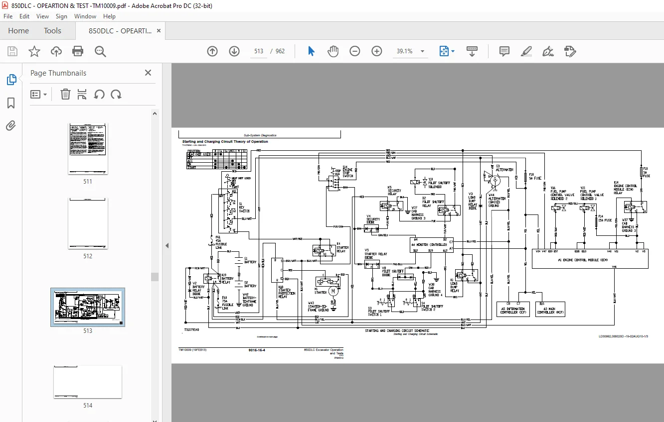
Starting and Charging Circuit Theory of Operation513
Quick On System (QOS) Preheat Circuit Theory of Operation518
Monitor Circuit Theory of Operation521
Engine Control Module (ECM) Circuit Theory of Operation529
Main Controller (MCF) Circuit Theory of Operation533
Information Controller (ICF) Theory of Operation551
Travel Alarm Circuit Theory of Operation554
Windshield Wiper and Washer Circuit Theory of Operation557
Pilot Shutoff Circuit Theory of Operation561
JDLink™ Circuit Theory of Operation—If Equipped564
Monitor Operation569
Monitor Menu Operation569
Monitor Service Menu Operation569
References571
Monitor Data Items571
Monitor Data Items Using the Monitor Display572
Reading Diagnostic Trouble Codes With Monitor Display573
JDLink™ Connection Procedure574
Service ADVISOR™ Diagnostic Application574
Service ADVISOR™ Connection Procedure575
Reading Diagnostic Trouble Codes With Service ADVISOR™ Diagnosti576
Service ADVISOR™ Interactive Tests578
Information Controller (ICF) Recorded Data579
Fuse Test581
Relay Test584
Pressure Sensor Test585
Solenoid Test586
Proportional Solenoid Test586
Alternator Test587
Electrical Component Checks587
Component Checks587
Battery Remove and Install595
Rear Cover Remove and Install596
Main Controller (MCF) Remove and Install597
Engine Control Module (ECM) Remove and Install598
Information Controller (ICF) Remove and Install599
Monitor Controller Remove and Install599
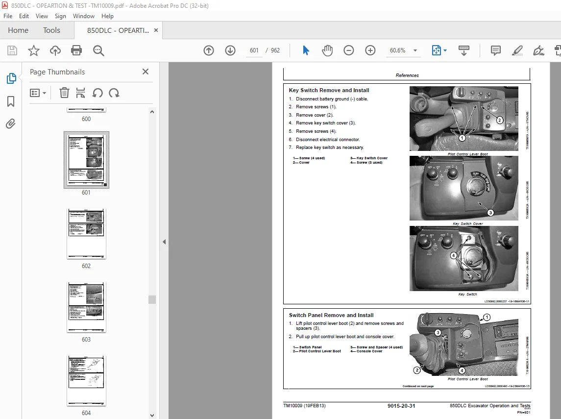
Key Switch Remove and Install601
Switch Panel Remove and Install601
Travel Alarm Remove and Install603
Left Console Switch Remove and Install603
Disconnect Tab Retainer Connectors604
Disconnecting Spring Wire Clip Connectors604
Replace DEUTSCH DEUTSCH is a trademark of the Deutsch Co™ Conne605
Replace DEUTSCHDEUTSCH is a trademark of Deutsch Co™ Rectangula606
Install DEUTSCH DEUTSCH is a trademark of the Deutsch Co™ Conta607
Replace WEATHER PACK WEATHER PACK is a trademark of Packard Elec608
Install WEATHER PACK WEATHER PACK is a trademark of Packard Elec609
Replace (Pull Type) Metri-Pack™ Connectors610
Replace (Push Type) Metri-Pack™ Connectors611
Replace CINCHCINCH is a trademark of the Cinch Co™ Connectors611
Install CINCHCINCH is a trademark of the Cinch Co™ Contact613
Repair 32 and 48 Way CINCHCINCH is a trademark of the Cinch Co™614
Remove Connector Body from Blade Terminals616
Power Train617
Theory of Operation619
Track Adjuster and Recoil Spring Operation619
Travel Gearbox Operation620
Diagnostic Information623
Diagnose Undercarriage Components Malfunctions623
Noisy or Loose Track Chain Diagnostic Procedure623
Tight Track Chain Diagnostic Procedure623
Frequent Track Chain Sag Adjustment Required Diagnostic Procedur624
Excessive Oil Leakage From Front Idler, Track Rollers, or Carrie624
Bent Track Shoes Diagnostic Procedure624
“Popping” Of Track Diagnostic Procedure625
Cracked Track Link Diagnostic Procedure626
Chipped Link Rails Diagnostic Procedure627
Individual Undercarriage Component Wear Diagnostic Procedure627
Measure Swing Bearing Wear628
Hydraulic System631
Theory of Operation633
Hydraulic System Diagram and Operation633
Fan Drive System Diagram and Operation635
Pilot System Diagram and Operation638
Pilot Check Valve Manifold and Accumulator Operation640
Boom Lowering With Engine Stopped Circuit Operation641
Pilot Pump, Pressure Regulating Valve, and Filter Operation644
Pilot Shutoff Solenoid Valve Operation645
Pilot Control Valve Operation648
Travel Pilot Control Valve Operation650
Boom Up Shockless Valve Operation651
Pilot Signal Manifold Operation652
Pilot Operation of Control Valve Operation659
Pump 1 and 2, Fan Drive Pump, and Gearbox Operation664
Pump 1 and 2 Regulator Operation667
Fan Drive Pump Regulator Operation671
Arm 2 Flow Rate Circuit Operation680
Control Valve Operation683
Control Valve Check Valves Identification and Operation696
Main Relief and Power Digging Valve Circuit Operation699
Circuit Relief and Anticavitation Valve Operation704
Travel Flow Combiner Valve Circuit Operation706
Boom Regenerative Valve Circuit Operation708
Arm Regenerative Valve Circuit Operation710
Bucket Regenerative Valve Circuit Operation712
Boom and Arm Reduced Leakage Valves Operation714
Boom Flow Rate Circuit Operation718
Boom Mode Circuit Operation724
Counterweight Removal Circuit Operation727
Swing Gearbox Operation727
Swing Motor and Park Brake Circuit Operation728
Swing Motor Park Brake Release Circuit Operation731
Center Joint Operation732
Travel Motor and Park Brake Circuit Operation733
Travel Motor Speed Circuit Operation735
Boom, Arm, and Bucket Cylinder Operation737
Counterweight Removal Cylinder Operation738
Return Filter Operation739
Diagnostic Information741
Diagnose No Hydraulics Malfunctions741
No Hydraulic Functions Diagnostic Procedure741
Diagnose All Hydraulics Slow Malfunctions743
All Hydraulic Functions Slow Diagnostic Procedure743
Poor Combined Operation Diagnostic Procedure745
Diagnose All Hydraulic Functions Too Fast Malfunctions746
Hydraulic Function Speed Too Fast Diagnostic Procedure747
Diagnose Hydraulic Overheating Malfunctions747
Hydraulic Oil Overheats Diagnostic Procedure747
Diagnose Fan Drive Hydraulic System Malfunctions749
Cooling Fan Remains At Low Speed749
Cooling Fan Remains At Maximum Speed750
Diagnose Pilot Circuit Malfunctions751
All Functions Cannot Be Operated Diagnostic Procedure751
Function Does Not Stop When Control Lever Released Diagnostic Pr752
Some Functions Cannot Be Operated, All Others Are Normal Diagnos753
All Functions Slow Diagnostic Procedure754
Function Moves in Opposite Direction Diagnostic Procedure755
Diagnose Dig Circuit Malfunctions756
All Hydraulic Functions Low Power Diagnostic Procedure756
Boom Raise Power Is Low During Digging Diagnostic Procedure756
Some Functions Cannot Be Operated or Are Slow, Travel And Swing 757
Arm Or Bucket Speeds Are Slow During Combined Function With Boom759
During Combined Functions, Boom Raise Speed Is Slow And Arm-In I760
Boom Mode Switch Off, Boom Will Not Raise Machine Off Ground Dia761
Load Falls When Control Valve Is Actuated To Raise Load With Eng763
Load Drifts Down When Control Valve Is In Neutral Position Diagn764
Dig Function Speed Is Slow During Combined Operation With Swing 766
Dig Function Speed Is Slow During Combined Operation With Swing 767
HP (High Power) Function Does Not Operate, P (Standard) Mode Is 768
Diagnose Swing Circuit Malfunctions770
Swing Speed Slow In Both Directions Diagnostic Procedure770
Swing Speed Slow or Does Not Operate In One Direction Diagnostic772
Swing Is Too Fast Diagnostic Procedure774
Upperstructure Drift With Swing Valve In Neutral Diagnostic Proc775
Swing Function Does Not Operate Diagnostic Procedure775
Diagnose Travel Circuit Malfunctions776
Left Travel Does Not Move During Single Travel Operation Diagnos777
Right Travel Does Not Move During Single Travel Operation Diagno779
Both Tracks Do Not Rotate Or Move Slowly In Either Direction Dia780
One Track Does Not Rotate Or Moves Slowly Diagnostic Procedure781
Machine Mistracks During Combined Operation With Dig Functions D784
Travel Mode Will Not Switch From Slow To Fast Speed Diagnostic P785
Travel Park Brakes Do Not Apply Diagnostic Procedure787
Track Will Not Move In One Direction Diagnostic Procedure787
Track Will Not Move In Either Direction Diagnostic Procedure789
Machine Mistracks At All Speeds In Both Directions Diagnostic Pr790
Slow Travel Speed Or Low Power Diagnostic Procedure792
Combined Travel And Dig Functions Slow Or No Power Diagnostic Pr794
Travel Is “Jerky” Diagnostic Procedure795
Machine Will Not Hold Back And Park Brakes Engage And Disengage 796
Machine Will Not Turn Smoothly In One Direction Or Park Brake Gr796
Diagnose Counterweight Removal System Malfunctions796
Counterweight Removal / Installation Device Does Not Operate Or 796
Counterweight Removal / Installation Speed Is Too Fast Diagnosti798
Diagnose Auto Lubrication System Malfunctions799
Auto Lubrication Does Not Operate Diagnostic Procedure800
Auto Lubrication Does Not Stop Diagnostic Procedure802
Auto Lubrication Alarm Is Displayed Diagnostic Procedure802
Pump 1, Pump 2, Fan Drive Pump, and Pilot Pump Line Connections804
Control Valve Line Identification805
Swing Motor Line Identification807
Control Lever Pattern Conversion808
Pilot Control Valve-to-Pilot Signal Manifold Component Location—813
Pilot Control Valve-to-Pilot Signal Manifold Component Location—817
Pilot Signal Manifold-to-Control Valve Line Connections821
Travel Hydraulic System Component Location825
Travel Hydraulic System Line Connections829
Fan Drive System Component Location833
Fan Drive System Line Connections835
Hydraulic System Component Location840
Hydraulic System Line Connections841
Counterweight Removal Hydraulic System Component Location843
Counterweight Removal Hydraulic System Line Connections843
Hydraulic System Schematic843
Tests875
Hydraulic Test Port Location875
JT05800 Digital Thermometer Installation875
JT02156A Digital Pressure/Temperature Analyzer Installation876
Hydraulic Oil Cleanup Procedure Using Portable Filter Caddy877
Hydraulic Oil Warm-Up Procedure878
Pilot Pressure Regulating Valve Test and Adjustment880
Control Valve Spool Actuating Pilot Pressure Test882
Power Dig Solenoid Valve (port SG) Test and Adjustment884
Travel Speed Solenoid Valve (port SI) Test and Adjustment886
Boom Mode Solenoid Valve (port SC) Test and Adjustment888
Boom Flow Rate Solenoid Valve (port SF) Test and Adjustment890
Main Relief and Power Digging Valve Test and Adjustment892
Circuit Relief Valve Test and Adjustment895
Boom Mode Relief Valve Test and Adjustment899
Pump Servo Piston Minimum Flow Test and Adjustment901
Pump Servo Piston Maximum Flow Test and Adjustment903
Pump Flow Rate (Displacement) Test and Adjustment905
Swing Motor Crossover Relief Valve Test and Adjustment906
Travel Motor Crossover Relief Valve Test and Adjustment908
Swing Motor Leakage Test910
Travel Motor Leakage Test912
Cylinder Drift Test—Arm, Boom, and Bucket913
Pump Flow Test914
Fan Speed Test917
Fan Motor Case Drain Test918
Fan Drive Pump Flow Test920
Fan Drive System Relief Valve Test and Adjustment924
Fan Drive Pump Servo Piston Minimum Flow Test and Adjustment926
Fan Drive Pump Servo Piston Maximum Flow Test and Adjustment926
Fan Drive Pump Flow Rate Test and Adjustment927
Fan Drive Pump Torque Control Test and Adjustment928
Heating and Air Conditioning System929
Theory Of Operation931
Air Conditioning System Cycle of Operation931
Diagnostic Information933
Diagnose Air Conditioning System Malfunctions933
Diagnose Heating System Malfunctions936
Air Conditioner and Heater Diagnostic Trouble Code Check937
Heater and Air Conditioner Component Location939
Tests943
Refrigerant Cautions and Proper Handling943
Heating and Air Conditioning Operational Checks943
Visual Inspection of Components943
R134a Air Conditioning System Test945
Air Conditioner Compressor Clutch Test945
Refrigerant Leak Test945
Refrigerant Hoses and Tubing Inspection946
Air Conditioner Compressor Belt Check and Adjustment946
Operating Pressure Diagnostic Chart946
Reference Material947
Terminology Cross Reference Chart949
Terminology Cross Reference Chart949
Page Number 5
Section 9000 7
Group 01 9
Section 9001 23
Group 10 25
Group 20175
Group 30185
Group 40199
Group 50207
Section 9005221
Group 10223
Section 9010263
Group 05265
Group 15283
Group 25309
Section 9015322
Group 05323
Group 10333
Group 15510
Group 16569
Group 20571
Section 9020617
Group 05619
Group 15623
Section 9025631
Group 05633
Group 15741
Group 25875
Section 9031929
Group 05931
Group 15933
Group 25943
Section 9050947
Group 05949
S.M 6/1/25