John Deere 850DLC Excavator Operation and Tests TECHNICAL MANUAL TM10009 – PDF DOWNLOAD
$36.95
John Deere 850DLC Excavator Operation and Tests TECHNICAL MANUAL TM10009 – PDF DOWNLOAD
Description
John Deere 850DLC Excavator Operation and Tests TECHNICAL MANUAL TM10009 – PDF DOWNLOAD
FILE DETAILS:
John Deere 850DLC Excavator Operation and Tests TECHNICAL MANUAL TM10009 – PDF DOWNLOAD
Language : English
Pages :990
Downloadable : Yes
File Type : PDF
IMAGES PREVIEW OF THE MANUAL:
DESCRIPTION:
John Deere 850DLC Excavator Operation and Tests TECHNICAL MANUAL TM10009 – PDF DOWNLOAD
Foreword
- This manual is written for an experienced technician. Essential tools required in performing certain service work are identified in this manual and are recommended for use.
- Live with safety: Read the safety messages in the introduction of this manual and the cautions presented throughout the text of the manual. This is the safety-alert symbol. When you see this symbol on the machine or in this manual, be alert to the potential for personal injury.
- Technical manuals are divided in two parts: repair and operation and tests. Repair sections tell how to repair the components. Operation and tests sections help you identify the majority of routine failures quickly. Information is organized in groups for the various components requiring service instruction.
- At the beginning of each group are summary listings of all applicable essential tools, service equipment and tools, other materials needed to do the job, service parts kits, specifications, wear tolerances, and torque values. Technical Manuals are concise guides for specific machines. They are on-the-job guides containing only the vital information needed for diagnosis, analysis, testing, and repair. Fundamental service information is available from other sources covering basic theory of operation, fundamentals of troubleshooting, general maintenance, and basic type of failures and their causes.
TABLE OF CONTENTS:
John Deere 850DLC Excavator Operation and Tests TECHNICAL MANUAL TM10009 – PDF DOWNLOAD
Contents 5
General Information 7
Safety 9
Recognize Safety Information 9
Follow Safety Instructions 9
Operate Only If Qualified 9
Wear Protective Equipment 10
Avoid Unauthorized Machine Modifications 10
Add Cab Guarding for Special Uses 11
Inspect Machine 11
Stay Clear of Moving Parts 11
Avoid High-Pressure Oils 12
Beware of Exhaust Fumes 12
Prevent Fires 13
Prevent Battery Explosions 13
Handle Chemical Products Safely 14
Dispose of Waste Properly 14
Prepare for Emergencies 14
Use Steps and Handholds Correctly 15
Start Only From Operator’s Seat 15
Use and Maintain Seat Belt 15
Prevent Unintended Machine Movement 16
Avoid Work Site Hazards 16
Keep Riders Off Machine 17
Avoid Backover Accidents 17
Avoid Machine Tip Over 18
Use Special Care When Lifting Objects 18
Add and Operate Attachments Safely 19
Prevent Unintended Detonation of Explosive Devices 19
Park and Prepare for Service Safely 20
Service Cooling System Safely 20
Remove Paint Before Welding or Heating 21
Make Welding Repairs Safely 21
Drive Metal Pins Safely 22
Diagnostics 23
Main Controller (MCF) Diagnostic Trouble Codes 29
Main Controller (MCF) Diagnostic Trouble Codes 29
1100002 — Abnormal EEPROM 29
Controller Hardware Diagnostics 29
29
30
1100102 — Abnormal RAM 30
Controller Hardware Diagnostics 30
30
31
1100202 — Abnormal A/D Conversion 31
Controller Hardware Diagnostics 31
31
32
1100303 — Abnormal Sensor Voltage 32
Harness diagnostics 32
32
32
1100402 — CAN Communication Error 33
Controller Area Network (CAN) Diagnostics 33
33
33
33
34
34
34
35
35
35
35
36
36
36
36
37
37
37
37
38
38
38
38
38
39
39
39
39
39
1110103 — Engine Speed Dial sensor Circuit Voltage High Input 40
Engine Speed Dial Diagnostics 40
40
40
40
41
41
41
1110104 — Engine Speed Dial Sensor Circuit Voltage Low Input 42
Engine Speed Dial Diagnostics 42
42
42
42
43
43
43
1120003 — Pump 1 Delivery Pressure Sensor Circuit Voltage High 44
Pump 1 Delivery Pressure Sensor Diagnostics 44
44
44
44
45
45
1120004 — Pump 1 Delivery Pressure Sensor Voltage Low 45
Pump 1 Delivery Pressure Sensor Diagnostics 46
46
46
46
47
47
1120203 — Pump 2 Delivery Pressure Sensor Circuit Voltage High 47
Pump 2 Delivery Pressure Sensor Diagnostics 48
48
48
48
49
49
1120204 — Pump 2 Delivery Pressure Sensor Voltage Low 49
Pump 2 Delivery Pressure Sensor Diagnostics 50
50
50
50
51
51
1130103 — Swing Pilot Pressure Sensor Circuit Voltage High 51
Swing pilot pressure sensor diagnostics 52
52
52
52
53
53
1130104 — Swing Pilot Pressure Sensor Circuit Voltage Low 53
Swing Pilot Pressure Sensor Diagnostics 54
54
54
54
55
55
1130203 — Boom Raise Pilot Pressure Sensor Circuit Voltage High 55
Boom Up Pilot Pressure Sensor Diagnostics 56
56
56
56
57
57
1130204 — Boom Raise Pilot Pressure Sensor Circuit Voltage Low 57
Boom Up Pilot Pressure Sensor Diagnostics 58
58
58
58
59
59
1130303 — Arm Roll-in Pilot Pressure Sensor Circuit Voltage High 59
Arm In Pilot Pressure Sensor Diagnostics 60
60
60
60
61
61
1130304 — Arm Roll-in Pilot Pressure Sensor Circuit Voltage Low 61
Arm In Pilot Pressure Sensor Diagnostics 62
62
62
62
63
63
1140003 — Pump 2 (5-Spool) Control Solenoid Valve Feedback Current High 63
Pump 2 (5-Spool) Control Solenoid Diagnostics 64
64
64
64
1140004 — Pump 2 (5-Spool) Control Solenoid Valve Feedback Current Low 65
Pump 2 (5-Spool) Control Solenoid Diagnostics 65
65
65
66
1140203 — Boom Flow Rate Solenoid (SF) Valve Feedback Current High 66
Boom Flow Rate Solenoid (SF) Diagnostics 66
66
66
67
1140204 — Boom Flow Rate Solenoid (SF) Valve Feedback Current Low 67
Boom Flow Rate Solenoid (SF) Diagnostics 67
67
67
68
1140403 — Power Dig Solenoid (SG) Valve Feedback Current High 68
Power Dig Solenoid (SG) Diagnostics 68
68
68
69
1140404 — Power Dig Solenoid (SG) Valve Feedback Current Low 69
Power Dig Solenoid (SG) Diagnostics 69
69
69
70
1140503 — Travel Speed Solenoid (SI) Valve Current Feedback High 70
Travel Speed Solenoid (SI) Diagnostics 70
70
70
71
1140504 — Travel Speed Solenoid (SI) Valve Current Feedback Low 71
Travel Speed Solenoid (SI) Diagnostics 71
71
71
72
1141003 — Pump 1 (4-Spool) Control Solenoid Valve Feedback Current High 72
Pump 1 (4-Spool) Control Solenoid Diagnostics 72
72
73
73
1141004 — Pump 1 (4-Spool) Control Solenoid Valve Feedback Current Low 73
Pump 1 (4-Spool) Control Solenoid Diagnostics 73
74
74
74
1141203 — Hydraulic Fan Pump Control Solenoid Valve Feedback Current High 74
Hydraulic Fan Pump Control Solenoid Diagnostics 75
75
75
75
1141204 — Hydraulic Fan Pump Solenoid Valve Feedback Current Low 75
Hydraulic Fan Pump Control Solenoid Diagnostics 76
76
76
76
1180203 — Boom Pressure Sensor Circuit Voltage High 76
Boom Bottom Pressure Sensor Diagnostics 77
77
77
77
78
78
1180204 — Boom Pressure Sensor Circuit Voltage Low 78
Boom Bottom Pressure Sensor Diagnostics 79
79
79
79
80
80
1190103 — Hydraulic Oil Temperature Sensor Circuit Voltage High 80
Hydraulic Oil Temperature Sensor Diagnostics 81
81
81
82
82
1190104 — Hydraulic Oil Temperature Sensor Circuit Voltage Low 82
Hydraulic Oil Temperature Sensor Diagnostics 83
83
83
84
84
1191002 — Actual Engine Speed Message Error 84
Controller Area Network (CAN) Diagnostics 85
85
85
85
86
86
86
87
87
87
87
88
88
88
88
89
89
89
89
90
90
90
90
90
91
91
91
91
91
1191102 — Security Signal Message Error 92
Controller Area Network (CAN) Diagnostics 92
92
92
92
93
93
93
94
94
94
94
95
95
95
95
96
96
96
96
97
97
97
97
97
98
98
98
98
98
1191402 — Radiator Water Temperature Message Error 99
Controller Area Network (CAN) Diagnostics 99
99
99
100
100
100
101
101
101
101
102
102
102
102
103
103
103
103
104
104
104
104
105
105
105
105
105
106
106
1191802 — Work Mode Message Error106
Controller Area Network (CAN) Diagnostics 106
106
106
107
107
107
108
108
108
108
109
109
109
109
110
110
110
110
111
111
111
111
112
112
112
112
112
113
113
1192002 — Fuel Flow Rate Message Error113
Controller Area Network (CAN) Diagnostics 113
113
113
114
114
114
115
115
115
115
116
116
116
116
117
117
117
117
118
118
118
118
119
119
119
119
119
120
120
1197603 — Auxiliary Valve 2 Feedback Current High120
1197604 — Auxiliary Valve 2 Feedback Current Low120
1197703 — Auxiliary Valve 1 Feedback Current High121
1197704 — Auxiliary Valve 1 Feedback Current Low121
1198003 — ATT Relief Change Valve Feedback Current High121
1198004 — ATT Relief Change Valve Feedback Current Low121
1198103 — Fan Reversing Solenoid Valve 2 Feedback Current High122
Fan Reversing Solenoid 2 Diagnostics122
122
122
1198104 — Fan Reversing Solenoid Valve 2 Feedback Current Low122
Fan Reversing Solenoid 2 Diagnostics122
123
123
1198203 — Fan Reversing Solenoid Valve 1 Feedback Current High123
Fan Reversing Solenoid 1 Diagnostics123
123
124
1198204 — Fan Reversing Solenoid Valve 1 Feedback Current Low124
Fan Reversing Solenoid 1 Diagnostics124
124
124
1198302 — Intake Air Temperature Message Error124
Controller Area Network (CAN) Diagnostics 125
125
125
125
126
126
126
127
127
127
127
128
128
128
128
129
129
129
129
130
130
130
130
130
131
131
131
131
131
1198402 — Boost Temperature Message Error132
Controller Area Network (CAN) Diagnostics 132
132
132
132
133
133
133
134
134
134
134
135
135
135
135
136
136
136
136
137
137
137
137
137
138
138
138
138
138
1198903 — Boom Mode Solenoid (SC) Valve Feedback Current High139
Boom Mode Solenoid (SC) Diagnostics139
139
139
139
1198904 — Boom Mode Solenoid (SC) Valve Feedback Current Low140
Boom Mode Solenoid (SC) Diagnostics140
140
140
140
1199103 — Travel Right Pilot Pressure Sensor Circuit Voltage High141
Travel Right Pilot Pressure Sensor Diagnostics141
141
141
141
142
142
1199104 — Travel Right Pilot Pressure Sensor Circuit Voltage Low142
Travel Right Pilot Pressure Sensor Diagnostics143
143
143
143
144
144
1199203 — Pump 2 (5-Spool) Control Pressure Sensor Circuit Voltage High144
Pump 2 (5-Spool) Control Pressure Sensor Diagnostics145
145
145
145
146
146
1199204 — Pump 2 (5-Spool) Control Pressure Sensor Circuit Voltage Low147
Pump 2 (5-Spool) Control Pressure Sensor Diagnostics147
147
147
147
148
148
1199303 — Travel Left Pilot Pressure Sensor Circuit Voltage High149
Travel Left Pilot Pressure Sensor Diagnostics149
149
149
149
150
150
1199304 — Left Travel Pilot Pressure Sensor Circuit Low Input150
Travel Left Pilot Pressure Sensor Diagnostics151
151
151
151
152
152
1199403 — Pump 1 (4-Spool) Control Pressure Sensor Circuit Voltage High152
Pump 1 (4-Spool) Control Pressure Sensor Diagnostics153
153
153
153
154
154
1199404 — Pump 1 (4-Spool) Control Pressure Sensor Circuit Voltage Low154
Pump 1 (4-Spool) Control Pressure Sensor Diagnostics155
155
155
155
156
156
1199503 — Arm Roll-Out Pilot Pressure Sensor Circuit Voltage High156
Arm Out Pilot Pressure Sensor Diagnostics157
157
157
157
158
158
1199504 — Arm Roll-Out Pilot Pressure Sensor Circuit Low Input158
Arm Out Pilot Pressure Sensor Diagnostics159
159
159
159
160
160
1199703 — Bucket Dump Pilot Pressure Sensor Circuit Voltage High160
Bucket Dump Pilot Pressure Sensor Diagnostics161
161
161
161
162
162
1199704 — Bucket Dump Pilot Pressure Sensor Circuit Voltage Low162
Bucket Dump Pilot Pressure Sensor Diagnostics163
163
163
163
164
164
1199803 — Boom Down Pilot Pressure Sensor Circuit Voltage High164
Boom Down Pilot Pressure Sensor Diagnostics165
165
165
165
166
166
1199804 — Boom Down Pilot Pressure Sensor Circuit Voltage Low166
Boom Down Pilot Pressure Sensor Diagnostics167
167
167
167
168
168
1199903 — Bucket Curl Pilot Pressure Sensor Circuit Voltage High168
Bucket Curl Pilot Pressure Sensor Diagnostics169
169
169
169
170
170
1199904 — Bucket Curl Pilot Pressure Sensor Circuit Voltage Low170
Bucket Curl Pilot Pressure Sensor Diagnostics171
171
171
171
172
172
Engine Control Module (ECM) Diagnostic Trouble Codes173
Engine Control Module (ECM) Diagnostic Trouble Codes173
9102 — Accelerator Sensor 1-2 Comparison (P1271)173
10003 — Engine Oil Pressure Sensor Voltage Low (P0522)174
10004 — Engine Oil Pressure Sensor Voltage High (P0523)174
10203 — Boost Pressure Sensor Voltage Low (P0237)174
10204 — Boost Pressure Sensor Voltage High (P0238)174
10503 — Boost Temperature Sensor Voltage High (P1113)175
10504 — Boost Temperature Sensor Voltage Low (P1112)175
10803 — Barometric Pressure Sensor Voltage Low (P0107)175
10804 — Barometric Pressure Sensor Voltage High (P0108)175
11003 — Engine Coolant Temperature Sensor Voltage High (P0118)176
11004 — Engine Coolant Temperature Sensor Voltage Low (P0117)176
15700 — Common Rail Pressure—First Stage (P088)176
15700 — Common Rail Pressure—Second Stage (P088)176
15702 — Common Rail Pressure High (P0089)177
15703 — Common Rail Pressure Sensor Voltage High (P0193) 177
15703 — Common Rail Pressure Sensor Voltage Low (P0192)177
17203 — Intake Air Temperature Sensor Voltage High (P0113)178
17204 — Intake Air Temperature Sensor Voltage Low (P0112)178
17403 — Fuel Temperature Sensor Voltage High (P0183)178
17404 — Fuel Temperature Sensor Voltage Low (P0182)178
19000 — Engine Overspeed (P0219)179
62802 — ROM Malfunction (P0601)179
63307 — Pressure Limiter Open (P0601)179
63602 — Camshaft Position Sensor (G-Sensor) Signal Missing (P0340)179
63602 — Camshaft Position Sensor (G-Sensor) Signal Mismatch (P0341)180
63607 — Camshaft Position Sensor (G-Sensor) out of Phase (P1345)180
63902 — CAN Communication Error (U2104)180
63903 — CAN Timeout (U2106)180
65103 — Open Circuit in Injection Nozzle #1 (P0201)181
65203 — Open Circuit in Injection Nozzle #2 (P0202)181
65303 — Open Circuit in Injection Nozzle #3 (P0203)181
65403 — Open Circuit in Injection Nozzle #4 (P0204) 181
65503 — Open Circuit in Injection Nozzle #5 (P0205)182
65603 — Open Circuit in Injection Nozzle #6 (P0206)182
72302 — Crankshaft Position Sensor Signal Missing (P0335)182
72302 — Crankshaft Sensor Mismatch (P0336)182
98703 — Check Engine Lamp Malfunction (P0650)183
107702 — CPU Fault Malfunction (P0606)183
107902 — 5 Volt Power Supply #1 Malfunction (P1631)183
108002 — 5 Volt Power Supply #2 Malfunction (P1632)183
123901 — No Pump Pressure—First Stage (P1094)184
124001 — No Pump Pressure Feed—Second Stage (P1093)184
134700 — PCV #1 Open Circuit or Short to Ground (P0092)184
134704 — PCV #1 Short to Power (P0091)184
134800 — PCV # 2 Open Circuit or Short to Ground (P1291)185
134804 — PCV #2 Short to Power (P1292)185
148502 — Engine Control Module Relay Malfunction (P1625)185
1000103 — EGR Position Sensor Malfunction (P0487)186
1000202 — EGR Valve Control Malfunction (P0488)186
1000302 — Injection Nozzle Common #1 Malfunction (P1261)186
1000402 — Injection Nozzle Common #2 Malfunction (P1262)186
1000501 — Charge Circuit Malfunction—Bank 1 (P0611)187
1000601 — Charge Circuit Malfunction—Bank 2 (P0612)187
1000702 — CPU Monitoring IC Malfunction (P0606)187
1000802 — A/D Conversion Malfunction (P1630)187
1000902 — 5 Volt Power Supply #3 Malfunction (P1633)188
1001002 — 5 Volt Power Supply #4 Malfunction (P1634)188
1001102 — 5 Volt Power Supply #5 Malfunction (P1635)188
1001302 — EEPROM Malfunction (P0603)188
Information Controller (ICF) Diagnostic Trouble Codes189
Information Controller (ICF) Diagnostic Trouble Codes189
1400002 — Abnormal CAN Communication189
1400102 — ICF: Flash Memory: Read/Write Error189
1400202 — ICF: External RAM: Read/Write Error190
1400302 — ICF: EEPROM: Sum Check Error190
1400602 — ICF: Satellite Communication Terminal: Communication Error190
1400802 — ICF: Abnormal Internal RAM190
1410002 — Satellite Communication Terminal: Abnormal EEPROM191
1410102 — Satellite Communication Terminal: Abnormal IB/OB Queue191
1410202 — Satellite Communication Terminal: Abnormal Local Loop Back191
1410302 — Satellite Communication Terminal: The satellite is not found191
1410402 — Satellite Communication Terminal: Fail 1 of Remote Loop Back192
1410502 — Satellite Communication Terminal: Fail 2 of Remote Loop Back192
1410602 — Satellite Communication Terminal: Sending and receiving data are mismatched192
Air Conditioner Controller (ACF) Diagnostic Trouble Codes193
Air Conditioner Controller (ACF) Diagnostic Trouble Codes193
E11 — Cab Air Temperature Sensor Open Circuit193
Harness Diagnostics193
193
193
E12 — Cab Air Temperature Sensor Short Circuit194
Harness Diagnostics194
194
194
E13 — Ambient Air Temperature Sensor Open Circuit194
Harness Diagnostics195
195
195
E14 — Ambient Air Temperature Sensor Short Circuit195
Harness Diagnostics195
196
196
E15 — Coolant Temperature Sensor Open Circuit196
Harness Diagnostics196
196
197
E16 — Coolant Temperature Sensor Short Circuit197
Harness Diagnostics197
197
197
E18 — Solar Sensor Abnormal198
Harness Diagnostics198
198
198
199
E21 — Freeze Control Switch Open Circuit199
Harness Diagnostics199
199
200
E22 — Freeze Control Switch Short Circuit200
Harness Diagnostics200
200
200
E43 — Abnormal Damper201
Harness Diagnostics201
201
201
E44 — Abnormal Damper201
Harness Diagnostics202
202
202
E45 — Abnormal Damper202
Harness Diagnostics202
202
203
E51 — Abnormal High/Low Pressure Switch203
Harness Diagnostics203
203
203
Monitor Controller (MON) Diagnostic Trouble Codes205
Monitor Controller (MON) Diagnostic Trouble Codes205
1330302 — Abnormal Thermister Temperature205
Monitor Temperature Diagnostics205
205
206
1330402 — Abnormal REG Input H Level206
Alternator Output Diagnostics206
206
207
1330602 — Abnormal EEPROM207
Information Controller Diagnostics207
207
1330802 — Abnormal CAN Communication207
Controller Area Network (CAN) Diagnostics 208
208
208
208
209
209
209
210
210
210
210
211
211
211
211
212
212
212
212
213
213
213
213
213
214
214
214
214
214
1331002 — Shorted circuit in Coolant Temperature Sensor215
Coolant Temperature Sensor Diagnostics215
215
215
1331102 — Shorted circuit in Fuel Level Sensor216
Fuel Level Sensor Diagnostics216
216
216
217
1331104 — Open circuit in Fuel Level Sensor217
Fuel Level Sensor Diagnostics217
217
218
218
Operational Checkout Procedure219
Operational Checkout Procedure221
Operational Checkout221
Diagnostic Trouble Codes Check221
221
Operational Checks—Key Switch Off, Engine Off Checks222
222
223
Operational Checks—Key Switch On, Engine Off Checks223
224
225
226
226
227
227
228
Operational Checks—Key Switch On, Engine On Checks228
229
230
231
232
232
233
234
235
236
237
237
238
239
240
241
242
242
242
243
243
244
244
245
245
246
247
248
249
Engine251
Theory of Operation253
Engine Component Location253
Engine Sampling Port Location254
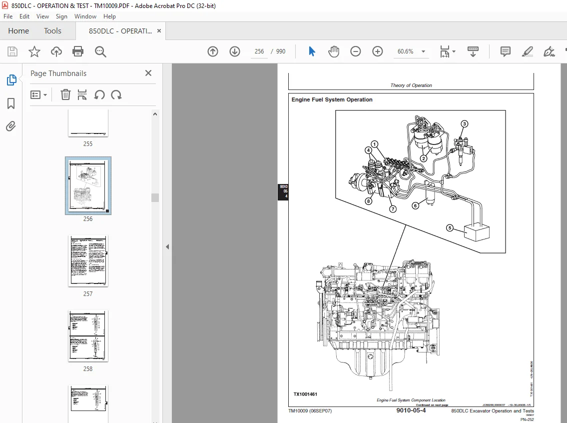
Engine Fuel System Operation256
Engine Cooling System Operation260
Engine Lubrication System Operation261
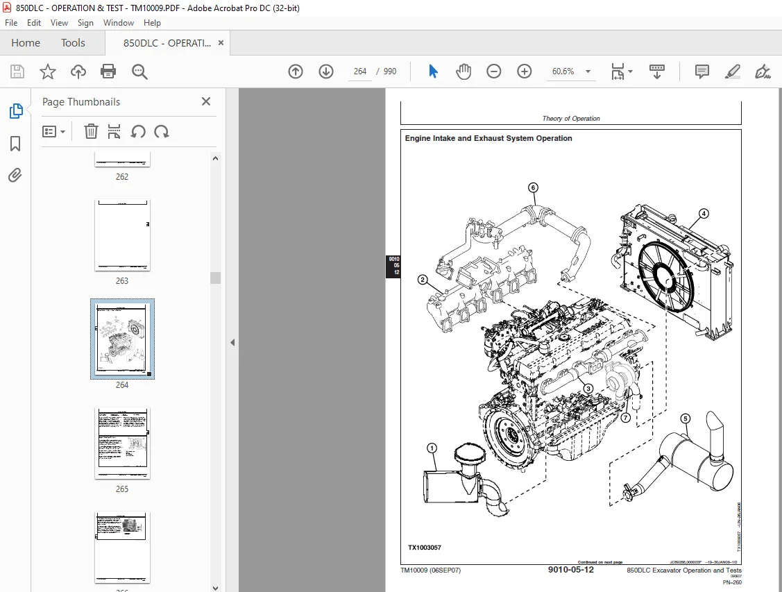
Engine Intake and Exhaust System Operation264
Engine Turbocharger Operation265
Exhaust Gas Recirculation (EGR) Operation268
Quick On Start (QOS) System Operation270
Engine Speed Control System Operation271
Diagnostic Information275
Isuzu AH-6WG1XYSA-03275
Diagnose Engine Malfunctions275
Engine Cranks But Will Not Start276
Engine Cranks But Will Not Start Diagnostic Procedure276
276
276
276
277
277
277
278
278
Engine Misfires Or Runs Irregularly279
Engine Misfires Or Runs Irregularly Diagnostic Procedure279
279
279
280
280
280
281
281
281
282
282
282
282
282
Engine Does Not Develop Full Power283
Engine Does Not Develop Full Power Diagnostic Procedure283
283
283
283
284
284
284
285
285
285
285
285
286
286
Engine Overheats286
Engine Overheats Diagnostics Procedure286
286
287
287
287
Auto-Idle Does Not Work287
Auto-Idle Does Not Work Diagnostics Procedure287
287
287
288
288
288
Coolant Temperature Too Low289
Coolant Temperature Too Low Diagnostics Procedure289
289
289
Coolant in Oil or Oil in Coolant289
Coolant in Oil or Oil in Coolant Diagnostics Procedure289
289
289
290
290
Low Engine Oil Pressure290
Low Engine Oil Pressure Diagnostics Procedure290
290
290
290
291
291
High Engine Oil Pressure291
High Engine Oil Pressure Diagnostics Procedure291
291
Engine Uses Too Much Oil291
Engine Uses Too Much Oil Diagnostics291
292
292
292
Engine Uses Too Much Fuel292
Engine Uses Too Much Fuel Diagnostic Procedure292
293
293
Engine Emits Excessive White Exhaust Smoke294
Engine Emits Excessive White Exhaust Smoke Diagnostic Procedure294
294
294
295
295
295
295
Engine Emits Excessive Black or Gray Exhaust Smoke296
Engine Emits Excessive Black or Gray Exhaust Smoke Diagnostic Procedure296
296
296
296
296
297
297
298
298
298
Turbocharger Excessively Noisy or Vibrates298
Turbocharger Excessively Noisy or Vibrates Diagnostics Procedure298
299
299
299
Oil Dripping From Turbocharger Adapter299
Oil Dripping From Turbocharger Adapter Diagnostics Procedure299
299
299
Excessive Drag in Turbocharger Rotating Members299
Excessive Drag in Turbocharger Rotating Members Diagnostics Procedure300
300
300
Fuel In Oil300
Fuel In Oil Diagnostics Procedure300
300
Tests301
Serpentine Belt Tension Check301
Check and Adjust Injection Pump Timing302
Engine Valve Lash (Clearance) Check and Adjust304
Engine Compression Pressure Test307
Air Filter Restriction Indicator Switch308
Air Intake System Leakage Test309
Engine Power Test Using Turbocharger Boost Pressure311
Engine Oil Pressure Test315
Rail Pressure Control Test316
Injector Balance Test (Injector Misfire Test)319
Injector Force Drive Test322
EGR Regulating Valve Test324
Injector ID Code Registration327
Injector ID Code Upload336
Injector ID Code Download340
Electrical System345
System Information349
Electrical Diagram Information349
System Diagrams359
Explanation of Wire Markings359
Fuse and Relay Specifications360
System Functional Schematic, Wiring Diagram, and Component Location Master Legend364
System Functional Schematic370
JDLink™ System Functional Schematic—If Equipped378
Cab Harness (W1) Component Location380
Cab Harness (W1) Wiring Diagram382
Machine Harness (W2) Component Location388
Machine Harness (W2) Wiring Diagram390
Monitor Harness (W3) Component Location396
Monitor Harness (W3) Wiring Diagram398
Engine Harness (W4) Component Location400
Engine Harness (W4) Wiring Diagram402
Engine Interface Harness (W5) Component Location404
Engine Interface Harness (W5) Wiring Diagram406
Air Conditioner Harness (W6) Component Location408
Air Conditioner Harness (W6) Wiring Diagram410
Control Valve Harness (W7) Component Location412
Control Valve Harness (W7) Wiring Diagram414
Pump Harness (W8) Component Location416
Pump Harness (W8) Wiring Diagram418
Auxiliary Fuse Box Harness (W9) Component Location420
Auxiliary Fuse Box Harness (W9) Wiring Diagram422
Cab Switch Harness (W10) Component Location423
Cab Switch Harness (W10) Wiring Diagram424
Pilot Shutoff Switch Harness (W11) Component Location425
Pilot Shutoff Switch Harness (W11) Wiring Diagram426
Heated Air Seat Harness (W12) Component Location428
Heated Air Seat Harness (W12) Wiring Diagram429
Seat Heater Switch Harness (W13) Component Location430
Seat Heater Switch Harness (W13) Wiring Diagram432
Multi-Function Pilot Control Lever Harness (W14) Component Location434
Multi-Function Pilot Control Lever Harness (W14) Wiring Diagram436
Travel Alarm Cancel Switch Harness (W15) Component Location437
Travel Alarm Cancel Switch Harness (W15) Wiring Diagram437
Reversing Fan Switch Harness (W16) Component Location438
Reversing Fan Switch Harness (W16) Wiring Diagram438
Pilot Shutoff Valve Harness (W17) Component Location439
Pilot Shutoff Valve Harness (W17) Wiring Diagram439
Oil Cooler Harness (W20) Component Location440
Oil Cooler Harness (W20) Wiring Diagram441
JDLink™ System Harnesses (W50, W51, W52, W53, and W54) Component Location—If Equipped442
Machine Information Gateway (MIG) Harness (W50) Wiring Diagram—If Equipped444
GlobalTRACS® Terminal (GTT) Harness (W51) Wiring Diagram—If Equipped446
JDLink™ CAN Harness (W52) Wiring Diagram—If Equipped448
JDLink™ Power Harness (W53) Wiring Diagram—If Equipped450
JDLink™ Jumper Harness (W54) Wiring Diagram—If Equipped452
Sub-System Diagnostics453
Controller Area Network (CAN) Theory of Operation453
Starting and Charging Circuit Theory of Operation455
Quick On System (QOS) Preheat Circuit Theory of Operation458
Monitor Circuit Theory of Operation460
Engine Control Module (ECM) Circuit Theory of Operation464
Main Controller (MCF) Circuit Theory of Operation468
Information Controller (ICF) Theory of Operation483
Travel Alarm Circuit Theory of Operation485
Windshield Wiper and Washer Circuit Theory of Operation487
Pilot Shutoff Circuit Theory of Operation490
Monitor Operation493
Monitor Menu Operation493
Monitor Service Menu Operation493
References497
Monitor Data Items497
Monitor Data Items Using the Monitor Display499
Reading Diagnostic Trouble Codes With Monitor Display501
JDLink™ Connection Procedure504
Tech 2 Diagnostic Scan Tool Connection Procedure506
Reading Diagnostic Trouble Codes With Tech 2 Diagnostic Scan Tool513
Tech 2 Data Display515
Service ADVISOR™ Diagnostic Application518
Service ADVISOR™ Connection Procedure519
Reading Diagnostic Trouble Codes With Service ADVISOR™ Diagnostic Application520
Dr ZX Diagnostic Application523
Personal Digital Assistant (PDA) Connection To Excavator Using Dr ZX Application523
Reading Diagnostic Trouble Codes With Dr ZX526
Main Controller (MCF) Diagnostics Using Dr ZX529
Engine Controller (ECM) Diagnostics Using Dr ZX546
Monitor Controller Diagnostics Using Dr ZX551
Dr ZX Password Change556
Pump Learning Procedure559
Machine Information Center (MIC) Application562
Information Controller (ICF) Initialization563
Information Controller (ICF) Model and Serial Number567
Information Controller (ICF) Date and Time571
Information Controller (ICF) Control Data: Initialize574
Information Controller (ICF) Satellite Terminal578
Information Controller (ICF) Data Download578
Information Controller (ICF) Recorded Data583
Fuse Test586
Relay Test590
Pressure Sensor Test591
Solenoid Test593
Proportional Solenoid Test594
Alternator Test595
Electrical Component Checks596
Component Checks596
Battery Remove and Install602
Rear Cover Remove and Install604
Main Controller (MCF) Remove and Install605
Engine Control Module (ECM) Remove and Install606
Information Controller (ICF) Remove and Install607
Monitor Controller Remove and Install607
Key Switch Remove and Install610
Switch Panel Remove and Install611
Travel Alarm Remove and Install612
Left Console Switch Remove and Install613
Disconnect Tab Retainer Connectors613
Disconnecting Spring Wire Clip Connectors614
Replace DEUTSCH™ Connectors614
Replace DEUTSCH™ Rectangular or Triangular Connectors615
Install DEUTSCH™ Contact616
Replace WEATHER PACK™Connector617
Install WEATHER PACK™Contact618
Replace (Pull Type) Metri-Pack™ Connectors620
Replace (Push Type) Metri-Pack™ Connectors621
Replace CINCH™ Connectors622
Install CINCH™ Contact624
Repair 32 and 48 Way CINCH™ Connectors625
Remove Connector Body from Blade Terminals628
Power Train629
Theory of Operation631
Track Adjuster and Recoil Spring Operation631
Travel Gearbox Operation632
Diagnostic Information635
Diagnose Undercarriage Components Malfunctions635
Noisy or Loose Track Chain Diagnostic Procedure635
Measure Swing Bearing Wear640
Hydraulic System643
Theory of Operation648
Hydraulic System Diagram and Operation648
Fan Drive System Diagram and Operation649
Pilot System Diagram and Operation650
Pilot Pump, Pressure Regulating Valve, and Filter Operation652
Pilot Shutoff Solenoid Valve Operation653
Pilot Control Valve Operation656
Travel Pilot Control Valve Operation658
Boom Up Shockless Valve Operation660
Pilot Signal Manifold Operation661
Pilot Operation of Control Valve Operation672
Pump 1 and 2, Fan Drive Pump, and Gearbox Operation676
Pump 1 and 2 Regulator Operation680
Fan Drive Pump Regulator Operation684
Arm 2 Flow Rate Circuit Operation694
Control Valve Operation697
Control Valve Check Valves Identification and Operation712
Main Relief and Power Digging Valve Circuit Operation716
Circuit Relief and Anticavitation Valve Operation722
Travel Flow Combiner Valve Circuit Operation724
Boom Regenerative Valve Circuit Operation727
Arm Regenerative Valve Circuit Operation729
Bucket Regenerative Valve Circuit Operation731
Boom and Arm Reduced Leakage Valves Operation733
Boom Flow Rate Circuit Operation737
Boom Mode Circuit Operation742
Counterweight Removal Circuit Operation742
Swing Gearbox Operation743
Swing Motor and Park Brake Circuit Operation744
Swing Motor Park Brake Release Circuit Operation748
Center Joint Operation749
Travel Motor and Park Brake Circuit Operation750
Travel Motor Speed Circuit Operation752
Boom, Arm, and Bucket Cylinder Operation754
Counterweight Removal Cylinder Operation755
Return Filter Operation756
Diagnostic Information757
Diagnose No Hydraulics Malfunctions757
No Hydraulic Functions Diagnostic Procedure757
S.M 6/1/25