Trusted Business
Verified & Licensed
Virus Free Files
100% Safe Downloads
Secure Payment
SSL Protected
Instant Delivery
Available Immediately
John Deere 844J Loader Repair TM2307 Technical Manual – PDF DOWNLOAD
$31.95
John Deere 844J Loader Repair TM2307 Technical Manual – PDF DOWNLOAD
Instant PDF Download
Available immediately
Save to Your Device
Download & keep forever
Antivirus Scanned
100% virus-free
Trusted Worldwide
175,000+ customers
Description
John Deere 844J Loader Repair TM2307 Technical Manual – PDF DOWNLOAD
FILE DETAILS:
John Deere 844J Loader Repair TM2307 Technical Manual – PDF DOWNLOAD
Language : English
Pages : 658
Downloadable : Yes
File Type : PDF
IMAGES PREVIEW OF THE MANUAL:
TABLE OF CONTENTS:
John Deere 844J Loader Repair TM2307 Technical Manual – PDF DOWNLOAD
Contents 3
General Information 7
Safety Information 9
Recognize Safety Information 9
Follow Safety Instructions 9
Operate Only If Qualified 10
Wear Protective Equipment 10
Avoid Unauthorized Machine Modifications 10
Add Cab Guarding For Special Uses 11
Inspect Machine 11
Stay Clear of Moving Parts 11
Avoid High-Pressure Oils 12
Beware of Exhaust Fumes 12
Prevent Fires 13
Prevent Battery Explosions 13
Handle Chemical Products Safely 14
Dispose of Waste Properly 14
Prepare for Emergencies 14
Use Steps and Handholds Correctly 15
Start Only From Operator’s Seat 15
Use and Maintain Seat Belt 15
Prevent Unintended Machine Movement 16
Avoid Work Site Hazards 17
Use Special Care When Operating Loader 18
Keep Riders Off Machine 18
Avoid Backover Accidents 19
Avoid Machine Tip Over 19
Operating on Slopes 20
Operating or Traveling On Public Roads 20
Inspect and Maintain ROPS 21
Add and Operate Attachments Safely 21
Park And Prepare For Service Safely 22
Service Cooling System Safely 22
Remove Paint Before Welding or Heating 23
Make Welding Repairs Safely 24
Drive Metal Pins Safely 24
Wheels 25
Powered Wheels And Fasteners 27
Wheel Remove and Install 27
Tire Remove and Install 28
Axles And Suspension Systems 31
Removal and Installation 33
Front Axle Remove and Install 33
Rear Axle Remove and Install 36
Axle Oscillating Supports Disassemble and Assemble 40
Oscillating Support Wear Bushing Remove and Install 44
Axle Shafts And U-Joints 48
Universal Joint and Drive Shaft Remove and Install 48
Axle Shaft, Bearings, And Reduction Gears 52
Axle Planetary Gear Case Disassemble and Assemble 52
Differential Disassemble and Assemble 83
Transmission135
Remove and Install137
Transmission Remove and Install137
Gears, Shafts, Bearings and Power Shift Clutch144
Torque Converter Input Shaft Remove and Install144
Torque Converter and Housing Disassemble and Assemble146
Transmission Drive One Remove and Install161
Transmission Drive One Disassemble and Assemble164
Transmission Drive Two Disassemble and Assemble174
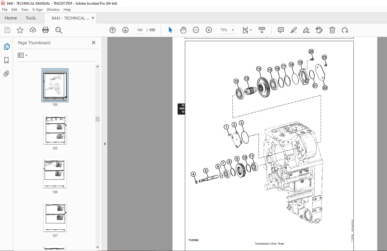
Transmission Drive Three Disassemble and Assemble180
Secondary Steering Drive Disassemble and Assemble194
Output Shaft Drive Disassemble and Assemble195
Clutch Packs Remove and Install217
Low Range Forward Clutch (KV) and First Speed Clutch (K1) Disassemble and Assemble223
High Range Forward Clutch (K4) and Third Speed Clutch (K3) Disassemble and Assemble250
Reverse Clutch (KR) and Second Speed Clutch (K2) Disassemble and Assemble275
Low Range Forward Clutch (KV) and First Speed Clutch (K1) Bearing Preload Adjustment301
High Range Forward Clutch (K4) and Third Speed Clutch (K3) Bearing Preload Adjustment306
Reverse Clutch (KR) and Second Speed Clutch (K2) Bearing Preload Adjustment310
Hydraulic System315
Transmission Oil Pump Remove and Install315
Transmission Control Valve Remove and Install318
Transmission Control Valve Disassemble and Assemble320
Transmission Suction Screen Remove and Install335
Engine337
Removal And Installation339
POWERTECH® 125 L (6125) John Deere Engines339
Engine Remove and Install339
Engine Auxiliary Systems349
Cooling System351
Charge Air Cooler Remove and Install351
Radiator Remove and Install352
Axle Oil Cooler Remove and Install355
Hydraulic Oil Cooler Remove and Install357
Transmission Oil Cooler Remove and Install360
Cooling Package Plenum Remove and Install361
External Exhaust System368
Muffler Remove and Install368
External Fuel Supply Systems372
Fuel Tank and Fuel Tank Bottom Guard Remove and Install372
Steering System377
Hydraulic System379
Orbital Steering Valve Remove and Install379
Orbital Steering Priority Valve Remove and Install381
Orbital Steering Priority Valve Disassemble and Assemble384
Joystick Steering Valve Remove and Install385
Joystick Steering Valve Disassemble and Assemble388
Steering Column Remove and Install390
Steering Cylinder Remove and Install (SN —612719)391
Steering Cylinder and Frame Bushings Remove and Instal (SN —612719)393
Steering Cylinder Remove and Install (SN 612720— )394
Steering Cylinder and Frame Bushings Remove and Install (SN 612720— )396
Steering Cylinder Disassemble and Assemble397
Secondary Steering Pump Remove and Install397
Secondary Steering Manifold Remove and Install398
Secondary Steering Manifold Disassemble and Assemble400
Loader Start-Up Procedure401
Service Brakes403
Hydraulic System405
Brake Valve Remove and Install405
Brake Accumulator Remove and Install408
Park Brake411
Active Elements413
Park Brake Remove and Install413
Park Brake Disassemble and Assemble416
Hydraulic System423
Park Brake Release Solenoid Valve Remove and Install423
Park Brake Pressure Switch Remove and Install425
Frame or Supporting Structure427
Frame Installation429
Welding Repair of Major Structure429
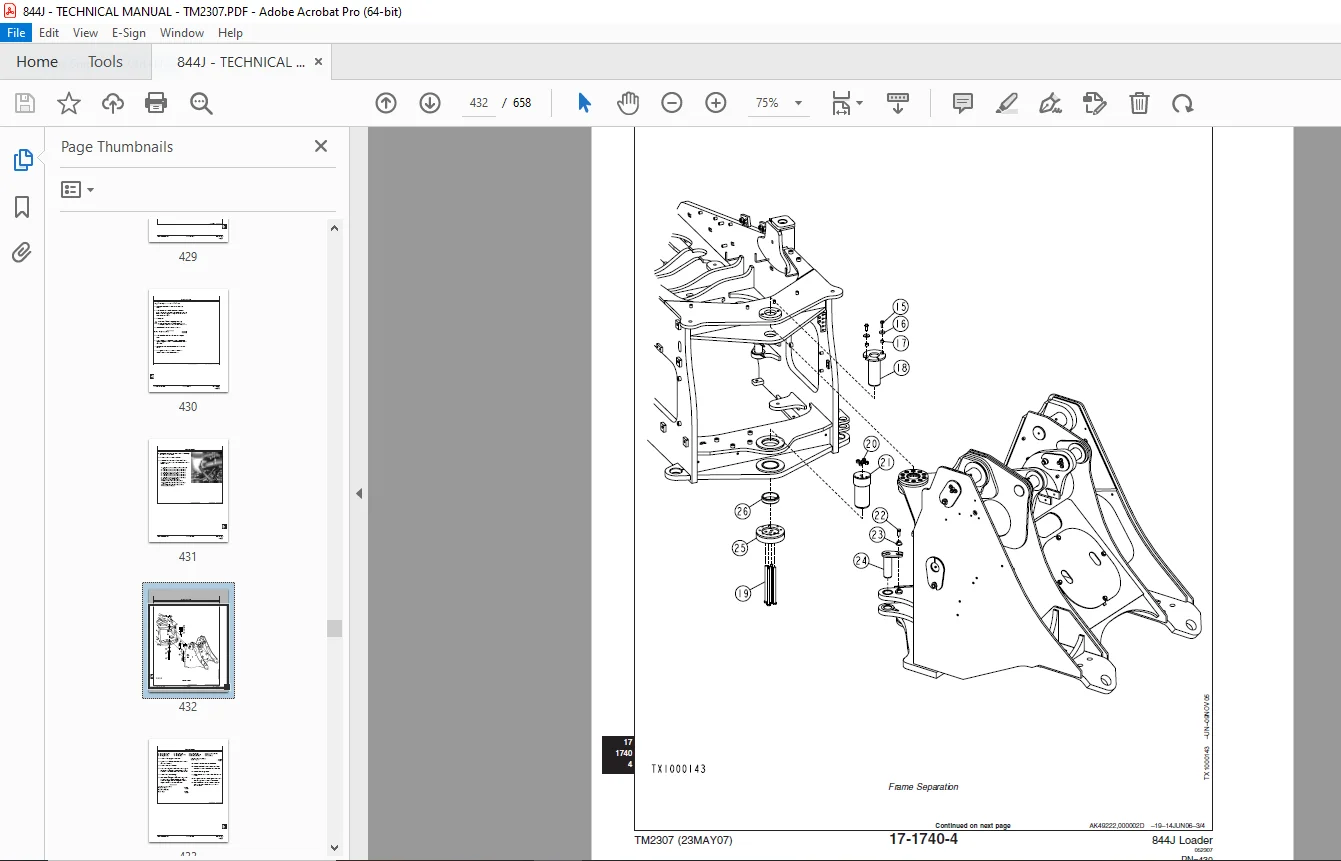
Separate Engine and Loader Frame430
Upper Pivot Bearing and Seals Remove and Install434
Lower Pivot Bearing and Seals Remove and Install436
Frame Bottom Guards439
Transmission Bottom Guard Remove and Install439
Chassis Weights442
Counterweights Remove and Install442
Operator’s Station445
Removal and Installation447
Cab Remove and Install447
Operator Enclosure453
Windowpanes Remove and Install453
Cab Door Hold-Open Release Adjust453
Front and Rear Windshield Wiper Remove and Install454
Rivet Nut Installation460
Seat and Seat Belt465
Seat Remove and Install465
Seat Belt Remove and Install466
Joystick Armrest and Wiring Harness Remove and Install468
Joystick Controller Assembly Remove and Install472
Armrest Disassemble and Assemble476
Tilt Pivot Disassemble and Assemble478
Rear Pivot Tightening482
Heating and Air Conditioning487
Air Conditioning System Fittings Reference Chart487
R134a Refrigerant Cautions and Proper Handling489
Flush and Purge Air Conditioner System491
R134a Refrigerant Oil Information494
R134a Refrigerant Recovery/Recycling and Charging Station Installation Procedure495
Recover R134a Refrigerant496
Evacuate R134a System497
Charge R134a System498
Compressor Remove and Install498
Compressor Clutch—R134a Disassemble and Assemble500
Check Clutch Hub Clearance—R134a501
Condenser Remove and Install502
Receiver/Dryer Remove and Install503
Heater and Air Conditioner Remove and Install504
Heater/Evaporator Coil Remove and Install506
Expansion Valve Remove and Install507
Freeze Control Switch Remove and Install508
Heater Control Valve Remove and Install509
Heater Control Valve Leak Check509
Main Blower Assembly Remove and Install510
Pressurizer Motor Assembly Remove and Install511
Sheet Metal and Styling513
Hood or Engine Enclosure516
Hood Remove and Install516
Rear Hood Remove and Install518
Engine Side Shields Remove and Install519
Loader521
Bucket524
Bucket Remove and Install524
Welded Bucket Cutting Edges Remove and Install528
Bolt On Bucket Cutting Edge and Bucket Guard Remove and Install529
Cracked Cutting Edge Repair531
Bucket Teeth with Segmented Cutting Edge Remove and Install532
Bucket Wear Plate Remove and Install535
Bucket Spill Guard Remove and Install538
Rock Bucket Disassemble and Assemble542
Rock Kicker Remove and Install547
Frames553
NeverGrease™ Pin Joints553
Bucket Tilt Linkage Remove and Install556
Bucket Linkage Seals and Bushings Remove and Install564
Boom Remove and Install566
Boom Bushings and Seals Remove and Install570
Hydraulic System575
Hydraulic Pump 1 Remove and Install575
Hydraulic Pump 2 Remove and Install578
Hydraulic Pump 3 Remove and Install580
Hydraulic Pump 1, 2 and 3 Disassemble and Assemble584
Loader Control Valve Remove and Install585
Loader Control Valve Disassemble and Assemble590
Auxiliary Valve Section and Bucket Valve Section Disassemble and Assemble592
Boom Valve Section Disassemble and Assemble594
System Relief Valve Disassemble and Assemble595
Circuit Relief Valve Disassemble and Assemble596
Service Auxiliary, Bucket and Boom Section Pilot Orifice Check Valve596
Boom Cylinder Remove and Install597
Bucket Cylinder Remove and Install601
Boom and Bucket Cylinder Bushings and Seals Remove and Install603
Boom or Bucket Cylinder Disassemble and Assemble604
Hydraulic System Manifold Remove and Install604
Hydraulic System Manifold Disassemble and Assemble606
Boom Down Accumulator Remove and Install607
Single Lever (Joystick) Pilot Control Valve Remove and Install610
Pilot Control Valve Disassemble and Assemble611
Two Lever (Fingertip) Pilot Control Valve Remove and Install615
Hydraulic Oil Reservoir Remove and Install617
Hydraulic Return Manifold Remove and Install619
Ride Control Remove and Install622
Ride Control Valve Disassemble and Assemble626
Pin Disconnect Valve Remove and Install628
Pin Disconnect Valve Disassemble and Assemble630
Fan Motor Remove and Install630
Fan Pump Remove and Install634
Fan Pump Disassemble and Assemble636
Fan Load Sense Manifold Remove and Install637
Fan Load Sense Manifold Disassemble and Assemble638
Reverse Fan Valve Remove and Install640
Reverse Fan Valve Disassemble and Assemble642
Dealer Fabricated Tools645
Dealer Fabricated Tools647
DFT1269 Loader Control Valve Lifting Hardware647
DF1044 Air Deflector Bushing649
DESCRIPTION:
John Deere 844J Loader Repair TM2307 Technical Manual – PDF DOWNLOAD
- Foreword :
- This manual is written for an experienced technician. Essential tools required in performing certain service work are identified in this manual and are recommended for use. Live with safety: Read the safety messages in the introduction of this manual and the cautions presented throughout the text of the manual.
- This is the safety-alert symbol. When you see this symbol on the machine or in this manual, be alert to the potential for personal injury. Technical manuals are divided in two parts: repair and operation and tests. Repair sections tell how to repair the components. Operation and tests sections help you identify the majority of routine failures quickly.
- Information is organized in groups for the various components requiring service instruction. At the beginning of each group are summary listings of all applicable essential tools, service equipment and tools, other materials needed to do the job, service parts kits, specifications, wear tolerances, and torque values.
- Technical Manuals are concise guides for specific machines. They are on-the-job guides containing only the vital information needed for diagnosis, analysis, testing, and repair. Fundamental service information is available from other sources covering basic theory of operation, fundamentals of troubleshooting, general maintenance, and basic type of failures and their causes.
G.B 07/01/2025