Trusted Business
Verified & Licensed
Virus Free Files
100% Safe Downloads
Secure Payment
SSL Protected
Instant Delivery
Available Immediately
John Deere 844J Loader Operation and Test Technical Manual TM2306 PDF
$32.95
John Deere 844J Loader Operation and Test Technical Manual TM2306 – PDF DOWNLOAD
Instant PDF Download
Available immediately
Save to Your Device
Download & keep forever
Antivirus Scanned
100% virus-free
Trusted Worldwide
175,000+ customers
Description
John Deere 844J Loader Operation and Test Technical Manual TM2306 – PDF DOWNLOAD
FILE DETAILS:
John Deere 844J Loader Operation and Test Technical Manual TM2306 – PDF DOWNLOAD
Language : English
Pages : 716
Downloadable : Yes
File Type : PDF
IMAGES PREVIEW OF THE MANUAL:
TABLE OF CONTENTS:
John Deere 844J Loader Operation and Test Technical Manual TM2306 – PDF DOWNLOAD
Contents 3
General Information 5
Safety Information 7
Recognize Safety Information 7
Follow Safety Instructions 7
Operate Only If Qualified 8
Wear Protective Equipment 8
Avoid Unauthorized Machine Modifications 8
Add Cab Guarding For Special Uses 9
Inspect Machine 9
Stay Clear of Moving Parts 9
Avoid High-Pressure Oils 10
Beware of Exhaust Fumes 10
Prevent Fires 11
Prevent Battery Explosions 11
Handle Chemical Products Safely 12
Dispose of Waste Properly 12
Prepare for Emergencies 12
Use Steps and Handholds Correctly 13
Start Only From Operator’s Seat 13
Use and Maintain Seat Belt 13
Prevent Unintended Machine Movement 14
Avoid Work Site Hazards 15
Use Special Care When Operating Loader 16
Keep Riders Off Machine 16
Avoid Backover Accidents 17
Avoid Machine Tip Over 17
Operating on Slopes 18
Operating or Traveling On Public Roads 18
Inspect and Maintain ROPS 19
Add and Operate Attachments Safely 19
Park And Prepare For Service Safely 20
Service Cooling System Safely 20
Remove Paint Before Welding or Heating 21
Make Welding Repairs Safely 22
Drive Metal Pins Safely 22
Operational Checkout Procedure 23
Operational Checkout Procedure 25
Operational Checkout Procedure 25
Key Switch OFF, Engine OFF Checks 25
26
Key Switch ON, Engine OFF Checks 26
Engine 45
Theory Of Operation 47
POWERTECH® 125L (6125) John Deere Engines 47
Fast Fill Fuel System Theory of Operation 48
Wait to Start / Start Inhibit Theory of Operation 49
Engine Air Heater Theory of Operation 50
Pilot Injection Theory Of Operation 51
Diagnostic Information 53
POWERTECH® 125L (6125) John Deere Engines 53
Diagnose Observable Machine Symptoms—Level 6 Electronic Fuel Systems With Lucas EUIs 54
Diagnose Fast Fill System Malfunctions 55
Cooling System Component Location 56
Fuel System Component Location 58
Tests 61
Engine Speed Test 61
Intake Manifold Pressure Test—Turbocharger Boost 62
Electrical System 65
System Information 68
Electrical Diagram Information 68
System Diagrams 76
Fuse and Relay Specifications 76
System Functional Schematic, Wiring Diagram and Component Location Master Legend 78
System Functional Schematic 85
JDLink™ System Functional Schematic (SN 616018— )100
Loader Frame Harness (W2) Component Location102
Loader Frame Harness (W2) Wiring Diagram104
Load Center Harness (W3) Component Location106
Load Center Harness (W3) Wiring Diagram110
Front Console Harness (W4) Component Location124
Front Console Harness (W4) Wiring Diagram126
Engine Frame Harness (W5) Component Location128
Engine Frame Harness (W5) Wiring Diagram132
Engine Harness (W6) Component Location136
Engine Harness (W6) Wiring Diagram138
Engine Air Heater Harness (W7) Component Location142
Engine Air Heater Harness (W7) Wiring Diagram144
Joystick Steering Harness (W8) Component Location146
Joystick Steering Harness (W8) Wiring Diagram148
Transmission Harness (W10) Component Location150
Transmission Harness (W10) Wiring Diagram152
Rear Frame Harness (W13) Component Location154
Rear Frame Harness (W13) Wiring Diagram156
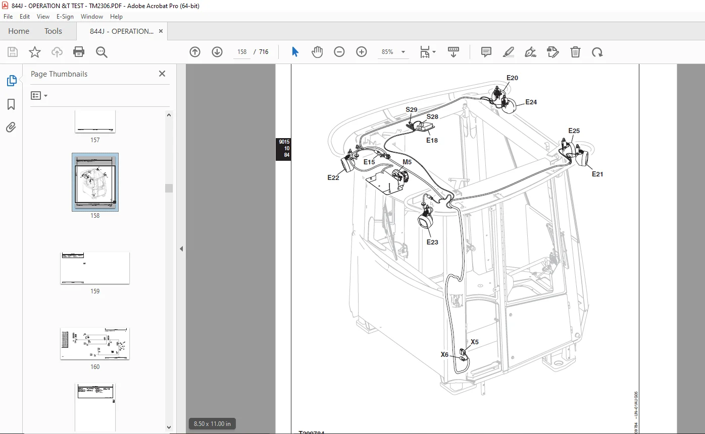
Cab Roof Harness (W19) Component Location158
Cab Roof Harness (W19) Wiring Diagram160
Blower and A/C Harness (W20) Component Location162
Blower and A/C Harness (W20) Wiring Diagram164
JDLink™ System Harnesses (W29, and W30) Component Location (S N 616018— )166
GlobalTRACS® Terminal (GTT) Harness (W29) Wiring Diagram (SN 616018— )168
Machine Information Gateway (MIG) Harness (W30) Wiring Diagram (SN 616018— )170
Radio Harness (W34) Component Location172
Radio Harness (W34) Wiring Diagram174
Sub-System Diagnostics177
Starting and Charging Circuit Theory of Operation177
Controller Area Network (CAN) Theory of Operation179
Engine Control Unit (ECU) Circuit Theory of Operation181
Flex Load Controller (FLC) Circuit Theory of Operation184
Transmission Control Unit (TCU) Circuit Theory of Operation205
CAN Monitor Unit (CMU) Circuit Theory of Operation212
References239
Diagnostic Trouble Code Quick Reference239
CAN Monitor Unit (CMU) Diagnostic Trouble Codes244
Flex Load Controller (FLC) Diagnostic Trouble Codes248
Sealed Switch Module (SSM) Diagnostic Trouble Codes273
Transmission Control Unit (TCU) Diagnostic Trouble Codes279
Engine Control Unit (ECU) Diagnostic Trouble Codes299
Joystick Steering Valve (JSV) Diagnostic Trouble Codes306
Joystick Steering Controller (JSC) Diagnostic Trouble Codes311
Flex Load Controller (FLC) Fault Exceptions312
JDLink™ Connection Procedure (SN 616018— )316
Alternator Test317
Transmission Control Unit (TCU) Calibration319
CAN Circuit Testing321
Controller Area Network (CAN) Diagnostics 321
322
322
323
324
325
325
326
Electrical Component Specifications327
Transmission Control Valve Solenoid Check334
Clutch Cut-Off Sensor Check and Adjustment336
Boom Height Kickout and Return-to-Carry Adjustment337
Return-To-Dig Adjustment338
Sensor Circuitry Check339
Transmission Speed Sensor Adjustment341
Change Back-Up Alarm Volume343
Remove and Install Pressure Switches344
Reprogram CAN Monitor Unit (CMU)345
Machine Option Reconfiguration347
Replace (Push Type) METRI-PACK™ Connectors350
Replace (Pull Type) METRI-PACK™ Connectors351
Install METRI-PACK™ Contact352
Replace DEUTSCH™ Connectors353
Install DEUTSCH™ Contact354
Replace WEATHER PACK™ Connector356
Install WEATHER PACK™ Contact357
Replace CINCH™ Connectors358
Install CINCH™ Contact360
Repair 32 and 48 Way CINCH™ Connectors361
Remove Connector Body from Blade Terminals364
Power Train365
Theory Of Operation367
Power Train System Operation367
Transmission Operation368
Transmission Operation—First Gear Forward370
Torque Converter Operation372
Transmission Clutch Engagement and Solenoids Activated373
Clutch Pack Operation374
Transmission Clutch Modulation375
Transmission Hydraulic System376
Transmission Pump Operation377
Transmission Control Valve Components378
Thermal Bypass Valve Operation382
Differential Operation—Conventional384
Differential Operation—Limited Slip386
Axle Planetary Gearcase, Service Brake and Axle Cooling Operation388
Park Brake Operation390
Diagnostic Information393
Diagnose Transmission Malfunctions393
Diagnose Differential and Axle Malfunctions407
Diagnose Service Brake Malfunctions413
Diagnose Drive Line Malfunctions416
Diagnose Park Brake Malfunctions417
Transmission System Schematic—First Forward420
Transmission Component Location422
Power Train Component Location424
Adjustments427
External Service Brake Inspection427
Service Brake Bleeding Procedure429
Tests431
Transmission Oil Warm-Up Procedure431
Park Brake Pressure Test432
Park Brake Drag Test434
Transmission Pump Flow Test436
Transmission System Pressure Test438
Transmission Clutch Pressure Test440
Transmission Element Leakage Test443
Lube Pressure Test445
Torque Converter Stall and Engine Pulldown Test448
Torque Converter—In Pressure Test449
Torque Converter—Out Pressure Test451
Torque Converter Relief Pressure Test453
Torque Converter—Out Flow Test455
Transmission Oil Cooler Thermal Bypass Valve Temperature Test458
Transmission Oil Cooler Thermal Bypass Valve Pressure Test462
Transmission Oil Cooler Restriction Test464
Axle Circulation Pump Temperature and Flow Test466
Hydraulic System469
Theory Of Operation471
Hydraulic System Overview471
Hydraulic Pump Operation474
Hydraulic System Manifold Operation480
Steering Hydraulic System484
Orbital Steering Valve Operation485
Orbital Steering Priority Valve Operation487
Orbital Steering Operation489
Joystick Steering Valve491
Joystick Steering Operation494
Secondary Steering Operation496
Loader Hydraulic System500
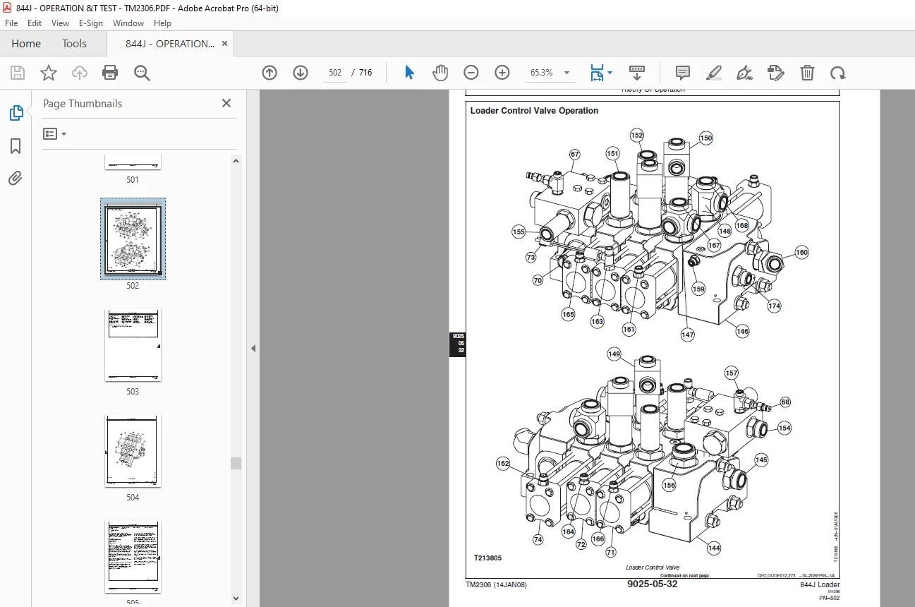
Loader Control Valve Operation502
Boom Section Operation506
Loader Control Valve—Load Sense Circuit508
Anticavitation Valve Operation509
Pilot Control Lever Operation512
Pilot Orifice Check Valve For Control Valve Sections514
Service Brake Hydraulic System516
Service Brake Valve518
Service Brake Accumulator520
Fan Pump Operation521
Fan Operation523
Hydraulic Return System528
Return Filter Operation530
Ride Control Operation531
Pin Disconnect Operation536
Diagnostic Information540
Hydraulic System Schematic—Neutral (SN —612883)540
Hydraulic System Schematic—Neutral (SN 612884— )542
Hydraulic System Component Locations544
Diagnose Hydraulic System Malfunctions556
Adjustments569
Return-To-Dig Adjustment569
Return-To-Carry and Boom Height Kickout Adjustment569
Pilot Controller Adjustment—Two Lever Pilot569
Ride Control Accumulator Pressure Discharge570
Charge Ride Control Accumulator573
Tests577
Hydraulic Oil Warm-Up Procedure577
Discharge Hydraulic System Pressure and Accumulators578
Digital Pressure And Temperature Analyzer Installation580
Pump 1 – Pump Displacement Control Valve Test581
Pump 2 / Pump 3—Pump Displacement Control Valve Test585
Pump 2 and Pump 3 Maximum Operating Pressure Test592
Hydraulic Pump 1 Flow Test596
Hydraulic Pump Flow Test—Pump 2 and Pump 3599
Hydraulic Pump Case Drain Test—Pump 1 / Pump 2 / Pump 3602
Loader System Relief Valve And Circuit Relief Valve Pressure Tests604
Pressure Reducing Valve (Pilot Pressure) Test610
Loader Cylinder Drift Test612
Boom And Bucket Cylinder Leakage Test614
Service Brake Valve Pressure Test615
Service Brake Valve Leakage Test619
Service Brake Accumulator Precharge Test623
Service Brake Accumulator Inlet Check Valve Leakage Test625
Boom Down Accumulator Precharge Test626
Pilot Control Valve Pressure Test—Two Lever (Fingertip)628
Pilot Control Valve Pressure Test—Single Lever633
Priority Valve Performance Test637
Orbital Steering Valve Leakage Test639
Orbital Steering Valve Drift Test641
Orbital Steering Cycle Time Test644
Orbital Steering Priority Valve Port LS Flow Test645
Joystick Steering Valve Pressure Test646
Joystick / Orbital Steering Priority Test648
Joystick Steering Circuit Relief Valve Test650
Joystick Steering Cycle Time Test651
Secondary Steering Manifold Leakage Test652
Secondary Steering Function Valve Test654
Secondary Steering Pressure Relief Valve Test656
Fan Pump Displacement Control Valve Test658
Fan Pump Flow Test664
Fan Pump Case Drain Test667
Fan Motor RPM Test670
Hydraulic Oil Cooler Restriction Test671
Pin Disconnect Pressure Test673
Hydraulic Oil Filter Inspection Procedure675
Heating And Air Conditioning System677
Theory Of Operation679
Air Conditioning System Cycle Of Operation679
Diagnostic Information681
Diagnose Air Conditioning System Malfunctions681
Diagnose Heater System Malfunctions684
Air Conditioner and Heater System Component Location686
Tests689
Refrigerant Cautions and Proper Handling689
Air Conditioner and Heater Operational Checks690
Visual Inspection Of Components690
690
691
691
691
691
692
692
692
Refrigerant Leak Test692
Air Conditioner Compressor Clutch Test693
Air Conditioner High/Low Pressure Switch Test694
Air Conditioner Freeze Control Switch Test696
R134a Air Conditioning System Test697
Operating Pressure Diagnostic Chart700
Dealer Fabricated Tools703
Dealer Fabricated Tools705
DFT1241—Service Brake Inspection Tool705
DESCRIPTION:
John Deere 844J Loader Operation and Test Technical Manual TM2306 – PDF DOWNLOAD
- Foreword:
- This manual is written for an experienced technician. Essential tools required in performing certain service work are identified in this manual and are recommended for use.
- Live with safety: Read the safety messages in the introduction of this manual and the cautions presented throughout the text of the manual.
- This is the safety-alert symbol. When you see this symbol on the machine or in this manual, be alert to the potential for personal injury.
- Technical manuals are divided in two parts: repair and operation and tests. Repair sections tell how to repair the components. Operation and tests sections help you identify the majority of routine failures quickly.
- Information is organized in groups for the various components requiring service instruction. At the beginning of each group are summary listings of all applicable essential tools, service equipment and tools, other materials needed to do the job, service parts kits, specifications, wear tolerances, and torque values.
- Technical Manuals are concise guides for specific machines. They are on-the-job guides containing only the vital information needed for diagnosis, analysis, testing, and repair.
- Fundamental service information is available from other sources covering basic theory of operation, fundamentals of troubleshooting, general maintenance, and basic type of failures and their causes.
G.B 06/01/25