John Deere 750J, 850J Crawler Dozers Repair Manual 10FEB06 – PDF DOWNLOAD
$28.95
John Deere 750J, 850J Crawler Dozers Repair Manual 10FEB06 – PDF DOWNLOAD
Description
John Deere 750J, 850J Crawler Dozers Repair Manual 10FEB06 – PDF DOWNLOAD
FILE DETAILS:
John Deere 750J, 850J Crawler Dozers Repair Manual 10FEB06 – PDF DOWNLOAD
Language : English
Pages :498
Downloadable : Yes
File Type : PDF
IMAGES PREVIEW OF THE MANUAL:
DESCRIPTION:
John Deere 750J 850J Crawler Dozers Repair Manual 10FEB06 – PDF DOWNLOAD
Introduction
Foreword
- This manual is written for an experienced technician. Essential tools required in performing certain service work are identified in this manual and are recommended for use. Live with safety: Read the safety messages in the introduction of this manual and the cautions presented throughout the text of the manual.
- This is the safety-alert symbol. When you see this symbol on the machine or in this manual, be alert to the potential for personal injury. Technical manuals are divided in two parts: repair and operation and tests. Repair sections tell how to repair the components.
- Operation and tests sections help you identify the majority of routine problems quickly. Information is organized in groups for the various components requiring service instruction. At the beginning of each group are summary listings of all applicable essential tools, service equipment and tools, other materials needed to do the job, service parts kits, specifications, wear tolerances, and torque values.
- Technical Manuals are concise guides for specific machines. They are on-the-job guides containing only the vital information needed for diagnosis, analysis, testing, and repair. Fundamental service information is available from other sources covering basic theory of operation, fundamentals of troubleshooting, general maintenance, and basic type of problems and their causes.
TABLE OF CONTENTS:
John Deere 750J, 850J Crawler Dozers Repair Manual 10FEB06 – PDF DOWNLOAD
Contents 5
General Information 9
Safety 11
Recognize Safety Information 11
Follow Safety Instructions 11
Operate Only If Qualified 12
Wear Protective Equipment 12
Avoid Unauthorized Machine Modifications 12
Inspect Machine 13
Stay Clear Of Moving Parts 13
Avoid High-Pressure Fluids 13
Beware Of Exhaust Fumes 14
Prevent Fires 14
Prevent Battery Explosions 14
Handle Chemical Products Safely 15
Dispose Of Waste Properly 15
Prepare For Emergencies 15
Add Cab Guarding For Special Uses 16
Use Steps And Handholds Correctly 16
Start Only From Operator’s Seat 16
Use And Maintain Seat Belt 17
Prevent Unintended Machine Movement 17
Avoid Work Site Hazards 18
Keep Riders Off Machine 18
Avoid Backover Accidents 19
Avoid Machine Tip Over 19
Add And Operate Attachments Safely 20
Park And Prepare For Service Safely 20
Service Cooling System Safely 21
Remove Paint Before Welding or Heating 21
Make Welding Repairs Safely 22
Drive Metal Pins Safely 22
Torque Values 23
Torque Value 23
Metric Bolt and Cap Screw 23
Additional Metric Cap Screw Torque Values 24
Torque Value 26
Unified Inch Bolt and Cap Screw 26
Service Recommendations for 37° Flare and 30° Cone Seat Connectors 27
Service Recommendations for O-Ring Boss Fittings 28
Service Recommendation 30
O-Ring Boss Fittings In Aluminum Housing—Excavators 30
Service Recommendations For Flared Connections—Straight or Tapered Threads 32
Service Recommendations For Flat Face O-Ring Seal Fittings 33
Service Recommendation 34
O-Ring Face Seal Fittings with SAE Inch Hex Nut and Stud End for High Pressure 34
O-Ring Face Seal Fittings with Metric Hex Nut and Stud End for Standard Pressure 36
O-Ring Face Seal Fittings with Metric Hex Nut and Stud End for High Pressure 38
Service Recommendations for Metric Series Four Bolt Flange Fitting 40
Service Recommendations For Inch Series Four Bolt Flange Fittings 41
Service Recommendation 42
Inch Series Four Bolt Flange For High Pressure 42
Service Recommendations For Non-Restricted Banjo (Adjustable) Fittings 43
Service Recommendations For O-Ring Boss Fittings With Shoulder 45
Service Recommendation 48
Metric 24° O-Ring Seal DIN 20078 48
Tracks 51
Track System 53
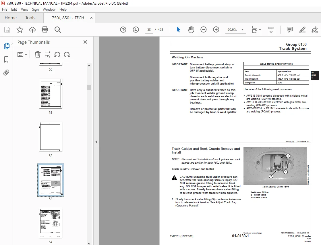
Welding On Machine 53
Track Guides and Rock Guards Remove and Install 53
Carrier Roller Wear Inspection 57
Carrier Roller Remove and Install 57
Carrier Roller Disassemble and Assemble 59
Metal Face Seals Inspection 62
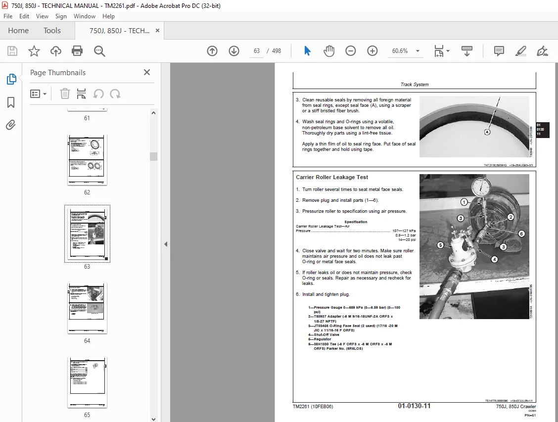
Carrier Roller Leakage Test 63
Track Roller Wear Inspection 64
Track Roller Remove and Install 66
Track Roller Disassemble and Assemble 68
Track Roller Leakage Test 78
Track Shoe Grouser Wear Inspection 79
Track Shoe Remove and Install 80
Pivot Shaft Remove and Install 82
Crossbar Remove and Install 82
Crossbar Disassemble and Assemble 88
Track Link Height Inspection 89
Bushing Outside Diameter for Lubricated Track Chain Inspection 90
Track Pitch for Lubricated Track Chain Inspection 92
Lubricated Track Chain Remove and Install 93
Lubricated Track Chain to Turn Bushings and Lubricate Chain Disassemble 97
Lubricated Track Chain to Turn Bushings and Lubricate Chain Assemble100
Lubricated Track Chain to Turn Pins and Bushings and Not Lubricate Disassemble and Assemble107
Track Sag Adjustment114
Track Adjuster Cylinder and Recoil Spring Remove and Install116
Track Adjuster Recoil Spring Disassemble and Assemble117
Track Adjuster Cylinder Disassemble and Assemble127
Track Frame Remove and Install129
Front Idler Wear Inspection137
Front Idler Remove and Install137
Front Idler Disassemble and Assemble145
Front Idler Vertical Movement Adjustment154
Front Idler Oil Leakage Test156
Sprocket Segment Remove and Install157
Axles and Suspension Systems159
Drive Axle Housing and Support161
Final Drive Remove and Install161
Axle Shaft, Bearings and Reduction Gears169
Planet Carrier Remove and Install169
Planet Carrier Disassemble and Assemble172
Ring Gear and Hub Remove and Install175
Ring Gear and Hub Disassemble and Assemble179
Planet Housing Remove and Install180
Planet Housing Disassemble and Assemble182
Inner Final Drive Housing Remove and Install185
Inner Final Drive Housing Disassemble and Assemble188
Transmission193
Remove and Install195
Hydrostatic Pump Remove and Install195
Hydrostatic Motor Remove and Install202
Control Linkage205
Transmission Control Lever (TCL) Remove and Install205
Transmission Control Lever (TCL) Disassemble and Assemble206
Hydrostatic System226
Hydrostatic Pump Disassemble226
Charge Pump Disassemble and Assemble233
Pump Displacement Control Valve (PDCV) Disassemble and Assemble238
Multi-Function Valve Remove and Install239
Multi-Function Valve Disassemble and Assemble240
Hydrostatic Pump Assemble241
Hydrostatic Motor Disassemble251
Hydrostatic Motor Assemble256
Hydraulic Integrated Circuit (HIC) Valve Remove and Install268
Hydraulic Integrated Circuit (HIC) Valve Disassemble and Assemble270
Hydrostatic Reservoir Remove and Install272
Hydraulic Fan Motor Remove and Install275
Hydraulic Fan Pump Remove and Install279
Hydraulic Fan Reversing Valve Remove and Install280
Hydraulic Fan Reversing Valve Disassemble and Assemble282
Engine283
Removal and Installation285
Engine Remove and Install285
Oil Pan Remove and Install295
Flywheel Remove and Install297
Engine Mounts Remove and Install300
Engine Auxiliary Systems303
Cold Weather Starting Aid305
Starting Aid Assembly Remove and Install305
Cooling System307
Guards, Shroud and Fan Remove and Install307
Cooling Package Remove and Install310
Engine Speed Control315
Decelerator/Brake Pedal Remove and Install315
Decelerator/Brake Pedal Disassemble and Assemble316
External Exhaust Systems321
Muffler Remove and Install321
External Fuel Supply Systems323
Fuel Tank Remove and Install323
Dampener Drive327
Elements329
Dampener Drive Remove and Install329
Park Brake333
Park Brake335
Park Brake Remove and Install335
Control Linkage338
Park Lock Linkage Remove and Install338
Park Lock Linkage Disassemble and Assemble339
Hydraulic System343
Park Brake Disassemble and Assemble343
Equipment Attaching353
Drawbar356
Extended Rigid Drawbar Remove and Install356
Rigid Drawbar Remove and Install358
Ripper362
Ripper Remove and Install362
Frames, Chassis, or Supporting Structure365
Frame Installation367
Welding Repair of Major Structures367
Frame Bottom Guards369
Bottom Guards Remove and Install369
Chassis Weights372
Front Counterweight Remove and Install372
Rear Counterweight Remove and Install374
Operator’s Station377
Removal and Installation379
Cab/ROPS Remove and Install379
Operator Enclosure383
Remove and Install Window383
Remove and Install Windowpanes384
Hand Pump Bleed Procedure385
Seat and Seat Belt387
Disassemble and Assemble Seat387
Heating and Air Conditioning393
R134a Refrigerant Cautions393
R134a Compressor Oil Charge Check393
R134a Compressor Oil Removal394
R134a Component Oil Charge395
Leakage Testing396
R134a Refrigerant Recovery, Recycling and Charging Station Installation Procedure397
Recover R134a System398
Evacuate R134a System399
Charge R134a System401
Air Conditioner System Cleaning Procedures402
Purge R134a System403
Flush R134a System404
Evaporator or Heater Core Remove and Install406
Expansion Valve Remove and Install409
A/C Freeze Switch Remove and Install410
Upper Cab Heater Blower Motor and Heater Blower Resistor Remove and Install410
Cab Upper Heater Disassemble and Assemble412
Cab or ROPS Under Seat Heater Disassemble and Assemble414
Receiver-Dryer Remove and Install416
Condenser Remove and Install417
Compressor Remove and Install418
Compressor Clutch Disassemble and Assemble420
Clutch Hub Clearance Check422
Compressor Manifold Inspect423
Compressor Disassemble and Assemble424
Sheet Metal427
Hood and Engine Enclosures430
Hood Remove and Install430
Engine Side Shields Remove and Install432
Hood Support Remove and Install433
Safety, Convenience and Miscellaneous435
Horn and Warning Devices437
Remove and Install Reverse Alarm437
Adjust Reverse Warning Alarm Volume437
Bulldozer439
Blade441
Cutting Edges and End Bits Remove and Install441
Blade Remove and Install442
Frames448
Outside Dozer Push Beams Remove and Install448
C-Frame Remove and Install449
Hydraulic System453
Hydraulic Pump Remove and Install453
Hydraulic Pump Disassemble and Assemble455
Hydraulic Pump Control Valve Disassemble and Assemble456
Hydraulic Reservoir Remove and Install457
Hydraulic Reservoir Cleanout Cover Remove and Install461
Hydraulic Control Valve Remove and Install465
Hydraulic Control Valve Disassemble and Assemble466
Pilot Control Valve Remove and Install469
Pilot Control Valve Disassemble and Assemble 471
Quick-Drop Valve Remove and Install473
Power Angle Tilt (PAT) Cylinder Remove and Install474
Angle Cylinder (PAT) Remove and Install474
Hydraulic Cylinder Repair475
Dealer Fabricated Tools477
Dealer Fabricated Tools479
DF1065 Final Drive and Pump Adapter Bracket479
DFT1041 Track Nut Removal Tool480
DFT1063 Final Drive Lift Bracket481
DFT1132 Hydrostatic Motor Removal and Installation Tool482
DFT1137 Hydrostatic Motor Removal and Installation Tool483
DFT1167 Final Drive Lifting Bracket Adapter Spacer484
DFT1243 Lifting Bracket Extension485
DFT1250 Lifting Bracket486
DFT1260 Final Drive Lifting Fixture488
DFT1261 Rolling Torque Measurement Tool489
Page Numbers 5
Section 00 9
Group 01 11
S.M 4/1/25