
John Deere 650DLC Excavator Repair TECHNICAL MANUAL TM10010 – PDF DOWNLOAD
$30.95
John Deere 650DLC Excavator Repair TECHNICAL MANUAL TM10010 – PDF DOWNLOAD
Description
John Deere 650DLC Excavator Repair TECHNICAL MANUAL TM10010 – PDF DOWNLOAD
FILE DETAILS:
John Deere 650DLC Excavator Repair TECHNICAL MANUAL TM10010 – PDF DOWNLOAD
Language : English
Pages :528
Downloadable : Yes
File Type : PDF
IMAGES PREVIEW OF THE MANUAL:
DESCRIPTION:
John Deere 650DLC Excavator Repair TECHNICAL MANUAL TM10010 – PDF DOWNLOAD
Foreword
- This manual is written for an experienced technician. Essential tools required in performing certain service work are identified in this manual and are recommended for use. Live with safety: Read the safety messages in the introduction of this manual and the cautions presented throughout the text of the manual.
- This is the safety-alert symbol. When you see this symbol on the machine or in this manual, be alert to the potential for personal injury. Technical manuals are divided in two parts: repair and operation and tests. Repair sections tell how to repair the components. Operation and tests sections help you identify the majority of routine failures quickly.
- Information is organized in groups for the various components requiring service instruction. At the beginning of each group are summary listings of all applicable essential tools, service equipment and tools, other materials needed to do the job, service parts kits, specifications, wear tolerances, and torque values.
- Technical Manuals are concise guides for specific machines. They are on-the-job guides containing only the vital information needed for diagnosis, analysis, testing, and repair. Fundamental service information is available from other sources covering basic theory of operation, fundamentals of troubleshooting, general maintenance, and basic type of failures and their causes.
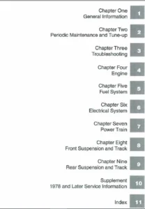
TABLE OF CONTENTS:
John Deere 650DLC Excavator Repair TECHNICAL MANUAL TM10010 – PDF DOWNLOAD
Contents 5
General Information 7
Safety 9
Recognize Safety Information 9
Follow Safety Instructions 9
Operate Only If Qualified 9
Wear Protective Equipment 10
Avoid Unauthorized Machine Modifications 10
Add Cab Guarding for Special Uses 10
Inspect Machine 10
Stay Clear of Moving Parts 11
Avoid High-Pressure Oils 11
Beware of Exhaust Fumes 11
Prevent Fires 12
Prevent Battery Explosions 12
Handle Chemical Products Safely 12
Dispose of Waste Properly 13
Prepare for Emergencies 13
Use Steps and Handholds Correctly 13
Start Only From Operator’s Seat 13
Use and Maintain Seat Belt 14
Prevent Unintended Machine Movement 14
Avoid Work Site Hazards 14
Keep Riders Off Machine 15
Avoid Backover Accidents 15
Avoid Machine Tip Over 16
Use Special Care When Lifting Objects 16
Add and Operate Attachments Safely 16
Park and Prepare for Service Safely 17
Service Cooling System Safely 17
Remove Paint Before Welding or Heating 17
Make Welding Repairs Safely 18
Drive Metal Pins Safely 18
Torque Values 19
Metric Bolt and Cap Screw Torque Values 19
Additional Metric Cap Screw Torque Values 20
Unified Inch Bolt and Cap Screw Torque Values 21
Service Recommendations for 37° Flare and 30° Cone Seat Connecto 22
Service Recommendations for O-Ring Boss Fittings 22
O-Ring Boss Fittings In Aluminum Housing Service Recommendations 24
Service Recommendations For Flared Connections—Straight or Taper 25
Service Recommendations For Flat Face O-Ring Seal Fittings 26
O-Ring Face Seal Fittings With SAE Inch Hex Nut And Stud End For 27
O-Ring Face Seal Fittings With Metric Hex Nut And Stud End For S 29
O-Ring Face Seal Fittings With Metric Hex Nut And Stud End For H 31
Service Recommendations for Metric Series Four Bolt Flange Fitti 33
Service Recommendations For Inch Series Four Bolt Flange Fitting 34
Inch Series Four Bolt Flange Fitting For High Pressure Service R 35
Tracks 37
Track System 39
Track Roller Remove and Install 39
Track Roller Disassemble and Assemble 40
Track Roller Pressure Test 45
Track Carrier Roller Remove and Install 45
Track Carrier Roller Disassemble and Assemble 47
Metal Face Seal Inspection 48
Track Shoe Remove and Install 49
Track Chain Remove and Install 50
Track Chain Disassemble and Assemble 53
Track Chain Repair to Replace Broken Part 54
Sprocket Remove and Install 56
Front Idler Remove and Install 56
Front Idler Disassemble and Assemble 57
Front Idler Pressure Test 62
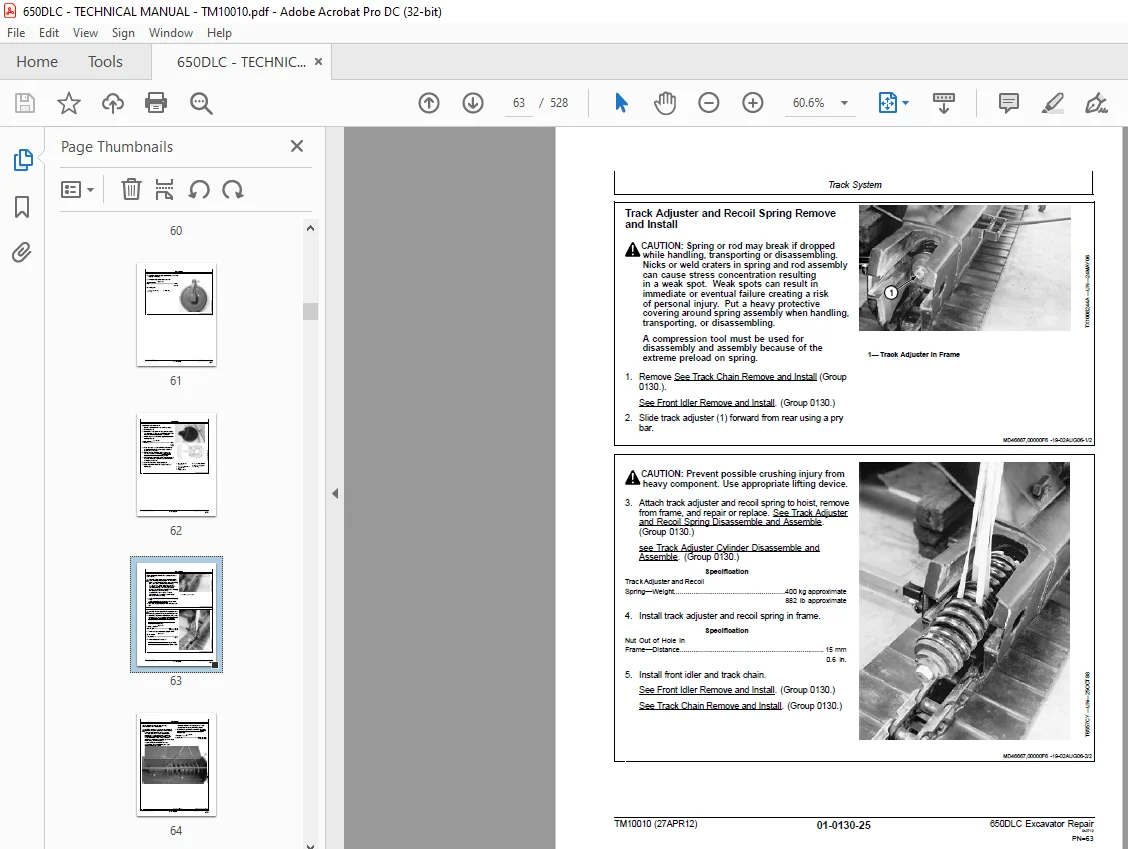
Track Adjuster and Recoil Spring Remove and Install 63
Track Adjuster and Recoil Spring Disassemble and Assemble 64
Track Adjuster Cylinder Disassemble and Assemble 66
Axles, Differentials and Suspension Systems 67
Axle Shaft, Bearings, and Reduction Gears 69
Travel Gearbox Remove and Install 69
Travel Gearbox Disassemble and Assemble 71
Hydraulic System 83
Travel Motor and Park Brake Remove and Install 83
Travel Motor and Park Brake Disassemble and Assemble 86
Counterbalance Valve Remove and Install 91
Crossover Relief Valves Remove and Install 91
Make-Up Check Valve Remove and Install 91
Travel Speed Selector Valve Remove and Install 91
Travel Motor and Park Brake Start-Up Procedure 92
Engine 93
Removal and Installation 95
Engine Remove and Install 95
Turbocharger Remove and Install 98
Turbocharger Disassemble and Assemble100
Turbocharger Inspection106
Exhaust Manifold Remove and Install110
Upper Valve Cover Remove and Install111
Lower Valve Cover Remove and Install111
Rocker Arm Shaft Assembly Remove and Install112
Rocker Arm Shaft Assembly Disassemble and Assemble113
Rocker Arm Shaft Assembly Inspection113
Intake Manifold Remove and Install116
Lead Valve Remove and Install118
Water Pump Remove and Install119
Water Pump Disassemble and Assemble120
Cylinder Head Remove and Install122
Cylinder Head Disassemble and Assemble125
Cylinder Head Inspection133
Timing Gear Case Remove and Install138
Cylinder Block Disassemble and Assemble143
Cylinder Block Inspection144
Camshaft Remove and Install145
Camshaft Inspection146
Flywheel Remove and Install148
Flywheel Disassemble and Assemble149
Flywheel Housing Remove and Install150
Oil Pan Remove and Install152
Crankshaft Remove and Install153
Crankshaft Inspection156
Piston and Connecting Rod Remove and Install161
Piston and Connecting Rod Disassemble and Assemble163
Piston and Connecting Rod Inspection164
Engine Oil Pump Remove and Install167
Engine Oil Pump Disassemble and Assemble169
Engine Oil Pump Inspection170
Engine Oil Cooler Remove and Install172
Engine Oil Cooler Disassemble and Assemble174
Thermostat Housing Remove and Install175
Thermostat Remove and Install176
Thermostat Inspection177
Primary Exhaust Gas Recirculation (EGR) Cooler Remove and Instal178
Secondary Exhaust Gas Recirculation (EGR) Cooler Remove and Inst179
High Pressure Fuel Pump Remove and Install180
High Pressure Fuel Rail Remove and Install182
Fuel Injection Nozzle Remove and Install183
Starter Motor Remove and Install184
Serpentine Belt Remove and Install185
Alternator Remove and Install186
Engine Auxiliary System187
Cooling System189
Radiator Remove and Install189
Hydraulic Oil Cooler Remove and Install191
Intercooler Remove and Install192
Fuel Cooler Remove and Install193
Cooling Package Remove and Install194
Fan, Fan Guard, and Fan Shroud Remove and Install201
Coolant Recovery Tank Remove and Install202
Intake System203
Air Intake System Leakage Test203
Air Cleaner Remove and Install203
External Fuel Supply System205
Fuel Tank Remove and Install205
Primary Fuel Filter (Water Separator) Remove and Install206
Final Fuel Filter Remove and Install208
Dampener Drive (Flex Coupling)211
Elements213
Dampener Drive (Flex Coupling) Remove and Install213
Splitter Drive215
Removal and Installation217
Pump Drive Gearbox Remove and Install217
Gears, Shafts, and Bearings221
Pump Drive Gearbox Disassemble and Assemble221
Frame or Supporting Structure225
Frame Installation227
Welding On Machine227
Welding Repair of Major Structure227
Chassis Weights229
Counterweight Remove and Install229
Operator’s Station231
Removal and Installation233
Cab Remove and Install233
Operator Enclosure237
Sliding Windows Remove and Install237
Windowpanes Remove and Install237
Windowpane Dimensions238
Seat and Seat Belt251
Seat Remove and Install251
Seat Belt Remove and Install252
Air Suspension Seat Disassemble and Assemble254
Left and Right Console Covers Remove and Install256
Heating and Air Conditioning259
Refrigerant Cautions and Proper Handling259
Flush and Purge Air Conditioner System260
R134a Refrigerant Oil Information262
R134a Refrigerant Recovery/Recycling and Charging Station Instal263
Recover R134a Refrigerant263
Evacuate R134a System264
Charge R134a System265
Compressor Remove and Install265
Compressor Clutch Remove and Install266
Condenser Remove and Install268
Heater and Air Conditioner Remove and Install269
Receiver-Dryer Remove and Install271
Excavator274
Buckets275
Bucket Remove and Install275
Bucket Pin-Up Data278
Frames279
Bucket Links Remove and Install279
Arm Remove and Install280
Boom Remove and Install285
Inspect Pins, Bushings and Bosses—Front Attachment291
Bushings and Seal Remove and Install294
Hydraulic System297
Apply Vacuum to Hydraulic Oil Tank297
Hydraulic Circuit Pressure Release Procedure298
Pump 1 and 2 Remove and Install298
Pump 1 and 2 Disassemble and Assemble302
Pump 1 and 2 Inspection307
Pump 1 and 2 Start-Up Procedure308
Pump 1 and 2 Regulator Remove and Install309
Pump 1 and 2 Regulator Disassemble and Assemble311
Pilot Pump Remove and Install314
Pilot Pump Disassemble and Assemble316
Pilot Filter and Pressure Regulating Valve Remove and Install317
Pilot Filter and Pressure Regulating Valve Disassemble and Assem318
Pilot Shutoff Solenoid Valve Remove and Install318
Pilot Shutoff Solenoid Valve Disassemble and Assemble319
Fan Drive Pump Remove and Install320
Fan Drive Pump Disassemble and Assemble323
Fan Drive Pump Regulator Remove and Install327
Fan Drive Pump Regulator Disassemble and Assemble328
Fan Drive Motor Remove and Install333
Fan Drive Motor Disassemble and Assemble348
Fan Drive Reversing Control Valve Remove and Install349
Fan Drive Reversing Control Valve Disassemble and Assemble354
Fan Drive System Relief Valve Remove and Install356
Solenoid Valve Manifold Remove and Install357
Solenoid Valve Remove and Install—Power Dig (SG), Travel Speed (358
Pump Case Drain Filter and Bypass Valve Remove and Install359
Pilot Control Valve Remove and Install360
Pilot Control Valve Disassemble and Assemble366
Boom Up Shockless Valve Remove and Install370
Boom Up Shockless Valve Disassemble and Assemble372
Travel Pilot Control Valve Remove and Install373
Travel Pilot Control Valve Disassemble and Assemble375
Pilot Accumulator Remove and Install378
Pilot Check Valve Manifold Remove and Install380
Digging Sensor Manifold Remove and Install383
Travel Sensor Manifold Remove and Install385
Pilot Signal Manifold Remove and Install387
Pilot Signal Manifold Disassemble and Assemble388
Counterweight Pilot Control Valve Remove and Install392
Counterweight Pilot Control Valve Disassemble and Assemble395
Counterweight Slow Return Valve Remove and Install397
Counterweight Shutoff Valve Remove and Install400
Counterweight Check Valve Remove and Install403
Control Valve Remove and Install405
Control Valve Disassemble and Assemble408
Left Control Valve (5-Spool) Disassemble and Assemble409
Right Control Valve (4-Spool) Disassemble and Assemble419
Hydraulic Oil Tank Remove and Install427
Hydraulic Oil Tank Disassemble and Assemble430
Restriction Valve Remove and Install431
Hydraulic Oil Cooler Bypass Valve Remove and Install432
Hydraulic Oil Cooler Remove and Install434
Boom Cylinder Remove and Install438
Boom Cylinder Disassemble and Assemble442
Arm Cylinder Remove and Install445
Arm Cylinder Disassemble and Assemble448
Bucket Cylinder Remove and Install451
Bucket Cylinder Disassemble and Assemble456
Counterweight Cylinder Remove and Install460
Counterweight Cylinder Disassemble and Assemble462
Hydraulic Cylinder Bleed Procedure463
Swing or Pivoting System465
Mechanical Drive Elements467
Swing Gearbox Remove and Install467
Swing Gearbox Disassemble and Assemble468
Swing Gearbox Start-Up Procedure473
Upperstructure Remove and Install474
Swing Bearing Remove and Install476
Swing Bearing Disassemble and Assemble480
Swing Bearing Upper Seal Install484
Swing Bearing Lower Seal Install485
Hydraulic System487
Center Joint Remove and Install487
Center Joint Disassemble and Assemble490
Center Joint Air Test493
Swing Motor and Park Brake Remove and Install493
Swing Motor and Park Brake Disassemble and Assemble496
Swing Motor and Park Brake Start-Up Procedure501
Swing Motor Crossover Relief Valve Remove and Install501
Swing Motor Make-Up Check Valve Remove and Install502
Swing Park Release Valve Remove and Install504
Dealer Fabricated Tools507
Dealer Fabricated Tools509
DF1063 Lift Bracket509
DFT1250 Lifting Bracket511
DFT1130 Adapter512
DFT1036A Propel Gearbox Nut Wrench513
DFT1340 Travel Gearbox Bearing Nut Wrench514
DFT1109 Holding Bar515
Center Joint (Rotary Manifold) Lifting Tool516
DFT1119 Pump Support517
DFT1220 Swing Gearbox Nut Spanner Wrench518
DFRW20 Compressor Holding Fixture519
S.M 6/1/25