John Deere 644K Loader Repair Technical Manual TM10695 – PDF DOWNLOAD
$29.95
John Deere 644K Loader Repair Technical Manual TM10695 – PDF DOWNLOAD
Description
John Deere 644K Loader Repair Technical Manual TM10695 – PDF DOWNLOAD
FILE DETAILS:
John Deere 644K Loader Repair Technical Manual TM10695 – PDF DOWNLOAD
Language : English
Pages : 404
Downloadable : Yes
File Type : PDF
IMAGES PREVIEW OF THE MANUAL:
TABLE OF CONTENTS:
John Deere 644K Loader Repair Technical Manual TM10695 – PDF DOWNLOAD
Contents 3
General Information 5
Safety Information 7
Recognize Safety Information 7
Follow Safety Instructions 7
Operate Only If Qualified 7
Wear Protective Equipment 8
Avoid Unauthorized Machine Modifications 8
Add Cab Guarding For Special Uses 8
Inspect Machine 9
Stay Clear of Moving Parts 9
Avoid High-Pressure Fluids 9
Avoid High-Pressure Oils 10
Beware of Exhaust Fumes 10
Prevent Fires 11
Clean Debris from Machine 11
Prevent Battery Explosions 12
Handle Chemical Products Safely 12
Dispose of Waste Properly 12
Prepare for Emergencies 13
Use Steps and Handholds Correctly 13
Start Only From Operator’s Seat 13
Use and Maintain Seat Belt 13
Prevent Unintended Machine Movement 14
Avoid Work Site Hazards 14
Use Special Care When Operating Loader 15
Keep Riders Off Machine 15
Avoid Backover Accidents 15
Avoid Machine Tip Over 16
Operating on Slopes 16
Operating or Traveling On Public Roads 17
Inspect and Maintain ROPS 17
Add and Operate Attachments Safely 17
Park And Prepare For Service Safely 18
Service Cooling System Safely 18
Service Tires Safely 19
Remove Paint Before Welding or Heating 19
Make Welding Repairs Safely 20
Drive Metal Pins Safely 20
Wheels 21
Powered Wheels and Fasteners 23
Wheel Remove and Install 23
Tire Remove and Install 24
Axles and Suspension Systems 25
Removal and Installation 27
TeamMate™ IV Axles 27
Front Axle and Differential Remove and Install 27
Rear Axle and Differential Remove and Install 30
Axle Oscillating Supports Disassemble and Assemble 35
Axle Shafts and U-Joints 38
Universal Joint and Drive Shaft Remove and Install 38
Axle Shaft, Bearings, Reduction Gears 41
TeamMate™ IV Axles 41
Hydraulic System 43
Differential Lock Solenoid Valve Remove and Install 43
Axle Circulation System Remove and Install—If Equipped 44
Axle Circulation Pump Remove and Install—If Equipped 45
Transmission 47
Removal and Installation 49
Transmission Remove and Install 49
Gears, Shafts, Bearings and Power Shift Clutch 51
Torque Converter and Housing Remove 51
Torque Converter and Housing Install 54
Clutches and Input and Output Shafts Remove 58
Clutches and Input and Output Shafts Install 64
Clutch Pack KV and KR Disassemble 73
Clutch Pack KV and KR Assemble 77
Clutch Pack K1, K2, and K3 Disassemble 83
Clutch Pack K1, K2, and K3 Assemble 86
Clutch Pack K4 Disassemble 94
Clutch Pack K4 Assemble 95
Input Shaft Disassemble103
Input Shaft Assemble103
Hydraulic System107
Transmission Pump Remove and Install107
Converter Minimum Pressure Regulator Valve Remove and Install112
Transmission Hydraulic Control Valve Remove and Install113
Transmission Hydraulic Control Valve Cross Section View118
Transmission Hydraulic Control Valve Disassemble and Assemble119
Torque Converter Relief Valve Remove, Disassemble, and Install129
Transmission Internal Oil Pipes and Tubes Remove and Install130
Engine135
Removal and Installation137
PowerTech Plus™ 68L (6068) John Deere Engine—68L Tier 3/Stage 137
PowerTech Plus™ 68L (6068) John Deere Engine—68L Stage II137
Engine Remove and Install138
Engine Crankshaft Dampener Remove and Install144
Serpentine Belt Remove and Install145
Engine Auxiliary Systems147
Cold Weather Starting Aids149
Engine Coolant Heater Remove and Install149
Cooling System151
Intercooler Remove and Install151
Radiator Remove and Install151
Hydraulic Oil Cooler Remove and Install154
Transmission Oil Cooler Remove and Install155
Axle Oil Coolers Disassemble and Assemble—If Equipped156
Cooling Package Plenum Remove and Install157
Intake System161
Air Cleaner Remove and Install161
Air Cleaner Remove and Install163
Precleaner Remove and Install—If Equipped165
External Exhaust System167
Muffler Remove and Install167
External Fuel Supply Systems169
Fuel Tank Remove and Install169
Primary Fuel Filter/Water Separator Remove and Install171
Primary Fuel Filter/Water Separator With Low Pressure Fuel Pump 172
Auxiliary Fuel Filter/Water Separator Remove and Install—If Equi173
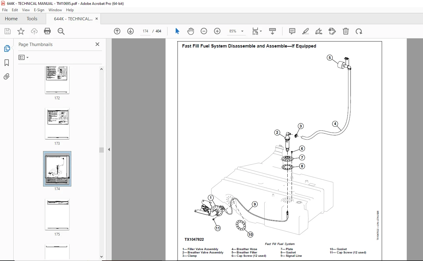
Fast Fill Fuel System Disassemble and Assemble—If Equipped174
Dampener Drive177
Elements179
Output Dampener Remove and Install179
Steering System181
Hydraulic System183
NeverGrease™ Pin Joints183
Orbital Steering Valve Remove and Install185
Steering Column Remove and Install187
Steering Column Disassemble and Assemble188
Steering Cylinders Remove and Install189
Steering Cylinder Bushings Remove and Install191
Secondary Steering Pump Remove and Install—If Equipped191
Secondary Steering Valve Remove and Install—If Equipped193
Joystick Steering Valve Remove and Install—If Equipped195
Joystick Steering Valve Disassemble and Assemble—If Equipped197
Loader Start-Up Procedure (Steering Cylinder)198
Service Brakes199
Active Elements201
Service Brake Assembly Remove and Install201
Service Brake Pedal and Linkage Disassemble and Assemble202
Hydraulic System203
Service Brake Valve Remove and Install203
Service Brake Accumulator Remove and Install204
Park Brake205
Active Elements207
Park Brake Remove and Install207
Park Brake Disassemble and Assemble210
Hydraulic System215
Park Brake Release Solenoid Valve Remove and Install215
Frame or Supporting Structure217
Frame Installation219
Welding Major Structure219
Engine and Loader Frame Separate220
Upper Pivot Bearing and Seals Remove and Install223
Lower Pivot Bearing and Seals Remove and Install224
Frame Bottom Guards227
Front Axle Guard Remove and Install227
Transmission Bottom Guard Remove and Install227
Chassis Weights229
Counterweights Remove and Install229
Rear Counterweight Remove and Install230
Operator’s Station231
Removal and Installation233
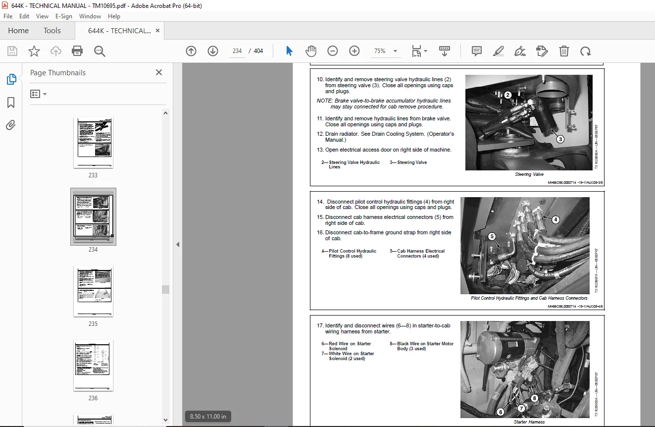
Cab Remove and Install233
Operator Enclosure237
Windowpanes Remove and Install237
Cab Door Hold-Open Release Adjust237
Front and Rear Windshield Wiper Motor Remove and Install238
Seat and Seat Belt243
Seat Remove and Install243
Seat Belt Remove and Install243
Joystick Steering Armrest and Wiring Harness Remove and Install—244
Joystick Steering Controller Assembly Remove and Install—If Equi246
Steering Joystick Disassemble and Assemble—If Equipped249
Joystick Steering Armrest Disassemble and Assemble—If Equipped257
Joystick Steering Armrest Tilt Pivot Disassemble and Assemble—If259
Joystick Steering Armrest Rear Pivot Adjustment—If Equipped262
Heating and Air Conditioning267
Proper Refrigerant Handling267
R134a Refrigerant Cautions267
R134a Compressor Oil Charge Check267
R134a Compressor Oil Removal267
R134a Component Oil Charge268
Refrigerant Leak Testing268
Refrigerant Hoses and Tubing Inspection269
R134a Refrigerant Recovery/Recycling and Charging Station Instal269
R134a System Recover270
R134a System Evacuate271
R134a System Charge272
Air Conditioner System Cleaning Procedures273
Air Conditioner System Purge273
Air Conditioner System Flush274
Air Conditioning Module With Heater/Evaporator Coil276
Heater/Evaporator Coil Remove and Install277
Expansion Valve Remove and Install278
Freeze Control Switch Remove and Install278
Freeze Control Switch Bench Test279
Heater Control Valve Remove and Install279
Heater Control Valve Leak Check279
Blower Motor Assembly Remove and Install280
Receiver-Dryer Remove and Install280
Condenser Remove and Install281
Air Conditioning High-Low Pressure Switch Remove and Install281
Fresh Air Filter Remove and Install282
Recirculating Air Filter Remove and Install283
Compressor Remove and Install284
Compressor Clutch—R134a Disassemble and Assemble285
Clutch Hub Clearance—R134a Check286
Sheet Metal and Styling287
Hood or Engine Enclosure289
Hood Remove and Install289
Engine Side Shields Remove and Install290
Loader294
Bucket295
Bucket Remove and Install295
Powerllel Pin-On Bucket Remove and Install298
Welded Bucket Cutting Edges Remove and Install299
Bucket Teeth Remove and Install299
Bolt-On Cutting Edges Remove and Install300
Cracked Cutting Edge Repair300
Frames301
NeverGrease™ Pin Joints301
Loader Bucket Tilt Linkage Remove and Install303
Bucket Linkage Seals and Bushings Remove and Install305
Loader Boom Bushings and Seals Remove and Install307
Boom Remove and Install309
Powerllel™ Leveling Link Disassemble and Assemble312
Powerllel™ Bellcrank Remove and Install316
Powerllel™ Bucket Cylinder Remove and Install320
Powerllel™ Bucket Link Disassemble and Assemble326
Powerllel™ Guide Links Remove and Install330
Powerllel™ Coupler Disassemble and Assemble334
Powerllel™ Loader Boom Disassemble and Assemble338
Hi-Vis Coupler Disassemble and Assemble344
Hydraulic System347
General Oil Cleanup Procedure347
Hydraulic Component Failure Cleanup Procedure349
Follow-Up Oil Cleanup Procedure351
Main Hydraulic Pump Remove and Install351
Loader Control Valve Remove and Install353
Loader Control Valve Disassemble and Assemble355
Boom Section Disassemble and Assemble356
Bucket Section Disassemble and Assemble357
Auxiliary Section Disassemble and Assemble—If Equipped358
Main Relief Valve Disassemble and Assemble359
Load Sense Relief Valve Disassemble and Assemble359
Circuit Relief With Anticavitation Valve Disassemble and Assembl360
Anticavitation Valve Disassemble and Assemble361
Auxiliary, Bucket, and Boom Section Pilot Orifice Check Valve362
Boom Cylinder Remove and Install362
Bucket Cylinder Remove and Install364
Boom and Bucket Cylinder Disassemble and Assemble365
Loader Start-Up Procedure366
Hydraulic Reservoir Remove and Install366
Pilot Control Valve Remove and Install368
Pilot Control Valve Disassemble and Assemble370
Auxiliary Function Pilot Control Valve Remove and Install—If Equ372
Auxiliary Function Pilot Control Valve Disassemble and Assemble—374
Pilot Accumulator Remove and Install376
Hydraulic Pump Manifold Remove and Install377
Hydraulic Pump Manifold Disassemble and Assemble378
Ride Control Valve Remove and Install—If Equipped380
Ride Control Valve Disassemble and Assemble—If Equipped382
Pin Disconnect Valve Remove and Install—If Equipped383
Pin Disconnect Valve Disassemble and Assemble—If Equipped384
Hydraulic Fan Pump Remove and Install385
Hydraulic Fan Motor Remove and Install386
Reversing Fan Valve Remove and Install—If Equipped387
Reversing Fan Valve Disassemble and Assemble—If Equipped389
Hydraulic Power Management Valve Remove and Install390
Hydraulic Power Management Valve Disassemble and Assemble391
Dealer Fabricated Tools393
Dealer Fabricated Tools395
DFT1132 Hydraulic Pump Removal and Installation Tool395
Page Number 3
Section 00 5
Group 0001 7
Section 01 21
Group 0110 23
Section 02 25
Group 0200 27
Group 0225 38
Group 0250 41
Group 0260 43
Section 03 47
Group 0300 49
Group 0350 51
Group 0360107
Section 04135
Group 0400137
Section 05147
Group 0505149
Group 0510151
Group 0520161
Group 0530167
Group 0560169
Section 07177
Group 0752179
Section 09181
Group 0960183
Section 10199
Group 1011201
Group 1060203
Section 11205
Group 1111207
Group 1160215
Section 17217
Group 1740219
Group 1746227
Group 1749229
Section 18231
Group 1800233
Group 1810237
Group 1821243
Group 1830267
Section 19287
Group 1910289
Section 31294
Group 3102295
Group 3140301
Group 3160347
Section 99393
Group 9900395
DESCRIPTION:
John Deere 644K Loader Repair Technical Manual TM10695 – PDF DOWNLOAD
- Foreword:
- This manual is written for an experienced technician. Essential tools required in performing certain service work are identified in this manual and are recommended for use.
- Live with safety: Read the safety messages in the introduction of this manual and the cautions presented throughout the text of the manual.
- This is the safety alert symbol. When you see this symbol on the machine or in this manual, be alert to the potential for personal injury.
- Technical manuals are divided in two parts: repair and operation and tests. Repair sections tell how to repair the components. Operation and tests sections help you identify the majority of routine failures quickly.
- Information is organized in groups for the various components requiring service instruction. At the beginning of each group are summary listings of all applicable essential tools, service equipment and tools, other materials needed to do the job, service parts kits, specifications, wear tolerances, and torque values.
- Technical Manuals are concise guides for specific machines. They are on the job guides containing only the vital information needed for diagnosis, analysis, testing, and repair.
- Fundamental service information is available from other sources covering basic theory of operation, fundamentals of troubleshooting, general maintenance, and basic type of failures and their causes.
G.B 06/01/25