Trusted Business
Verified & Licensed
Virus Free Files
100% Safe Downloads
Secure Payment
SSL Protected
Instant Delivery
Available Immediately
John Deere 644J Loader Operation and Test Technical Manual SN611232 PDF
$36.95
John Deere 644J Loader Operation and Test Technical Manual SN611232 – PDF DOWNLOAD
Instant PDF Download
Available immediately
Save to Your Device
Download & keep forever
Antivirus Scanned
100% virus-free
Trusted Worldwide
175,000+ customers
Description
John Deere 644J Loader Operation and Test Technical Manual SN611232 – PDF DOWNLOAD
FILE DETAILS:
John Deere 644J Loader Operation and Test Technical Manual SN611232 – PDF DOWNLOAD
Language : English
Pages : 1088
Downloadable : Yes
File Type : PDF
IMAGES PREVIEW OF THE MANUAL:
TABLE OF CONTENTS:
John Deere 644J Loader Operation and Test Technical Manual SN611232 – PDF DOWNLOAD
Contents 5
General Information 7
Safety Information 9
Recognize Safety Information 9
Follow Safety Instructions 9
Operate Only If Qualified 10
Wear Protective Equipment 10
Avoid Unauthorized Machine Modifications 10
Add Cab Guarding For Special Uses 11
Inspect Machine 11
Stay Clear of Moving Parts 11
Avoid High-Pressure Fluids 12
Avoid High-Pressure Oils 12
Beware of Exhaust Fumes 13
Prevent Fires 13
Prevent Battery Explosions 13
Handle Chemical Products Safely 14
Dispose of Waste Properly 14
Prepare for Emergencies 14
Use Steps and Handholds Correctly 15
Start Only From Operator’s Seat 15
Use and Maintain Seat Belt 15
Prevent Unintended Machine Movement 16
Avoid Work Site Hazards 17
Use Special Care When Operating Loader 18
Keep Riders Off Machine 18
Avoid Backover Accidents 19
Avoid Machine Tip Over 19
Operating on Slopes 20
Operating or Traveling On Public Roads 20
Inspect and Maintain ROPS 21
Add and Operate Attachments Safely 21
Prevent Unintended Detonation of Explosive Devices 21
Park And Prepare For Service Safely 22
Service Cooling System Safely 22
Remove Paint Before Welding or Heating 23
Make Welding Repairs Safely 24
Drive Metal Pins Safely 24
Diagnostic Trouble Codes (DTC) 25
CAN Monitor Unit (CMU) Diagnostic Trouble Codes 35
CAN Monitor Unit (CMU) Diagnostic Trouble Codes 35
00082905 — Fuel Level Open or Short 35
Fuel Level Sensor Open or Short Diagnostic Procedure 35
36
36
37
37
00200009 — Missing Message From ECU 37
ECU Signal Missing from CMU Diagnostic Procedure 38
38
38
39
39
39
39
00200309 — Missing Message From TCU 40
TCU Signal Missing from CMU Diagnostic Procedure 40
40
40
41
41
41
41
00203309 — Missing Message From FLC 42
FLC Signal Missing from CMU Diagnostic Procedure 42
42
42
43
43
43
43
00214009 — Missing Message From SSM 44
SSM Signal Missing from CMU Diagnostic Procedure 44
44
44
45
45
45
45
00236704 — Left Turn Switch Short to Ground 45
Left Turn Switch Short to Ground Diagnostic Procedure 46
46
46
47
47
00236904 — Right Turn Switch Short to Ground 47
Right Turn Switch Short to Ground Diagnostic Procedure 47
48
48
48
48
52425031 — Inspect Park Brake 49
Inspect Park Brake Diagnostic Procedure 49
49
Engine Control Unit (ECU) Diagnostic Trouble Codes 51
Engine Control Unit (ECU) Diagnostic Trouble Codes 51
00010700 — Eng Air Filter Restricted 51
Engine Air Filter Restricted Diagnostic Procedure 52
52
52
52
52
00017103 — Ambient Air Open Circuit 53
Ambient Air Open Circuit Diagnostic Procedure 53
53
54
54
00017104 — Ambient Air Short to Gnd 54
Ambient Air Short to Ground Diagnostic Procedure 55
55
56
56
57
00062701 — ECU Unswitch Short to GND 57
Engine Control Unit (ECU) Unswitched Short to Ground Diagnostic Procedure 57
57
57
58
58
00067605 — Engine Heat Open or Short 58
Engine Heat Open or Short Diagnostic Procedure 58
58
59
59
00125313 — Injector Cal Required 59
Injector Calibration Required Diagnostic Procedure 60
60
60
00200309 — CAN Comm Lost for TCU 60
CAN Communication Lost for TCU Diagnostic Procedure 60
61
61
61
61
62
00203309 — CAN Comm Lost for FLC 62
CAN Communication Lost for FLC Diagnostic Procedure 62
62
63
63
63
63
64
Transmission Control Unit (TCU) Diagnostic Trouble Codes 65
Transmission Control Unit (TCU) Diagnostic Trouble Codes 65
00202309 — CAN Comm Lost for CMU 65
CAN Signal Missing from CMU Diagnostic Procedure 66
66
66
67
67
67
68
68
00203309 — CAN Comm Lost for FLC 68
CAN Signal Missing from FLC Diagnostic Procedure 68
68
69
69
69
69
70
52234400 — Converter Overtemp 70
Transmission Oil Temperature Too High Diagnostic Procedure 70
70
71
71
52235015 — Input Torque Overload 71
Input Torque Overload Diagnostic Procedure 71
72
72
72
52236407 — Trans Clutch Calibr Failed 72
Transmission Clutch Calibration Failed Diagnostic Procedure 73
73
73
73
73
52236413 — Trans Clutch Calibr Fault 74
Transmission Clutch Calibration Fault Diagnostic Procedure 74
74
52236513 — Limp Home Mode 74
Limp Home Mode Requested Diagnostic Procedure 75
75
75
75
52236613 — Application Invalid 75
Application Invalid Diagnostic Procedure 76
76
76
52236713 — TCU Configuration Invalid 76
TCU Configuration Invalid Diagnostic Procedure 77
77
77
52236802 — Memory Failure 77
TCU Memory Failure Diagnostic Procedure 78
78
78
52236903 — Remote Display Short to Power 78
Remote Display Short to Power Diagnostic Procedure 79
79
79
80
80
80
52236904 — Remote Display Short to Ground 81
Remote Display Short to Ground Diagnostic Procedure 81
81
81
82
82
82
52237002 — TCU VP2 Short Circuit 82
TCU Valve Power Supply 2 Short Circuit Diagnostic Procedure 83
83
83
84
84
52237102 — TCU VP1 Short Circuit 84
TCU Valve Power Supply 1 Short Circuit Diagnostic Procedure 85
85
85
52237303 — Power Supply High Voltage 85
Power Supply High Voltage Diagnostic Procedure 86
86
86
86
52237304 — Power Supply Low Voltage 87
Power Supply Low Voltage Diagnostic Procedure 87
87
87
88
88
52237403 — Sensor Supply Short to Power 88
Sensor Supply Short to Power Diagnostic Procedure 88
89
89
89
89
52237404 — Sensor Supply Short to Gnd 90
Sensor Supply Short to Ground Diagnostic Procedure 90
90
91
91
91
91
52237500 — Trans Oil Filter Restricted 92
Transmission Oil Filter Restricted Diagnostic Procedure 92
92
93
93
93
52237600 — Trans Oil Temp Max Value 94
Transmission Oil Temperature Maximum Value Diagnostic Procedure 94
94
95
52237903 — Park Brake Solenoid Short to Power 95
Park Brake Solenoid Short to Power Diagnostic Procedure 95
96
96
97
97
52237904 — Park Brake Solenoid Short to Gnd 98
Park Brake Solenoid Short to Ground Diagnostic Procedure 98
98
99
100
100
52237905 — Park Brake Solenoid Open Circuit 101
Park Brake Solenoid Open Circuit Diagnostic Procedure 101
101
102
102
52238203 — Backup Alarm Short to Power 102
Backup Alarm Short to Power Diagnostic Procedure 103
103
104
105
105
52238204 — Backup Alarm Short to Gnd 106
Backup Alarm Short to Ground Diagnostic Procedure 106
106
106
107
108
108
52238205 — Backup Alarm Open Circuit 109
Backup Alarm Open Circuit Diagnostic Procedure 109
109
109
110
110
52238302 — Clutch KR Slippage 111
Clutch KR Slippage Diagnostic Procedure 111
111
111
112
112
112
113
113
52238303 — Clutch Rev Sol Short to Power 113
Clutch Reverse Solenoid Short to Power Diagnostic Procedure 113
114
114
115
115
52238304 — Clutch Rev Sol Short to Gnd 115
Clutch Reverse Solenoid Short to Ground Diagnostic Procedure 116
116
117
118
119
119
52238305 — Clutch Rev Sol Open Circuit 119
Clutch Reverse Solenoid Open Circuit Diagnostic Procedure 120
120
121
121
52238602 — Clutch KV Slippage 121
Clutch KV Slippage Diagnostic Procedure 122
122
122
122
123
123
123
124
52238603 — Clutch Fwd Sol Short to Power 124
Clutch Forward Solenoid Short to Power Diagnostic Procedure 124
124
125
126
126
52238604 — Clutch Fwd Sol Short to Gnd 126
Clutch Forward Solenoid Short to Ground Diagnostic Procedure 127
127
128
129
130
130
52238605 — Clutch Fwd Sol Solenoid Open 130
Clutch Forward Solenoid Open Circuit Diagnostic Procedure 131
131
132
132
52238902 — Clutch K4 Slippage 132
Clutch K4 Slippage Diagnostic Procedure 133
133
133
133
134
134
134
135
52238903 — Clutch K4 Sol Short to Power 135
Clutch K4 Control Solenoid Short to Power Diagnostic Procedure 135
135
136
137
137
52238904 — Clutch K4 Sol Short to Gnd 137
Clutch K4 Control Solenoid Short to Ground Diagnostic Procedure 138
138
139
140
141
141
52238905 — Clutch K4 Sol Open Circuit 141
Clutch K4 Control Solenoid Open Circuit Diagnostic Procedure 142
142
143
143
52239202 — Clutch K3 Slippage 143
Clutch K3 Slippage Diagnostic Procedure 143
144
144
144
144
145
145
145
52239203 — Clutch K3 Sol Short to Power 146
Clutch K3 Control Solenoid Short to Power Diagnostic Procedure 146
146
147
148
148
52239204 — Clutch K3 Sol Short to Gnd 148
Clutch K3 Control Solenoid Short to Ground Diagnostic Procedure 149
149
150
151
152
152
52239205 — Clutch K3 Sol Open Circuit 152
Clutch K3 Control Solenoid Open Circuit Diagnostic Procedure 153
153
154
154
52239502 — Clutch K2 Slippage 154
Clutch K2 Slippage Diagnostic Procedure 154
155
155
155
155
156
156
156
52239503 — Clutch K2 Sol Short to Power 157
Transmission Clutch K2 Control Solenoid Short to Power Diagnostic Procedure 157
157
158
159
159
52239504 — Clutch K2 Sol Short to Gnd 159
Transmission Clutch K2 Control Solenoid Short to Ground Diagnostic Procedure 160
160
161
162
163
163
52239505 — Clutch K2 Sol Open Circuit 163
Transmission Clutch K2 Control Solenoid Open Circuit Diagnostic Procedure 164
164
165
165
52239902 — Clutch K1 Slippage 165
Transmission Clutch K1 Slippage Diagnostic Procedure 166
166
166
166
167
167
167
168
52239903 — Clutch K1 Sol Short to Power 168
Transmission Clutch K1 Control Solenoid Short to Power Diagnostic Procedure 168
168
169
170
170
52239904 — Clutch K1 Sol Short to Gnd 170
Transmission Clutch K1 Control Solenoid Short to Ground Diagnostic Procedure 171
171
172
173
174
174
52239905 — Clutch K1 Sol Open Circuit 174
Transmission Clutch K1 Control Solenoid Open Circuit Diagnostic Procedure 175
175
176
176
52240102 — Trans Speed Sensor Fault 176
Transmission Output Speed Sensor Fault Diagnostic Procedure 177
177
177
52240103 — Output Shaft Open or Short 178
Output Shaft Open or Short Diagnostic Procedure 178
178
179
180
180
52240104 — Output Shaft Short to Gnd 181
Output Shaft Short to Ground Diagnostic Procedure 181
181
182
182
52240112 — Output Shaft Fault 183
Output Shaft Fault Diagnostic Procedure 183
183
184
52240115 — Output Shaft Overspeed 184
Output Shaft Overspeed Diagnostic Procedure 184
185
52240203 — Clutch Speed Open or Short 185
Clutch Speed Open or Short Diagnostic Procedure 185
186
186
187
188
188
52240204 — Clutch Speed Short to Gnd 189
Clutch Speed Short to Ground Diagnostic Procedure 189
189
190
191
191
52240212 — Clutch Speed Sensor Fault 192
Clutch Speed Sensor Fault Diagnostic Procedure 192
192
193
193
52240303 — Conv Output Spd Open or Short 193
Converter Output Speed Open or Short Diagnostic Procedure 193
194
194
195
196
196
52240304 — Conv Output Spd Short to Gnd 197
Converter Output Speed Short to Ground Diagnostic Procedure 197
197
198
199
199
52240312 — Conv Output Spd Fault 200
Converter Output Speed Fault Diagnostic Procedure 200
200
201
201
52240403 — Conv Input Spd Open or Short 201
Converter Input Speed Open or Short Diagnostic Procedure 201
202
202
203
204
204
52240404 — Conv Input Spd Short to Gnd 205
Torque Converter Input Speed Short to Ground Diagnostic Procedure 205
205
206
207
207
52240412 — Conv Input Spd Fault 208
Converter Input Speed Fault Diagnostic Procedure 208
208
209
209
52240603 — Trans Oil Temp Open or Short 209
Transmission Oil Temperature Sensor Open or Short Diagnostic Procedure 209
210
211
212
213
213
52240604 — Trans Oil Temp Short to Gnd 214
Transmission Oil Temperature Sensor Short to Ground Diagnostic Procedure 214
215
216
217
217
52240703 — Clutch Cutoff Short to Power 218
Clutch Cut-Off Sensor Short to Power Diagnostic Procedure 218
218
219
219
219
219
52240704 — Clutch Cutoff Open or Short 220
Clutch Cut-Off Sensor Open or Short Diagnostic Procedure 220
220
221
221
221
221
52240905 — 2nd FNR Open Circuit 222
2nd TCL Open Circuit Diagnostic Procedure (Pilot Control Joystick) 222
222
223
223
52240912 — 2nd FNR Mult Inputs 223
2nd TCL Missing Inputs Diagnostic Procedure 223
224
224
224
225
225
52241105 — 1st FNR Open Circuit 225
1st TCL Open Circuit Diagnostic Procedure (Steering Column Shifter) 225
226
226
227
1st TCL Open Circuit Diagnostic Procedure (Pilot Control Joystick) 227
227
228
228
52241112 — 1st FNR Mult Inputs 228
1st TCL Multiple Inputs Diagnostic Procedure (Steering Column Shifter) 228
229
229
230
231
231
1st TCL Multiple Inputs Diagnostic Procedure (Pilot Control Joystick) 231
232
232
232
233
233
52241212 — Gear Selection Error 233
Gear Selection Error Diagnostic Procedure 233
234
234
235
235
52241902 — Clutch Cutoff Disabled 235
Clutch Cut-Off Disabled Diagnostic Procedure 236
236
236
236
237
52242002 — Manual Downshift Disabled 237
Manual Downshift Disabled Diagnostic Procedure 237
237
237
238
52242102 — Auto To 1st Disabled 238
Auto To 1st Disabled Diagnostic Procedure 238
238
239
239
52404800 — Trans Output Torque Exceeded 239
Trans Output Torque Exceeded Diagnostic Procedure 239
240
240
52404900 — Trans Input Torque Exceeded 240
Trans Input Torque Exceeded Diagnostic Procedure 240
241
241
52428700 — Configure Machine Model 241
Configure Machine Model Diagnostic Procedure 241
242
Flex Load Controller (FLC) Diagnostic Trouble Codes 243
Flex Load Controller (FLC) Diagnostic Trouble Codes 243
00011701 — Brake Pressure Low 243
Brake Pressure Low Diagnostic Procedure 243
244
244
244
00016716 — Alternator High Voltage 245
Alternator High Voltage Diagnostic Procedure 245
245
245
245
00016718 — Alternator Low Voltage 246
Alternator Low Voltage Diagnostic Procedure 246
246
246
246
247
00016816 — High Battery Voltage 247
High Battery Voltage Diagnostic Procedure 247
247
247
248
00016818 — Low Battery Voltage 248
Low Battery Voltage Diagnostic Procedure 248
248
248
249
249
00044405 — 12V Cntr Tap Open or Short 249
12 Volt Center Tap Open or Short Diagnostic Procedure 249
250
251
251
00044418 — Battery Voltage Imbalance 251
Battery Voltage Imbalance Diagnostic Procedure 252
252
252
253
00054419 — Refer Torq Mis-Match 253
Reference Torque MisMatch Diagnostic Procedure 253
253
00062812 — Controller Not Programmed 253
Controller Not Programmed Diagnostic Procedure 254
254
00077404 — JS Upshift Short to Gnd 254
Joystick Upshift Short to Ground Diagnostic Procedure 254
255
255
255
255
00077410 — JS Upshift Button Stuck 256
Joystick Upshift Button Stuck Diagnostic Procedure 256
256
256
257
257
00077504 — JS Downshift Short to Gnd 257
Joystick Downshift Short to Ground Diagnostic Procedure 257
258
258
258
258
00077510 — JS Downshift Button Stuck 259
Joystick Downshift Button Stuck Diagnostic Procedure 259
259
259
260
260
00078503 — Pilot Solenoid Short to Power 260
Pilot Solenoid Short to Power Diagnostic Procedure 260
261
261
262
262
00078505 — Pilot Solenoid Open Circuit 262
Pilot Solenoid Open Circuit Diagnostic Procedure 262
263
263
263
00078506 — Pilot Solenoid High Current 264
Pilot Solenoid High Current Diagnostic Procedure 264
264
265
265
265
00088003 — Brake Lights Short to Power 266
Brake Lights Short to Power Diagnostic Procedure 266
266
267
268
268
00088005 — Brake Lights Open Circuit 268
Brake Lights Open Circuit Diagnostic Procedure 269
269
270
270
00088006 — Brake Lights High Current 271
Brake Lights High Current Diagnostic Procedure 271
271
272
273
273
00097703 — Rev Fan Solenoid Short to Power 273
Reverse Fan Solenoid Short to Power Diagnostic Procedure 274
274
275
276
276
00097705 — Rev Fan Sol Open Circuit 276
Reverse Fan Solenoid Open Circuit Diagnostic Procedure 277
277
278
278
00097706 — Rev Fan Sol High Current 279
Reverse Fan Solenoid High Current Diagnostic Procedure 279
279
280
281
281
00104504 — Brake Lt Sw Shorted to Gnd 281
Brake Light Switch Shorted to Ground Diagnostic Procedure 282
282
282
283
283
00106902 — Tire Size Incorrect 283
Tire Size Incorrect Diagnostic Procedure 283
283
284
00107131 — Fan Speed Sol Circuit Fault 284
Fan Speed Solenoid Circuit Fault Diagnostic Procedure 284
284
285
287
287
00107500 — Fuel Pump On Too Long 288
Fuel Pump On Too Long Diagnostic Procedure 288
288
00107904 — FLC Sensor 1 Voltage Low 288
FLC Sensor 1 Voltage Low Diagnostic Procedure 289
289
290
290
00108004 — FLC Sensor 2 Voltage Low 290
FLC Sensor 2 Voltage Low Diagnostic Procedure 291
291
291
291
00163800 — Hydraulic Oil High Temp 292
Hydraulic Oil High Temperature Diagnostic Procedure 292
292
00163804 — Hyd Oil Temp Circuit Short to Gnd 293
Hydraulic Oil Temperature Circuit Short to Ground Diagnostic Procedure 293
293
294
294
294
00171301 — Hyd Oil Filter Restricted 295
Hydraulic Oil Filter Restricted Diagnostic Procedure 295
295
296
296
296
00176203 — Hyd Pressure Short to Power 297
Hydraulic Pressure Short to Power Diagnostic Procedure 297
297
298
298
298
00176204 — Hyd Pressure Open or Short 299
Hydraulic Pressure Open or Short Diagnostic Procedure 299
300
301
301
301
00200009 — CAN Comm Lost for ECU 302
CAN Communication Lost For ECU Diagnostic Procedure 302
302
302
303
303
303
00200309 — CAN Comm Lost for TCU 304
CAN Communication Lost for TCU Diagnostic Procedure 304
304
304
305
305
305
00202309 — CAN Comm Lost for CMU 306
CAN Communication Lost for CMU Diagnostic Procedure 306
306
307
307
307
308
308
00214009 — CAN Comm Lost for SSM 308
CAN Communication Lost for SSM Diagnostic Procedure 308
308
308
309
309
309
00235005 — Drive Lamps Open or Short 309
Drive Lamps Open or Short Diagnostic Procedure 310
310
310
311
312
312
00235006 — Drive Lamps High Current 312
Drive Lamps High Current Diagnostic Procedure 313
313
313
314
314
00235505 — Front Work Lts Open or Short 314
Auxiliary Lights Open or Short Diagnostic Procedure 315
315
316
317
318
318
00235506 — Front Work Lts High Current 319
Auxiliary Lights High Current Diagnostic Procedure 319
319
320
321
321
00235605 — Front Work Lts Open or Short 322
Front Work Lights Open or Short Diagnostic Procedure 322
322
323
324
325
325
00235606 — Front Work Lts High Current 326
Front Work Lights High Current Diagnostic Procedure 326
326
327
328
328
00236205 — Rear Work Lts Open or Short 329
Rear Work Lights Open or Short Diagnostic Procedure 329
329
330
331
332
332
00236206 — Rear Work Lts High Current 333
Rear Work Lights High Current Diagnostic Procedure 333
333
334
335
335
00236803 — Left Turn Lts Circuit Short to Power 336
Left Turn Lights Circuit Short to Power Diagnostic Procedure 336
336
337
338
339
340
340
00236805 — Left Turn Lts Open Circuit 340
Left Turn Lights Open Circuit Diagnostic Procedure 341
341
342
343
343
00236806 — Left Turn Lts Circuit High Current 344
Left Turn Lights Circuit High Current Diagnostic Procedure 344
344
345
346
347
348
348
00237003 — Right Turn Lts Short to Power 348
Right Turn Lights Short to Power Diagnostic Procedure 349
349
349
350
351
351
00237005 — Right Turn Lts Open Circuit 351
Right Turn Lights Open Circuit Diagnostic Procedure 352
352
352
353
353
00237006 — Right Turn Lts High Current 354
Right Turn Lights High Current Diagnostic Procedure 354
354
355
356
357
358
358
00237803 — Marker/Tail Lts Short to Power 358
Marker/Tail Lights Short to Power Diagnostic Procedure 359
359
360
361
362
363
363
00237805 — Marker/Tail Lts Open Circuit 363
Marker/Tail Lights Open Circuit Diagnostic Procedure 364
364
365
366
366
00237806 — Marker/Tail Lts High Current 367
Marker/Tail Lights High Current Diagnostic Procedure 367
367
368
369
370
371
371
00238606 — Beacon Light High Current 371
Beacon Light High Current diagnostic Procedure 372
372
372
373
373
00269702 — JS Mag Out of Range 373
Joystick Magnitude Out of Range Diagnostic Procedure 373
374
00287504 — 4-Way Flash Sw Short to Gnd 374
4-Way Flasher Switch Short to Ground Diagnostic Procedure 374
374
375
375
375
29926102 — Machine Config Invalid 375
Machine Configuration Invalid Diagnostic Procedure 376
376
376
52243102 — Memory Test Failure 376
Memory Test Failure Diagnostic Procedure 376
377
52243205 — R Wiper H-Spd Open Circuit 377
Rear Wiper High-Speed Open Circuit Diagnostic Procedure 377
377
378
378
52243206 — R Wiper H-Spd High Current 378
Rear Wiper High-Speed High Current Diagnostic Procedure 379
379
379
380
380
52243305 — R Wiper L-Spd Open or Short 380
Rear Wiper Low-Speed Open or Short Diagnostic Procedure 381
381
381
382
383
383
52243306 — R Wiper L-Spd High Current 383
Rear Wiper Low-Speed High Current Diagnostic Procedure 384
384
384
385
385
52243405 — F Wiper L-Spd Open or Short 385
Front Wiper Low-Speed Open or Short Diagnostic Procedure 386
386
386
387
388
388
52243406 — F Wiper L-Spd High Current 388
Front Wiper Low-Speed High Current Diagnostic Procedure 389
389
389
390
390
52243505 — F Wiper H-Spd Open Circuit 390
Front Wiper High-Speed Open Circuit Diagnostic Procedure 391
391
392
392
52243506 — F Wiper H-Spd High Current 392
Front Wiper High-Speed High Current Diagnostic Procedure 393
393
393
394
394
52243603 — Bucket Pos Short to Power 394
Bucket Position Short to Power Diagnostic Procedure 395
395
396
397
397
52243604 — Bucket Pos Open or Short 397
Bucket Position Open or Short Diagnostic Procedure 398
398
398
399
400
400
52243704 — RTDig Switch 1 Short to Gnd 400
Return-to-dig Switch 1 Short to Ground Diagnostic Procedure 401
401
401
402
402
52243803 — Pin Disc Sol Short to Power 402
Pin Disconnect Solenoid Short to Power Diagnostic Procedure 403
403
404
405
405
52243805 — Pin Disc Sol Open Circuit 405
Pin Disconnect Solenoid Open Circuit Diagnostic Procedure 406
406
407
407
52243806 — Pin Disc Sol High Current 407
Pin Disconnect Solenoid High Current Diagnostic Procedure 408
408
409
410
410
52279605 — R Washer Pump Open Circuit 410
Rear Washer Pump Open Circuit Diagnostic Procedure 411
411
411
412
52279606 — R Washer Pump High Current 412
Rear Washer Pump High Current Diagnostic Procedure 412
412
413
413
413
52279705 — F Washer Pump Open Circuit 414
Front Washer Pump Open Circuit Diagnostic Procedure 414
414
415
415
52279706 — F Washer Pump High Current 415
Front Washer Pump High Current Diagnostic Procedure 416
416
416
417
417
52313704 — Steering Press Sw Shrt to Gnd 417
Steering Pressure Switch Short to Ground Diagnostic Procedure 418
418
418
418
419
52321405 — No Voltage to FLC on VP6 419
No Voltage to FLC on VP6 Diagnostic Procedure 419
419
419
420
420
420
52321505 — No Voltage to FLC on VP5 420
No Voltage to FLC on VP5 Diagnostic Procedure 421
421
421
421
422
422
52321605 — No Voltage to FLC on VP4 422
No Voltage to FLC on VP4 Diagnostic Procedure 422
423
423
423
423
52321705 — No Voltage to FLC on VP3 424
No Voltage to FLC on VP3 Diagnostic Procedure 424
424
424
425
425
52321805 — No Voltage to FLC on VP2 425
No Voltage to FLC on VP2 Diagnostic Procedure 425
426
426
426
426
52321905 — No Voltage to FLC on VP1 427
No Voltage to FLC on VP1 Diagnostic Procedure 427
427
427
428
428
52343617 — FLC Watchdog Timed Out 428
FLC Watchdog Timed Out Diagnostic Procedure 428
428
429
52357703 — 2nd Steer Pump Short to Power 429
Secondary Steering Pump Short to Power Diagnostic Procedure 429
430
431
431
52357705 — 2nd Steer Pump Open Circuit 431
Secondary Steering Pump Open Circuit Diagnostic Procedure 432
433
433
52357706 — 2nd Steer Pump High Current 434
Secondary Steer Pump High Current Diagnostic Procedure 434
435
436
436
52378603 — Boom Position Short to Power 436
Boom Position Short to Power Diagnostic Procedure 437
437
437
438
438
52378604 — Boom Position Open or Short 438
Boom Position Open or Short Diagnostic Procedure 439
439
439
440
441
441
52384001 — Brake Pressure Low-Front 441
Brake Pressure Low-Front Diagnostic Procedure 442
442
52384003 — Ft Brake Pressure Short to Power 442
Front Brake Pressure Sensor Short to Power Diagnostic Procedure 442
443
443
443
443
52384004 — Ft Brake Pressure Open or Short 444
Front Brake Pressure Sensor Open or Short Diagnostic Procedure 444
444
444
445
445
445
52391131 — Hyd Pwr Sol Circuit Fault 445
52394803 — Ride Contrl Sol Short to Power 446
Ride Control Solenoid Short to Power Diagnostic Procedure 446
446
447
447
448
52394805 — Ride Contrl Sol Open Circuit 448
Ride Control Solenoid Open Circuit Diagnostic Procedure 448
448
449
449
52394806 — Ride Contrl Sol High Current 449
Ride Control Solenoid High Current Diagnostic Procedure 450
450
450
451
451
52426519 — Check Sum Error 451
Check Sum Error Diagnostic Procedure 452
452
Sealed Switch Module (SSM) Diagnostic Trouble Codes 453
Sealed Switch Module (SSM) Diagnostic Trouble Codes 453
00062812 — Controller Not Programmed 453
Controller Not Programmed Diagnostic Procedure 454
454
00062912 — SSM Watchdog Time Out 454
SSM Watchdog Time Out Diagnostic Procedure 454
455
455
00063912 — SSM Lost Message 455
SSM Lost Message Diagnostic Procedure 455
456
456
456
456
00063919 — SSM Lost CAN Communications 456
SSM Lost CAN Communications Diagnostic Procedure 457
457
457
457
457
00203309 — SSM Lost Communications 458
SSM Lost Communications Diagnostic Procedure 458
458
458
459
459
459
52352310 — Rear Wiper Keypad Stuck 460
Rear Wiper Keypad Stuck Diagnostic Procedure 460
460
460
460
461
52352410 — Front Wiper Keypad Stuck 461
Front Wiper Keypad Stuck Diagnostic Procedure 461
461
461
462
462
52352510 — Front Washer Keypad Stuck 462
Front Washer Keypad Stuck Diagnostic Procedure 462
462
463
463
463
52352610 — Reverse Fan Keypad Stuck 463
Reverse Fan Keypad Stuck Diagnostic Procedure 463
464
464
464
464
52352710 — Pin Disconnect Keypad Stuck 464
Pin Disconnect Keypad Stuck Diagnostic Procedure 465
465
465
465
465
52352810 — A/C Keypad Stuck 466
A/C Keypad Stuck Diagnostic Procedure 466
466
466
466
467
52352910 — Work Lights Keypad Stuck 467
Work Lights Keypad Stuck Diagnostic Procedure 467
467
467
468
468
52353010 — Beacon Light Keypad Stuck 468
Beacon Light Keypad Stuck Diagnostic Procedure 468
468
469
469
469
52353210 — Spin Control Keypad Stuck 469
Spin Control Keypad Stuck Diagnostic Procedure 469
470
470
470
470
52353310 — Clutch Cut-Off Keypad Stuck 470
Clutch Cut-Off Keypad Stuck Diagnostic Procedure 471
471
471
471
471
52353410 — Pilot Enable Keypad Stuck 472
Pilot Enable Keypad Stuck Diagnostic Procedure 472
472
472
472
473
52353510 — Ride Control Keypad Stuck 473
Ride Control Keypad Stuck Diagnostic Procedure 473
473
473
474
474
52353610 — Auto Transmission Keypad Stuck 474
Auto Transmission Keypad Stuck Diagnostic Procedure 474
474
475
475
475
52353710 — Drive Lights Keypad Stuck 475
Drive Lights Keypad Stuck Diagnostic Procedure 475
476
476
476
476
52353810 — Keypad Not Used 476
Keypad Not Used Diagnostic Procedure 477
477
477
477
477
52360710 — Return to Dig Keypad Stuck 478
Return-to-Dig Keypad Stuck Diagnostic Procedure 478
478
478
478
479
52360810 — BHKO Keypad Stuck 479
Boom Height Kickout Keypad Stuck Diagnostic Procedure 479
479
479
480
480
52360910 — RTCarry Keypad Stuck 480
Return-to-Carry Keypad Stuck Diagnostic Procedure 480
480
481
481
481
52361010 — Rear Washer Keypad Stuck 481
Rear Washer Keypad Stuck Diagnostic Procedure 481
482
482
482
482
Operational Checkout Procedure 483
Operational Checkout Procedure 485
Operational Checkout 485
Diagnostic Trouble Code Check 485
485
Operational Checks—Key Switch OFF, Engine OFF Checks 485
486
486
486
Operational Checks—Key Switch ON, Engine OFF Checks 486
487
487
488
488
489
Operational Checks—Key Switch ON, Engine ON Checks 489
489
490
491
491
492
493
494
495
495
496
497
497
498
498
498
499
499
500
500
501
501
501
502
502
503
Engine 505
Theory Of Operation 507
PowerTech Plus™ 68L (6068) John Deere Engine 507
Cold Weather Starting Aid 507
Diagnostic Information 509
PowerTech Plus™ 68L (6068) John Deere Engine 509
Engine Cooling System Component Location 510
Engine Fuel System Component Location 511
Engine Intake and Exhaust Component Location 514
Tests 517
Engine Speed Check and Adjust 517
Electrical System 521
System Information 524
Electrical Diagram Information 524
System Diagrams 532
Fuse and Relay Specifications 532
System Functional Schematic, Wiring Diagram and Component Location Legend 534
System Functional Schematic and Section Legend 540
JDLink™ System Functional Schematic—If Equipped (SN 615706— ) 556
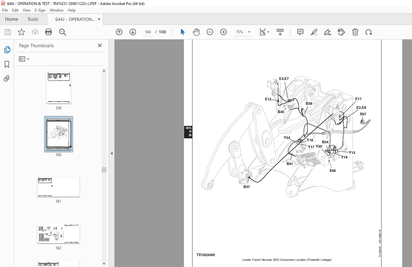
Loader Frame Harness (W2) Component Location 558
Loader Frame Harness (W2) Wiring Diagram 562
Load Center Harness (W3) Component Location 566
Load Center Harness (W3) Wiring Diagram 568
Front Console Harness (W4) Component Location 596
Front Console Harness (W4) Wiring Diagram 598
Engine Frame Harness (W5) Component Location 600
Engine Frame Harness (W5) Wiring Diagram 602
Engine Harness (W6) Component Location 606
Engine Harness (W6) Wiring Diagram 610
Transmission Harness (W10) Component Location 614
Transmission Harness (W10) Wiring Diagram 616
Rear Frame Harness (W13) Component Location 618
Rear Frame Harness (W13) Wiring Diagram 622
Secondary Steering Harness (W17) Component Location 624
Secondary Steering Harness (W17) Wiring Diagram 626
Cab Roof Harness (W19) Component Location 628
Cab Roof Harness (W19) Wiring Diagram 630
Heater and Air Conditioner Harness (W20) Component Location 632
Heater and Air Conditioner Harness (W20) Wiring Diagram 634
JDLink™ System Harnesses (W29, and W30) Component Location—If Equipped (S N 615706— ) 636
GlobalTRACS® Terminal (GTT) Harness (W29) Wiring Diagram—If Equipped (SN 615706— ) 638
Machine Information Gateway (MIG) Harness (W30) Wiring Diagram—If Equipped (SN 615706— ) 640
Radio Harness (W34) Component Location 642
Radio Harness (W34) Wiring Diagram 644
Sub-System Diagnostics 647
Starting and Charging Circuit Theory of Operation 647
Controller Area Network (CAN) Theory of Operation 650
Engine Control Unit (ECU) Circuit Theory of Operation 652
Flex Load Controller (FLC) Circuit Theory of Operation 661
Transmission Control Unit (TCU) Circuit Theory of Operation 677
CAN Monitor Unit (CMU) Circuit Theory of Operation 681
References 683
Diagnostic Trouble Codes (DTC) Quick Reference List 683
SERVICE ADVISOR Diagnostic Application 690
SERVICE ADVISOR Connection Procedure 691
Reading Diagnostic Trouble Codes with SERVICE ADVISOR Diagnostic Application 693
JDLink™ Connection Procedure—If Equipped (SN 615706— ) 696
CAN Monitor Unit (CMU) Menu Structure—Service Mode 697
Flex Load Controller (FLC) Fault Exceptions 715
CAN Circuit Test 717
Controller Area Network (CAN) Diagnostics 717
718
718
719
720
721
721
722
Electrical Component Specifications 723
Transmission Control Valve Solenoid Check 729
Clutch Cut-Off Sensor Check and Adjustment 730
Boom Height Kickout/Return-to-Carry Adjustment 731
Return-to-Dig Adjustment—Z-Bar Linkage 732
Return-To-Dig Adjustment—Powerllel™ Linkage 733
Sensor Circuitry Check 734
Diagnostic Trouble Codes—After Machine Repair 737
Change Backup Alarm Volume 738
Pressure Switches Remove and Install 739
Alternator Test Procedure 740
Replace (Push Type) Metri-Pack Connectors 742
Replace METRI-PACK Connectors 743
Install METRI-PACK Contact 744
Replace DEUTSCH Connectors 745
Install DEUTSCH Contact 746
Replace WEATHER PACK Connector 748
Install WEATHER PACK Contact 749
Replace CINCH Connectors 750
Install CINCH Contact 752
Repair 32 and 48 Way CINCH Connectors 753
Remove Connector Body from Blade Terminals 756
Engine Control Unit (ECU) Remove and Install 756
Flex Load Controller (FLC) Remove and Install 758
Transmission Control Unit (TCU) Remove and Install 759
Sealed Switch Module (SSM) Remove and Install 760
CAN Monitor Unit (CMU) Remove and Install 761
Reprogram CAN Monitor Unit (CMU) 761
Electronic Controller Reconfiguration 763
Power Train 765
Theory of Operation 767
TEAMMATE™ Axles 767
Transmission Clutch Engagement and Solenoids Activated 767
Power Train Component Operation 768
Transmission Operation 770
Transmission Operation—First Gear Forward 772
Transmission Control Valve Component Operation 775
Transmission Clutch Modulation 778
Thermal Bypass Valve Operation 780
Standard Differential Operation 782
Differential Lock Operation 783
Axle Circulation Dual Pump Operation 784
Park Brake Operation 786
Diagnostic Information 792
Transmission Control Circuit—First Forward 792
Transmission Control System 794
Power Train Component Location 796
Transmission System Diagnose Malfunctions 799
Transmission Clutch Slippage Diagnostic Procedure 799
799
799
799
800
800
800
800
800
800
801
801
Machine Will Not Move in Either Direction Diagnostic Procedure 801
801
801
802
802
802
802
802
803
803
803
803
803
804
804
804
Machine Will Not Engage in Low Gear Diagnostic Procedure 804
804
804
805
805
805
805
Machine Will Not Shift Correctly Diagnostic Procedure 805
805
806
806
Transmission System Pressure Is Low in Neutral Diagnostic Procedure 806
806
806
806
807
Transmission Pressure Is Low (One or Two Gear Ranges) Diagnostic Procedure 807
807
807
807
Transmission Shifts Too Slow Diagnostic Procedure 807
808
808
808
808
809
809
809
809
Transmission Shifts Too Fast Diagnostic Procedure 809
809
809
810
810
Machine Creeps in Neutral Diagnostic Procedure 810
810
810
810
Transmission Hydraulic System Overheats Diagnostic Procedure 811
811
811
811
811
811
811
812
812
812
Transmission Excessive Noise Diagnostic Procedure 812
812
813
813
813
813
Oil Aerated Diagnostic Procedure 813
813
814
814
Oil Ejected from Dipstick Diagnostic Procedure 814
814
Machine Vibrates Diagnostic Procedure 814
814
815
815
Machine Power and Acceleration Low Diagnostic Procedure 815
815
815
815
816
816
Torque Converter Stall RPM Diagnostic Procedure 816
816
816
817
Differential and Axle Diagnose Malfunctions 817
Differential Lock Will Not Engage Diagnostic Procedure 817
817
817
817
818
Differential Lock Slips and Chatters Diagnostic Procedure 818
818
818
818
Differential Lock Will Not Disengage Diagnostic Procedure 818
819
819
819
819
819
Differential Oil Level Rises Diagnostic Procedure 819
819
819
820
Differential Oil Level Low Diagnostic Procedure 820
820
Differential and Axle Noise Excessive Diagnostic Procedure 820
820
820
821
821
821
821
821
821
Axle Wheel Hub Face Seal Leaking Diagnostic Procedure 822
822
822
822
Axle Overheats Diagnostic Procedure 822
822
823
823
823
Service Brake Diagnose Malfunctions 823
Brakes Poor or Do Not Apply Diagnostic Procedure 823
823
824
824
824
824
824
824
824
Brakes Aggressive Diagnostic Procedure 824
825
825
825
825
Brakes Dragging Diagnostic Procedure 825
825
825
825
826
Brakes Lock Up Diagnostic Procedure 826
826
826
Brakes Chatter Diagnostic Procedure 826
826
826
827
Brake Warning Light On Diagnostic Procedure 827
827
827
827
827
Driveline Diagnose Malfunctions 827
Driveline Excessive Vibration or Noise Diagnostic Procedure 828
828
828
828
828
828
828
828
Park Brake Diagnose Malfunctions 829
Park Brake Will Not Hold Diagnostic Procedure 829
829
829
829
829
829
Park Brake Overheats Diagnostic Procedure 829
830
830
830
830
Park Brake Indicator Light Flashes when Shifting from Fwd to Rev Diagnostic Procedure 830
830
831
831
Park Brake Indicator Light Flashes During Each Shift Diagnostic Procedure 831
831
831
832
832
832
Park Brake Indicator Light Will Not Go On Diagnostic Procedure 832
832
Park Brake Will Not Apply Diagnostic Procedure 832
833
833
Adjustments 835
Service Brake Bleeding Procedure 835
External Service Brake Inspection 836
Transmission Control Unit (TCU)—Electronic Clutch Calibration 839
Tests 841
Transmission Oil Warmup Procedure 841
Park Brake Pressure Test 842
Park Brake Drag Test 844
Transmission Pump Flow Test 846
Transmission System Pressure Test 848
Transmission Clutch Pressure Test 850
Transmission Element Leakage Test 854
Transmission Lube Pressure Test 856
Differential Lock Pressure Test 858
Torque Converter-In Pressure Test 860
Torque Converter-Out Pressure Test 862
Torque Converter Relief Pressure Test 865
Torque Converter-Out Flow Test 867
Torque Converter Stall Speed Test 871
Transmission Oil Cooler Thermal Bypass Valve Temperature Test 872
Transmission Oil Cooler Thermal Bypass Valve Pressure Test 875
Transmission Oil Cooler Restriction Test 877
Axle Circulation Dual Pump Flow and Temperature Test 879
Axle Breather Test 881
Hydraulic System 883
Theory Of Operation 885
Loader Hydraulic System Operation 885
Hydraulic Pump Operation 887
Hydraulic Pump Control 889
Hydraulic Pump Control—Neutral 890
Hydraulic Pump Control—Function Metering 892
Hydraulic Pump Control—Full Flow 894
Hydraulic Pump Control—Function Bottomed 896
Hydraulic Fan Drive Operation 897
Hydraulic Power Management Valve Operation 902
Steering System Component Operation 903
Steering Valve Operation 904
Secondary Steering Inlet Manifold Operation 906
Secondary Steering System Operation 907
Pressure Reducing Valve Operation 908
Service Brake Hydraulic System Operation 909
Service Brake Accumulator Operation 910
Service Brake Valve Operation 912
Pin Disconnect Operation 914
Pilot Control Lever Operation 916
Control Valve Pilot Orifice Check Valve Operation 918
Loader Control Valve Operation 920
Boom Section Operation—Boom Down and Steering 922
Boom Section Operation—Boom Raise and Bucket Dump 924
Bucket Section Operation—Boom Raise and Bucket Dump 926
Auxiliary Section Operation—Boom Raise 928
Auxiliary Section Operation—Stroke Adjusters 930
Outlet Section Operation 931
Load Sense Circuit Operation—Neutral 933
Load Sense Circuit Operation—Steering 935
Load Sense Circuit Operation—Steering and Boom Down 937
Load Sense Circuit Operation—Boom Raise and Bucket Dump 939
Load Sense Relief Valve Operation 940
Relief Valve Operation 941
Circuit Relief Valve Operation 942
Anticavitation Valve Operation 944
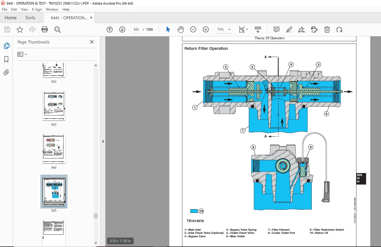
Return Filter Operation 945
Ride Control Operation 949
Diagnostic Information 954
Hydraulic System Schematic 954
Hydraulic System Component Location 956
Hydraulic System Diagnose Malfunctions 961
No Hydraulic Functions Diagnostic Procedure 961
961
961
961
962
Hydraulic Functions Slow Diagnostic Procedure 962
962
962
963
963
963
963
963
964
964
964
964
964
965
965
Hydraulic Pump Noisy Diagnostic Procedure 965
965
965
966
966
966
966
966
967
No Steering Functions Diagnostic Procedure 967
967
967
967
967
968
968
968
Boom Float Function Not Working Diagnostic Procedure 968
968
968
969
969
969
One Hydraulic Function Not Working Diagnostic Procedure 969
969
969
969
970
970
970
Hydraulic Function Drifts Down Diagnostic Procedure 970
970
970
971
971
971
971
Boom Down Does Not Work (Engine Off) Diagnostic Procedure 971
971
971
971
972
Oil Overheats Diagnostic Procedure 972
972
972
972
972
972
972
973
973
973
Hydraulic Oil Foams Diagnostic Procedure 973
973
973
974
Pin Disconnect Cylinders Will Not Retract Diagnostic Procedure 974
974
974
974
Constant Steering Required to Maintain Straight Travel Diagnostic Procedure 974
975
975
975
975
Slow Steering Wheel Movement Will Not Cause Frame Movement Diagnostic Procedure 975
975
976
Steering Wheel Turns without Resistance and Causes No Frame Movement Diagnostic Procedure 976
976
976
976
976
Steering Erratic Diagnostic Procedure 977
977
977
977
977
Steering Wheel Free Play Diagnostic Procedure 977
978
978
Steering Valve Binds or Locks Up Diagnostic Procedure 978
978
978
978
978
Steering Wheel Turns by Itself Diagnostic Procedure 979
979
979
Machine Turns in Opposite Direction as Steering Wheel Diagnostic Procedure 979
979
Steering Wheel Kickback Diagnostic Procedure 979
979
Steering Jerky Diagnostic Procedure 980
980
980
Secondary Steering Motor Will Not Operate Diagnostic Procedure 980
980
980
Secondary Steering Pump Runs but Will Not Steer Machine Diagnostic Procedure 980
980
Adjustments 981
Hydraulic Oil Clean-Up Procedure Using Portable Filter Caddy 981
Return-to-Dig Adjustment 981
Return-to-Carry and Boom Height Kickout Adjustment 981
Pump Load Sense Differential and Standby Pressure Adjustment 981
Ride Control Accumulator Hydraulic Discharge Procedure 982
Ride Control Accumulator Charge Procedure 985
Auxiliary Valve Section—Stroke Adjustment 988
Test 989
Hydraulic Oil Warmup Procedure 989
Hydraulic System Pressure and Accumulators Discharge 990
Digital Pressure and Temperature Analyzer Installation 992
Hydraulic Fan Pump Pressure Test 992
Hydraulic Fan Motor Speed Test 994
Hydraulic Fan Pump Flow Test 995
Hydraulic Fan Motor Case Drain Test 997
Pump Load Sense Differential and Standby Pressure Test 999
Maximum System Pressure Test1001
Hydraulic Pump Flow Test1003
Hydraulic Pump Case Drain Test1005
Hydraulic Power Management Test1007
Loader System Relief and Circuit Relief Valve Pressure Test1009
Loader Cylinder Drift Test1013
Boom, Bucket and Steering Cylinder Leakage Test1015
Steering Valve Leakage Test1016
Steering Valve Drift Test1018
Secondary Steering Pump Relief Valve Pressure Test1020
Secondary Steering Manifold Primary Check Valve Leakage Test1022
Secondary Steering Manifold Secondary Check Valve Leakage Test1024
Pilot Control Valve Pressure Test—Single Lever1025
Pilot Control Valve Pressure Test—Two Lever1030
Pressure Reducing Valve Pressure Test1035
Cycle Time Test1035
Brake Accumulator Precharge Test1036
Boom Down Accumulator Precharge Test1039
Brake Valve Pressure Test1041
Brake Valve Leakage Test1043
Brake Accumulator Inlet Check Valve Leakage Test1044
Pin Disconnect Pressure Test1046
Hydraulic Oil Filter Inspection Procedure1047
Heating And Air Conditioning1049
Theory Of Operation1051
Air Conditioning System Cycle Of Operation1051
Diagnostic Information1053
Air Conditioning System Diagnose Malfunctions1053
Air Conditioning System Does Not Operate Diagnostic Procedure1053
1053
1053
1054
1054
1054
1054
1054
1055
1055
1055
1055
Air Conditioner Does Not Cool Interior of Cab Diagnostic Procedure1055
1056
1056
1056
1056
1056
1057
1057
1057
1057
1057
Air Conditioner Runs Constantly, Too Cold Diagnostic Procedure1057
1058
1058
Interior Windows Continue to Fog Diagnostic Procedure1058
1058
Heater System Diagnose Malfunctions1058
Heater System Does Not Operate Diagnostic Procedure1058
1058
1059
1059
1059
Heater Does Not Warm Interior of Cab Diagnostic Procedure1060
1060
1060
1060
1060
1060
1060
Interior Windows Continue to Fog Diagnostic Procedure1061
1061
Tests1063
Air Conditioning System Fittings Reference Chart1063
Refrigerant Cautions and Proper Handling1065
R134a Refrigerant Cautions1066
Refrigerant Hoses And Tubing Inspection1067
R134a Oil Charge Capacity1067
R134a Refrigerant Charge Capacity1068
R134a Air Conditioning System Test1069
Operating Pressure Diagnostic Chart1071
Air Conditioning High/Low Pressure Switch Test1074
Freeze Control Switch Test1076
Refrigerant Leak Testing1077
DESCRIPTION:
John Deere 644J Loader Operation and Test Technical Manual SN611232 – PDF DOWNLOAD
- Foreword :
- This manual is written for an experienced technician. Essential tools required in performing certain service work are identified in this manual and are recommended for use. Live with safety: Read the safety messages in the introduction of this manual and the cautions presented throughout the text of the manual.
- This is the safety-alert symbol. When you see this symbol on the machine or in this manual, be alert to the potential for personal injury. Technical manuals are divided in two parts: repair and operation and tests. Repair sections tell how to repair the components.
- Operation and tests sections help you identify the majority of routine failures quickly. Information is organized in groups for the various components requiring service instruction. At the beginning of each group are summary listings of all applicable essential tools, service equipment and tools, other materials needed to do the job, service parts kits, specifications, wear tolerances, and torque values.
- Technical Manuals are concise guides for specific machines. They are on-the-job guides containing only the vital information needed for diagnosis, analysis, testing, and repair. Fundamental service information is available from other sources covering basic theory of operation, fundamentals of troubleshooting, general maintenance, and basic type of failures and their causes.
G.B 06/01/25