John Deere 550A Crawler Bulldozer 555A Crawler Loader PARTS MANUAL TM1292 PDF
$34.95
John Deere 550A Crawler Bulldozer 555A Crawler Loader PARTS MANUAL TM1292 – PDF DOWNLOAD
Description
John Deere 550A Crawler Bulldozer 555A Crawler Loader PARTS MANUAL TM1292 – PDF DOWNLOAD
FILE DETAILS:
John Deere 550A Crawler Bulldozer 555A Crawler Loader PARTS MANUAL TM1292 – PDF DOWNLOAD
Language : English
Pages :896
Downloadable : Yes
File Type : PDF
IMAGES PREVIEW OF THE MANUAL:
DESCRIPTION:
John Deere 550A Crawler Bulldozer 555A Crawler Loader PARTS MANUAL TM1292 – PDF DOWNLOAD
TO THE CUSTOMER
THE PART NUMBERS IN THIS PARTS CATALOG WERE CORRECT AT THE TIME THIS CATALOG WAS PUBLISHED. IT IS OUR POLICY TO CONSTANTLY IMPROVE OUR MACHINES AND, THEREFORE, PART NUMBERS MAY CHANGE. WHEN ORDERING PARTS, VERIFY PART NUMBERS THROUGH YOUR DEALER.
TABLE OF CONTENTS:
John Deere 550A Crawler Bulldozer 555A Crawler Loader PARTS MANUAL TM1292 – PDF DOWNLOAD
Contents 3
Introduction 5
General Information 13
General Specificaitons 13
Lubrication 21
Tracks 29
Track System 31
Special Tools 31
Other Materials 31
Specifications 32
Torque 32
Track 33
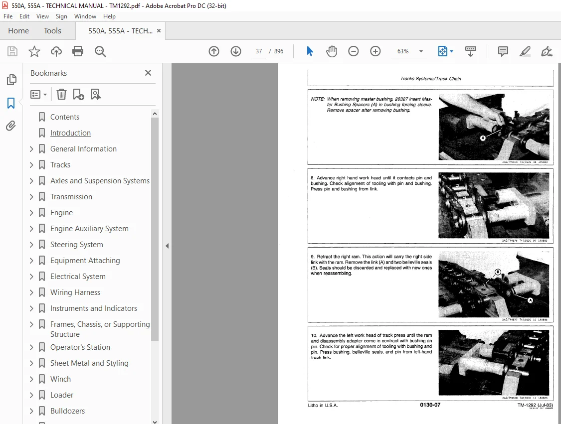
Track Chain 33
Remove 33
Disassemble 35
Assemble 39
Remove Drive Sprocket 44
Remove Track Frame 45
Upper Carrier Roller Assembly 45
Remove 45
Disassemble and Inspect 46
Assemble 47
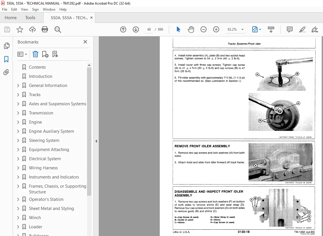
Front Idler Assembly 48
Remove 48
Disassemble and Inspect 48
Assemble 50
Hydraulic Track Tension Adjuster 51
Remove 51
Disassemble and Inspect 52
Assemble 53
Remove Track Idler Recoil Spring 53
Track Rollers 54
Remove 54
Disassemble 55
Assemble 55
Inspect and Repair Track Frame 57
Install Track Components 57
Track Rollers 57
Idler Recoil Spring 58
Hydraulic Track Tension Spring 58
Front Idler Assembly 59
Track Frame 59
Drive Sprockets 60
Upper Carrier Roller Assembly 61
Track Chain 61
Adjustments 62
Track Chain 62
Align Track 62
Front Idler Horizontal 63
Front Idler Vertical 64
Measurements 64
Link Height 64
Track Bushing Outer Diameter 65
Track Pitch 65
Grouser Bar Height 66
Sprocket Wear 66
Front Idler Wear 66
Upper Track Carrier Roller 67
Track Roller 67
Front Crossbar 68
Remove and Inspect 68
Install 68
Rear Crossbar 69
Remove and Inspect 69
Install 69
Axles and Suspension Systems 71
Axle Shaft, Bearing and Reduction Shafts 73
Final Drive 74
Remove 74
Disassemble 76
Assemble 79
Adjust Preload 82
Install 83
Steering Clutch and Brake Band 84
Remove 84
Disassemble 87
Inspect 88
Repair Brake Anchor and Band 89
Assemble 89
Install 92
Brake Lever Shaft and Bushings 93
Remove and Install 93
Steering Clutch Housing 94
Remove 94
Install 95
Steering and Brake Control Linkage 96
Repair 96
Transmission 99
Controls101
Other Materials101
Shift Control Linkage101
Remove and Install101
Gears, Shafts, Clutches, and Torque Converter103
Special Tools103
Other Materials103
Torque Converter housing104
Remove104
Disassemble110
Assemble113
Torque Converter118
Disassemble118
Assemble123
Power Shift127
Remove127
Disassembly128
Remove and Install Gears, Shafts, and Bearings133
Remove and Install Third Speed Idler Shaft134
Remove Forward Range Indler Gear135
Disassemble Clutches137
Disassemble Forward Clutch138
Dissassemble Reverse Clutch140
Remove Forward and Reverse Directional Clutch Piston142
Inspect Components143
Assemble Forward and Reverse Directional Clutches144
Assemble Forward/Reverse Clutches148
Disassemble First Range Clutch150
Disassemble Second Range Clutch151
Assemble First and Second Range Clutches152
Disassemble Third Range Clutch154
Assemble Third Range Clutch156
Disassemble Countershaft157
Assemble Countershaft158
Assemble158
Bevel Drive Housing165
Remove Components165
Remove Ring Gear and Pinion Shaft165
Remove Bevel Drive Housing Gears166
Disassemble Ring Gear Assembly and Quills167
Inspect Components168
Assemble Components169
Assemble Ring Gear Assembly and Quills169
Adjust Ring Gear Bearing Preload170
Adjust Cone Point170
Assemble Spiral Bevel Pinion172
Adjust Spiral bevel Gear and Ring Gear Backlash173
Install Gears and Shafts174
Power Shift Housing175
Install175
Converter Housing175
Install175
Transmission Hydraulics177
Special Tools177
Other Materials177
Remove Transmission Oil Pump177
Transmission Oil Pump178
Remove178
Inspect179
Assemble179
Control Valve180
Remove180
Disassemble181
Assemble182
Selector Valve182
Remove182
Disassemble183
Assemble185
Install187
Transmission Oil Filter187
Remove187
Disassemble188
Inspect189
Assemble189
Engine191
Removal and Installation195
Special Tools195
Torque Specifications195
Remove Engine195
Install Engine198
Crankshaft and Main Bearing199
Special Tools199
Other Materials199
Specifications200
Crankshaft and Main Bearing200
Measure Crankshaft End Play201
Measure Main Bearing Clearance and Main Journal Taper201
Remove Crankshaft and Main Bearings202
Measure Crankshaft Main Journal Diameter, Taper and Roundness203
Measure Main Bearing Diameter and Main Bearing Clearance203
Measure Main Thrust Journal Width203
Measure Main Thrust Bearing Width and Clearance204
Remove and Install Crankshaft Gear204
Remove Crankshaft Rear Wear Ring204
Install Main Bearings and Crankshaft205
Remove Crankshaft Rear Oil Seal and Wear Ring206
Install Crankshaft Rear Oil Seal and Wear Ring207
Crankshaft and Valve Actuating Means209
Special Tools209
Specifications210
Valve Lift and Valve Clearance210
Rocker Arm ASsembly210
Timign Gear Cover211
Camshaft211
Timing Gear Train212
Measure and Adjust Valve Clearances213
Measure Valve Lift215
Remove and Install Rocker Arm Cover215
Remove Rocker Arm Assembly, Pushrods, and Cam Followers216
Inspect Pushrods216
Disassemble and Inspect Rocker Arm Assembly217
Assemble Rocker Arm Assembly218
Measure Cam Followers218
Install Cam Followers, Pushrods, and Rocker Arm Assembly218
Remove Timing Gear Cover219
Remove and Install Crankshaft Front SealbInstall Timing Gear Cover220
Remove Camshaft221
Measure Camshaft End Play221
Measure Camshaft Thrust Plate Clearance222
Measure Camshaft Journals222
Measure Cmashaft Lobe Height222
Remove and Install Camshaft Gear223
Install Camshaft223
Remove Timing Gear Train and Cylinder Block Front Plate225
Measure Idler Gear Bushing and Shaft228
Remove and Install Idler Gear Bushings228
Remove and Install Idler Shafts229
Install Cylinder Block Front Plate and Timing Gear Cover230
Connecting Rods and Pistons233
Special Tools233
Specifications234
Measure Conencting Rod bearing Clearance and Connecting Rod Journal Taper235
Remove Pistons and Conencting Rods235
Measure Crankshaft Connecting Rod Journal Diamater, Taper and Roundness236
Measure Connecting Rod Bearing Diameter and Connecting Rod Bearing Clearance236
Measure Connecting Rod Bearing Bore237
Remove Piston Rings237
Measurements237
Remove and Install Piston Pin Bushing239
Assemble Piston and Connecting Rod240
Cylinder Block243
Special Tools243
Other Materials243
Specifications244
Cylinder Liner244
Cylinder Block245
Cylinder Liners245
Remove245
Measure247
Deglaze247
Install248
Remove, Clean, and Install Piston Cooling Orifices249
Measur Piston Block250
Oiling System251
Special Tools251
Other Materials251
Specifications252
Remove and Install Dipstick253
Oil Pressure Regulating Vlave253
Remove253
Repair254
Install254
Oil Pan and Oil Pump255
Remove255
Measure Oil Pump Parts255
Install257
Cylinder Head and Valves259
Special Tools259
Specifications260
Cylinder Head and Valves260
Cylinder Head260
Remove260
Measure and Repair261
Remove Valves261
Install Valves265
Install265
Fuel Injeciton System267
Special Tools267
Specifications267
Fuel Injection Pump267
Remove267
Install269
Bleed the System271
Lines and Nozzles271
Remove and Repair271
Install274
Engine Balancer275
Special Tools275
Specifications275
Balancer Shaft275
Balancer Shaft275
Remove and Repair275
Install277
Turbocharger279
Special Tools279
Specifications279
Turbocharger279
Turbocharger279
Remove279
Check Bearing Clearance280
Check Bearing Axial End Play280
Disassemble280
Inspect283
Assemble284
Water Pump287
Special Tools287
Water Pump287
Remove287
Disassemble and Inspect289
Assemble290
Install291
Thermostats, Housing and Water Piping293
Other Materials293
Thermostat293
Remove and Install293
Oil Cooler295
Special Tools295
Oil Cooler295
Remove295
Inspect 296
Install297
Fuel Filter299
Fuel Filter299
Remove and Install299
Fuel Transfer Pump301
Fuel Transfer Pump301
Remove and Install301
Starting Motors and Fastening303
Special Tools303
Other Materials303
Specifications304
Starting Motor304
Starting Motor305
Remove 305
Test305
Disassemble and Test308
Assemble317
Install321
Flywheel, Housing and Fastenings323
Special Tools323
Specifications323
Flywheel and Flywheel Housing323
Flywheel and Flywheel Housing323
Remove323
Converter Pilot Sleeve324
Remove and Install324
Ring Gear324
Remove and Install324
Flywheel and Flywheel Housing325
Install325
Engine Auxiliary System327
Cold Weather Starting Aids329
Starting Aid Switch329
Remove and Install329
Starting Aid Solenoid329
Remove and Install329
Starting Aid Line and Nozzle329
Remove and Install329
Engine Cooling System331
Specifications331
Radiator331
Remove331
Disassemble and Assemble332
Install333
Fan Belts333
Remove and Install333
Speed Control335
Shift Control Quadrant335
Remove and Install335
External Fuel Supply Systems337
Fuel Tank337
Remove337
Disassemble, Assemble, and Install337
Steering System339
Hydraulic System341
Specifications341
Steering Valve Spools341
Remove and Install341
Equipment Attaching343
Drawbar345
Remove and Install345
Electrical System347
Batteries, Supports and Cables349
Specifications349
Battery349
Batteries349
Precautions349
Booster Battery350
Remove and Install350
Alternator, Regulator, and Charging System Wiring351
Special Tools351
Alternator351
Remove 351
Disassemble351
Assemble356
Install361
Wiring Harness363
Starting Circuit Relay363
Remove and Install363
Battery Disconnect Switch363
Remove and Install363
Instruments and Indicators365
Instrument Panel, Instruments and Indicators365
Remove and Install365
Hour Meter365
Remove and Instal365
Frames, Chassis, or Supporting Structure367
Frame Installation369
Specifications369
Other Materials369
Side Frames370
Remove370
Inspect and Install371
Frame Bottom Guards373
Bottom Guards373
Remove and Install373
Chassis Weights375
Special Tools375
Sprocket Counterweight375
Remove and Install375
Rear Counterweight376
Remove and Install376
Bottom Counterweight376
Remove and Install376
Operator’s Station377
Operator’s Enclosure379
Special Tools379
Other Materials379
Specifications379
Roll-Over Protective Structure (ROPS)379
Remove379
Inspect380
Install380
Cab381
Remove381
Install381
Windshield Wiper Motor382
Remove and Install382
Cab Door and Latch382
Remove and Install382
Windowpane383
Remove and Install383
Seat384
Remove and Install384
Backhoe Seat385
Remove and Install385
Tank and Seat Assembly386
Remove386
Install390
Sheet Metal and Styling391
Hood or Engine Enclosure393
Hood393
Remove and Install393
Engine Side Guards393
Remove and Install393
Grille Housing393
Tilt or Remove393
Grille Housing Rub Bar (Loader)396
Replace396
Cowl and Cowl Support397
Remove397
Install399
Winch401
Controls Linkage403
Controls Linkage403
Remove and Install403
Winch Drive and Clutches405
Special Tools405
Other Materials405
Specifications406
Winch Repair407
Remove407
Remove Brake Band and Cylinder407
Disasemble and Assmeble Brake Band and Cylinder409
Disasemble Clutch Cover411
Assemble Clutch Cover413
Disassemble Winch Clutch415
Remove Clutch and Brake Drum416
Remove Winch Drum417
Disassemble Winch Drum420
Assemble Winch Drum421
Disassemble Gear Train423
Assemble Gear Train429
Install Drum435
Install Clutch and Brake Drum437
Adjust Ring Gear and Pinion Backlash438
Test Winch Gear Compartment Seals441
Assemble Winch Clutch442
Install Winch445
Adjust Free Spool445
Test Clutch Piston Seal and Swivel Fitting446
Burnish Brake Band447
Hydraulic System449
Specifications449
Control Valve449
Remove and Disassemble449
Assemble and Install450
Hydraulic Pump452
Remove and Disassemble452
Assemble and Install454
Loader457
Buckets459
Loader Bucket460
Remove460
Install460
Cutting Edges460
Repair460
Replace461
Multi-Purpose Bucket461
Remove461
Disassemble and Assemble462
Install463
Forks465
Lumber Fork or Pulpwood Loader465
Remove465
Disassemble and Assemble465
Install466
Controls Linkage467
Loader Control Linkage467
Remove467
Disassemble, Assemble, and Install468
Frames469
Loader Frame469
Remove469
Inspect471
Install472
Loader Boom472
Remove472
Inspect474
Install474
Align475
Hydraulic System477
Special Tools477
Other Materials477
Service Parts Kits477
Specifications478
Torque478
New Spring479
Loader Bucket Cylinder480
Remove480
Disassemble482
Inspect483
Assemble484
Install487
Loader Boom Cylinder487
Remove487
Install488
Hydraulic Pump489
Disassemble and Inspect489
Assemble490
Loader Control Valve491
Remove491
Disassemble491
Assemble503
Install503
Bulldozers505
Blades507
Model 6405 Dozer Blade507
Remove and Install507
Model 6410 Dozer Blade508
Remove and Install508
Model 6415 Dozer Blade509
Remove and Install509
Blade Track and Pivots510
Remove and Install510
Cutting Edges and End Bits510
Remove and Install510
Control Linkage511
Disassemble and Assemble511
Frames515
Special Tools515
Specifications515
Angling Frame (6405 Dozer)516
Remove516
Inspect516
Install516
Mounting Frame (6405 Dozer)517
Remove and Install517
C-Frame (6405 Dozer)517
Remove517
Inspect and ASsemble519
Install520
Boom and Lift (6410-6415 Dozer)521
Remove and Install521
Hydraulic System525
Special Tools525
Service Parts Kits525
Specifications526
New Spring526
Torque527
Hydraulic Return Filter527
Remove527
Disassemble, Inspect, and Assemble528
Install528
Hydraulic Reservoir528
Remove528
Install531
Hydraulic Pump534
Remove534
Disassemble and Inspect534
Assemble536
Install537
Hydraulic Pump Drive538
Remove538
Disassemble, Inspect, and Assemble538
Install538
Dozer Control Valves and Auxiliary Valve539
Remove539
Disassemble541
Assemble543
Install546
Selector Valve548
Remove, Disassemble, Assemble, and Install548
Flow Divider Valve549
Remove, Disassmeble, Assemble, and Install549
Dozer Cylinder549
Disassemble and Assemble549
Tilt Cylinder552
Remove and Install552
Backhoe 9300553
Backhoe555
Remove555
Install555
Buckets, Teeth, Shanks, and Side Cutters557
Install Bucket and Bucket links557
Remove and Install Cutting Edge558
Remove and Install Bucket Teeth Shank560
Repair Cracked Cutting Edge561
Control Linkage563
Other Materials563
Lever Mounting Frame and Linkage Assembly563
Remove563
Disassemble and Assemble565
Install566
Frames569
Special Tools569
Specifications569
Dipperstick569
Remove569
Install570
Boom571
Remove571
Install573
Swing Frame574
Remove574
Install576
Stabilizer577
Remove577
Install578
Hydraulic System581
Special Tools581
Other Materials581
Service Parts Kit582
Specifications582
Torque582
Control Valve583
Control Valve584
Remove584
Disassemble586
Valve Section587
Disassemble587
Lift Check588
Disasemble, Inspect, and Assemble588
Anti-Cavitation Valve589
Disassemble, Inspect and Assemble589
Relief Valve589
Disassemble and Assemble589
Orifice Plate590
Remove, Inspect, and Install590
Valve Section590
Assemble590
Control Valve591
Assemble591
Install591
Manifold Block593
Remove and Install593
Bucket Cylinder593
Remove593
Crowd Cylinder594
Remove594
Boom Cylinder594
Remove594
Stabilizer Cylinder595
Remove595
Boom, Crowd, Bucket, Stabilizer Cylinder596
Disassemble and Inspect596
Assemble598
Bucket Cylinder601
Install601
Crowd Cylinder602
Install602
Boom Cylinder 602
Install602
Stabilizer Cylinder603
Install603
Swing Cylinder604
Remove604
Disassemble605
Assemble608
Install611
Backhoe613
Backhoe615
Backhoe615
Remove615
Install616
Buckets, Teeth, Shanks, and Side Cutters617
Special Tools617
Other Materials617
Bucket and Bucket Links617
Remove617
Install618
Cutting Edge618
Remove and Install618
Repair620
Bucket Teeth620
Remove and Install620
Controls Linkage623
Other Materials623
Lever Mounting Frame and Linkage Assembly623
Remove623
Disassemble and Assemble624
Install625
Frames627
Special Tools627
Dipperstick627
Remove627
Install629
Tapered Pins and Bushings630
Remove630
Install631
Boom632
Remove632
Install632
Swing Frame633
Remove633
Install636
Valve Box637
Remove and Install637
Hydraulic System639
Special Tools639
Service Parts Kits639
Specifications640
Torque640
Control Valve641
Control Valve642
Remove642
Disassemble644
Valve Section645
Disassemble645
Lift Check Valve646
Disassemble, Inspect, and Assemble646
Anti-Cavitation Valve647
Disassemble, Inspect, and Assemble647
Relief Valve647
Disassemble and Assemble647
Orifice Plate648
Remove, Inspect, and Install648
Valve Section648
Remove648
Control Valve649
Assemble649
Install649
Stabilizer Cylinder650
Remove650
Stabilizer, Bucket, Boom, and Crowd Cylinders651
Disassemble651
Inspect655
Assemble655
Stabilizer Cylinder659
Install659
Bucket Cylinder659
Remove and Install659
Boom Cylinder660
Remove660
Install661
Crowd Cylinder662
Remove662
Install662
Swing Cylinders663
Remove663
Disassemble664
Inspect668
Assemble668
Install672
Arch or Boom, or Cranes673
Frames675
Log Arch675
Remove, Disassemble, Assemble, and Install675
PTO or Winch Drives677
Gears, Shafts, and Bearings679
Winch Drive Shaft679
Remove and Install679
Ground Conditioning Tool681
Blades, Teeth and Shanks683
Ripper Teeth and Shanks683
Remove and Install683
Frame685
Ripper Frame and Mast685
Remove and Install685
Rear Moutning Bracket685
Remove685
Install686
Hydraulic System687
Special Tools687
Specification687
Service Parts Kit687
Other Materials687
Ripper Cylinder688
Remove, Disassemble, Assemble, and Install688
System Testing697
General Information699
Seven Basic Steps of Diagnosis and Testing700
Operational Checkout Procedure701
Engine709
Special Tools709
Specifications710
Inspection711
Diagnose712
Tests719
Compression Pressure719
Engine Oil Pressure720
Cooling System Leakage721
Radiator Air Flow722
Fuel Transfer Pump Pressure723
Air Filter Restriction Indicator723
Engine Boost Pressure723
Adjustments725
Injection Pump Cam Advance725
Injection Pump Idle Speed and Control Linkage726
Electrical System727
General Information727
Connection List730
Block Diagram731
Schematic Diagram732
Wiring Harness Layout734
Batteries739
Battery Test741
Starting Circuit742
Diagnosing Malfunctions in Starting Circuit744
Starting Circuit Test747
Charging Circuit749
Diagnosing Malfunction In Charging Circuit751
Charging Circuit Test753
Testing Accessories758
Testing Fuel Injection Pump Solenoid758
Testing Gauges758
Testing Cigar Lighter759
Testing Starting Aid759
Testing Horn759
Testing Return-To-Dig760
Power Train761
Power Train Component Location762
Power Train Block Diagram763
Torque Converter764
Operation764
Oil Flow766
Stall Test767
Transmission768
Operation768
Power Flow769
Oil Flow773
Diagnosing Malfunctions786
Adjust Shift Lever787
Pressure Test Ports788
Powershift Transmission Test789
Steering Clutches793
Operation793
Power Flow794
Oil Flow795
Diagnosing Malfunctions795
Adjust Steering Brake Self Adjuster796
Adjust Steering Clutches and Brakes (Lever Steer)798
Adjust Steering Clutches and Brakes (Pedal Steer)799
Hydraulics801
Powertrain Hydraulics802
Test Specifications802
Component Location805
Operation806
Diagnosing Malfunctions807
Pressure Test Ports808
Install Tachometer/Temperature Reader808
Powertrain Hydraulic System Pressure Test810
Cooler Flow and Converter Inlet Relief Valve Test812
Cooler Presure Differential Test814
Cooler Inlet Pressure Test816
Transmission Pump Test818
Main Hydraulic System820
Test Specifications820
Block Diagram824
Loader Hydraulic System Operation825
Dozer Hydraulic System Operation832
Diagnosing Malfunctions840
Relief Valve Test842
Selector Valve Relief Valve Test844
Hydraulic Pump Efficiency Test846
Hydraulic Pump Flow Test847
Hydraulic Pump Flow Test (Analyzer)849
Flow Divider test852
Loader and Dozer Drift Test Per Minute854
9300 and 9550 Backhoe Boom, Crowd, and Bucket Drift Test Per Minute856
Stabilizer Cylinder Drift Test Per Minute858
Miscellaneous Components859
Track860
Diagnosing Components860
Adjust Track Chain861
Align Track Chain861
Loader862
Align Loader Boom862
Bucket Return-to-Dig Operation863
Adjust Return-to-Dig864
Lumber Forks864
Adjust Ripper Teeth 865
Adjust Operator’s Seat865
Adjust Backhoe Seat866
9550 and 9300 Backhoe866
Operation866
Neutral Oil Flow868
Boom Circuit Power Flow869
Winch870
Operation870
Oil Flow871
Diagnosing Malfunctions in Winch System875
Adjust Winch Control Lever876
Adjust Winch Brake Band877
Adjust Winch Brake Band Support Screw877
Adjust Winch Control Valve878
Winch Hydraulic Pump Test880
Special Tools883
Liner Holder Fixture885
Track Roller Installation Tool886
Final Drive Housing Lifting Tool887
Flanged Axle Shaft Removing Tool888
Clutch Housing Alignment Tool888
Starting Motor Communtator and Drive End Bushing ToolbStarting Motor Center Bushing Tool889
Turbine Wheel Holding Fixture890
Fuel Injection Pump Removal Wrench890
Fuel Injection Pump Drive Shaft Driver891
Sprocket Weight Lifting Tool891
Winch lifting Tool892
Winch Pump Removal and Installation Tool893
Swing Cylinder Removal and Installation Bar893
S.M 4/1/25