Trusted Business
Verified & Licensed
Virus Free Files
100% Safe Downloads
Secure Payment
SSL Protected
Instant Delivery
Available Immediately
John Deere 544J Loader Repair Technical Manual Serial No.611800 PDF
$29.95
John Deere 544J Loader Repair Technical Manual Serial No.611800 – PDF DOWNLOAD
Instant PDF Download
Available immediately
Save to Your Device
Download & keep forever
Antivirus Scanned
100% virus-free
Trusted Worldwide
175,000+ customers
Description
John Deere 544J Loader Repair Technical Manual Serial No.611800 – PDF DOWNLOAD
FILE DETAILS:
John Deere 544J Loader Repair Technical Manual Serial No.611800 – PDF DOWNLOAD
Language : English
Pages : 442
Downloadable : Yes
File Type : PDF
IMAGES PREVIEW OF THE MANUAL:
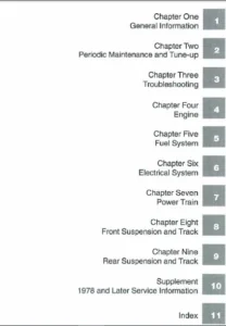
TABLE OF CONTENTS:
John Deere 544J Loader Repair Technical Manual Serial No.611800 – PDF DOWNLOAD
Contents 5
General Information 9
Safety Information 11
Recognize Safety Information 11
Follow Safety Instructions 11
Operate Only If Qualified 12
Wear Protective Equipment 12
Avoid Unauthorized Machine Modifications 12
Add Cab Guarding For Special Uses 13
Inspect Machine 13
Stay Clear of Moving Parts 13
Avoid High-Pressure Fluids 14
Avoid High-Pressure Oils 14
Beware of Exhaust Fumes 15
Prevent Fires 15
Prevent Battery Explosions 15
Handle Chemical Products Safely 16
Dispose of Waste Properly 16
Prepare for Emergencies 16
Use Steps and Handholds Correctly 17
Start Only From Operator’s Seat 17
Use and Maintain Seat Belt 17
Prevent Unintended Machine Movement 18
Avoid Work Site Hazards 19
Use Special Care When Operating Loader 20
Keep Riders Off Machine 20
Avoid Backover Accidents 21
Avoid Machine Tip Over 21
Operating on Slopes 22
Operating or Traveling On Public Roads 22
Inspect and Maintain ROPS 23
Add and Operate Attachments Safely 23
Park And Prepare For Service Safely 24
Service Cooling System Safely 24
Remove Paint Before Welding or Heating 25
Make Welding Repairs Safely 26
Drive Metal Pins Safely 26
Wheels 27
Powered Wheels and Fasteners 29
Wheel Remove and Install 29
Tire Remove 30
Tire Install 32
Axles and Suspension Systems 33
Removal and Installation 35
TeamMate™ IV Axles 35
Front Axle and Differential Remove and Install 35
Rear Axle and Differential Remove 39
Rear Axle and Differential Install 46
Axle Oscillating Supports Disassemble and Assemble 48
Axle Shafts and U-Joints 52
Universal Joint and Drive Shaft Remove and Install 52
Axle Shaft, Bearings, Reduction Gears 55
TeamMate™ IV Axles 55
Hydraulic System 57
Differential Lock Solenoid Valve Remove and Install 57
Axle Circulation System 60
Axle Oil Coolers Disassemble and Assemble 62
Transmission 63
Removal and Installation 65
Transmission Remove and Install 65
Gears, Shafts, Bearings and Power Shift Clutch 69
Torque Converter and Housing Remove 69
Torque Converter and Housing Install 72
Clutches, Input and Output Shafts Remove 76
Clutches, Input and Output Shafts Install 81
Clutch Pack KV and KR Disassemble 90
Clutch Pack KV and KR Assemble 93
Input Shaft Disassemble102
Input Shaft Assemble104
Hydraulic System107
Transmission Pump Remove and Install107
Converter Minimum Pressure Regulator Valve Remove and Install113
Transmission Control Valve Remove and Install114
Transmission Hydraulic Control Valve Cross Section View118
Transmission Control Valve Disassemble and Assemble119
Torque Converter Relief Valve Remove, Disassemble and Install134
Transmission Internal Oil Pipes and Tubes137
Remove and install137
Engine143
Removal and Installation145
PowerTech E™ (6068) John Deere Engine145
Serpentine Belt Remove and Install145
Crankshaft Dampener Remove and Install146
Engine Remove and Install148
Engine Auxiliary Systems157
Cold Weather Starting Aids159
Start Aid Nozzle Remove and Install159
Start Aid Solenoid Remove and Install160
Engine Coolant Heater Remove and Install160
Cooling System163
Intercooler Remove and Install163
Radiator Remove and Install163
Hydraulic Oil Cooler Remove and Install167
Transmission Oil Cooler Remove and Install168
Cooling Package Plenum Remove and Install170
Intake System178
Air Cleaner Remove and Install178
Element Inspect180
External Exhaust System182
Muffler Remove and Install182
External Fuel Supply Systems185
Fuel Tank Remove and Install185
Primary Fuel Filter (Water Separator) Remove and Install189
Dampener Drive191
Elements193
Output Dampener Remove and Install193
Steering System195
Hydraulic System197
Steering Valve Remove and Install197
Steering Column Remove and Install202
Steering Column Disassemble and Assemble203
Steering Cylinders Remove and Install (SN —618133)204
Steering Cylinders Remove and Install (SN 618134— )205
Steering Cylinder Bushings Remove and Install (SN —618133)208
Steering Cylinder Bushings Remove and Install (SN 618134— )209
Loader Start-Up Procedure (Steering Cylinder)210
Service Brakes211
Active Elements213
Service Brake Assembly Remove and Install213
Brake Pedal and Linkage Disassemble and Assemble214
Hydraulic System217
Brake Valve Remove and Install217
Brake Accumulator Remove and Install219
Park Brake221
Active Elements223
Park Brake Remove and Install223
Park Brake Disassemble and Assemble226
Hydraulic System231
Park Brake Release Solenoid Valve Remove and Install231
Frame or Supporting Structure233
Frame Installation235
Welding Major Structure235
Engine and Loader Frame Separate236
Upper Pivot Bearing and Seals Remove and Install240
Lower Pivot Bearing and Seals Remove and Install242
Frame Bottom Guards245
Front Axle Guard Remove and Install245
Transmission Bottom Guard Remove and Install246
Chassis Weights247
Rear Counterweight Remove and Install247
Counterweights Remove and Install248
Operator’s Station251
Removal and Installation253
Cab Remove253
Cab Install259
Operator Enclosure261
Windowpanes Remove and Install261
Cab Door Hold-Open Release Adjust261
Front and Rear Windshield Wiper Motor Remove and Install262
Heating and Air Conditioning269
Air Conditioning System Fittings Reference Chart269
R134a Refrigerant Cautions271
R134a Compressor Oil Charge Check271
R134a Compressor Oil Removal272
R134a Component Oil Charge273
Leak Testing274
Refrigerant Hoses and Tubing Inspection274
R134a Refrigerant Recovery, Recycling, and Charging Station Installation Procedure275
R134a System Recover276
R134a System Evacuate277
R134a System Charge278
Air Conditioner System Cleaning Procedures280
Air Conditioner System Purge281
Air Conditioner System Flush282
Air Conditioning Module with Heater/Evaporator Coil284
Heater/Evaporator Coil Remove and Install286
Expansion Valve Remove and Install288
Freeze Control Switch Remove and Install288
Freeze Control Switch Bench Test289
Heater Control Valve Remove and Install290
Heater Control Valve Leak Check291
Main Blower Assembly Remove and Install292
Pressurizer Motor Assembly Remove and Install293
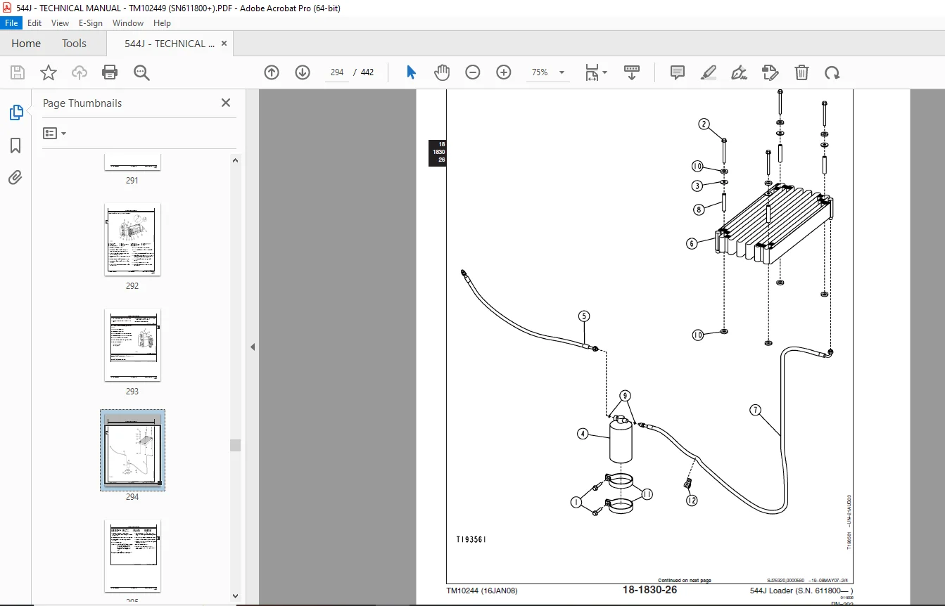
Receiver-Dryer and Condenser Remove and Install293
A/C Binary Pressure Switch Remove and Install297
Fresh Air Filter Remove and Install298
Recirculating Air Filter Remove and Install301
Compressor Remove and Install302
Compressor Clutch—R134a Disassemble and Assemble304
Clutch Hub Clearance—R134a Check305
Sheet Metal and Styling307
Hood or Engine Enclosure309
Hood Remove and Install309
Engine Side Shields Remove and Install310
Loader311
Bucket313
Bucket Remove and Install313
Powerllel™ Pin-On Bucket Remove and Install317
Welded Bucket Cutting Edges Remove and Install319
Bolt-On Cutting Edges and Wear Plates Remove and Install320
Cracked Cutting Edge Repair322
Frames323
NeverGrease™ Pin Joints323
Loader Bucket Tilt Linkage Remove and Install326
Bucket Linkage Seals and Bushings Remove and Install329
Loader Boom Bushings and Seals Remove and Install331
Boom Remove and Install333
Powerllel™ Leveling Link Disassemble and Assemble338
Powerllel™ Bellcrank Remove and Install342
Powerllel™ Bucket Cylinder Remove and Install346
Powerllel™ Bucket Link Disassemble and Assemble352
Powerllel™ Guide Links Remove and Install358
Powerllel™ Coupler Disassemble and Assemble362
Powerllel™ Loader Boom Disassemble and Assemble366
Hi-Vis Coupler Disassemble and Assemble372
Hydraulic System377
Hydraulic Oil Cleanup Procedure Using Portable Filter Caddy377
Hydraulic Pump Remove and Install378
Hydraulic Pump Disassemble and Assemble381
Loader Control Valve Remove and Install384
Loader Control Valve Disassemble and Assemble386
Auxiliary Valve Section Disassemble and Assemble388
Bucket Valve Section Disassemble and Assemble389
Boom Valve Section Disassemble and Assemble390
Inlet Valve Section Disassemble and Assemble391
Outlet Valve Section Disassemble and Assemble392
Circuit Relief Valve Disassemble and Assemble393
Bucket Circuit Relief Valve Disassemble and Assemble394
Load Sense Relief Valve Disassemble and Assemble395
Boom Anticavitation Valve Disassemble and Assemble396
Boom Cylinder Remove and Install396
Bucket Cylinder Remove and Install399
Boom and Bucket Cylinder Repair401
Boom or Bucket Cylinder Bushings and Seals Remove and Install401
Loader Start-Up Procedure402
Hydraulic Reservoir Remove and Install404
Pilot Control Valve Remove and Install408
Pilot Control Valve Disassemble and Assemble410
Boom Down Accumulator Remove and Install415
Pressure Reducing Valve Manifold Remove and Install417
Pressure Reducing Valve Manifold Disassemble and Assemble418
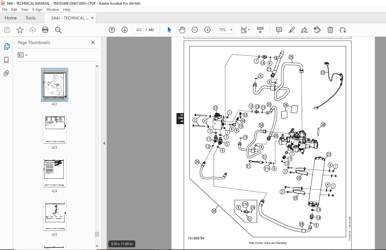
Ride Control Valve Remove and Install421
Ride Control Valve Disassemble and Assemble424
Pin Disconnect Valve Remove and Install426
Pin Disconnect Valve Disassemble and Assemble429
Fan Drive and Axle Circulation Pump Remove and Install430
Dealer Fabricated Tools433
Dealer Fabricated Tools435
DFT1132 Hydraulic Pump Removal And Installation Tool435
DFT1149 Pre-Load Clutch Pack Compression Ring Tool436
DESCRIPTION:
John Deere 544J Loader Repair Technical Manual Serial No.611800 – PDF DOWNLOAD
- Foreword:
- This manual is written for an experienced technician. Essential tools required in performing certain service work are identified in this manual and are recommended for use. Live with safety: Read the safety messages in the introduction of this manual and the cautions presented throughout the text of the manual. This is the safety-alert symbol. When you see this symbol on the machine or in this manual, be alert to the potential for personal injury.
- Technical manuals are divided in two parts: repair and operation and tests. Repair sections tell how to repair the components. Operation and tests sections help you identify the majority of routine failures quickly. Information is organized in groups for the various components requiring service instruction.
- At the beginning of each group are summary listings of all applicable essential tools, service equipment and tools, other materials needed to do the job, service parts kits, specifications, wear tolerances, and torque values. Technical Manuals are concise guides for specific machines. They are on-the-job guides containing only the vital information needed for diagnosis, analysis, testing, and repair. Fundamental service information is available from other sources covering basic theory of operation, fundamentals of troubleshooting, general maintenance, and basic type of failures and their causes.
G.B 06/01/25