John Deere 544C LOADER Technical Manual TM-1228 (Feb-84) PDF DOWNLOAD
$37.95
John Deere 544C LOADER Technical Manual TM-1228 (Feb-84) – PDF DOWNLOAD
Description
John Deere 544C LOADER Technical Manual TM-1228 (Feb-84) – PDF DOWNLOAD
FILE DETAILS:
John Deere 544C LOADER Technical Manual TM-1228 (Feb-84) – PDF DOWNLOAD
Language : English
Pages : 1389
Downloadable : Yes
File Type : PDF
IMAGES PREVIEW OF THE MANUAL:
TABLE OF CONTENTS:
John Deere 544C LOADER Technical Manual TM-1228 (Feb-84) – PDF DOWNLOAD
Contents 3
Introduction 17
General Information 23
Cap Screw Torque Values 15
Introduction And Safety Inforamtion 17
General Specifications 23
Lubrication 29
Wheels 31
Power Wheels and Fastenings 33
Special Tools 33
Loader Wheel Specifications 33
Remove Loader Wheel Assembly 33
Remove Loader Tire 34
Install Loader Tire 35
Install Loader Wheel Assembly 36
Axles And Suspension Systems 37
Removal And Installation 39
Special Tools 39
Specifications 39
Front Differential And Axle Specifications 39
Rear Differential and Axle Specifications 39
Front Axle And Differential Assembly 41
Remove 41
Install 44
Rear Axle And Differential Assembly -Put Shop Stands Under Engine Frame 47
Remove 47
Install 50
Adjust 50
Differential Or Bevel Drive 55
Special Tools 55
Specifications 55
Rear Oscillating Support 55
Bevel Pinion Shaft Rolling Drag Torque Specification 56
Bevel Pinion Shaft Nut Specification 56
Input Quill Oil Seal Specification 56
Input Quill Specification 56
Ring Gear Bushing Specifiaction 57
Right Housing Cover Specifications 57
Left Housing Cover Specifications 57
Differential Housing Preload Specification 58
Differential Housing Rolling Drag Torque Specification 58
Differential Housing Backlash Specification 58
Differential Bearing Quill 59
Differential Lock LIne Connector Specifications 59
Differential Case Specification 59
Differential Case Cover Specification 59
Front Oscillating Support 60
Remove 60
Disassemble 60
Assemble 61
Install 64
Rear Oscillating Support 65
Remove 65
Disassemble 65
Assemble 66
Install 67
Differential Cover 68
Remove 68
Disassembly 68
Assemble 103
Install 103
Differential Input Quill 69
Remove 69
Disassemble 69
Assemble 73
Adjust 74
Cone Point 74
Pinion Shaft Preload 77
Install 63
Differential Assembly 79
Remove 79
Disassemble 82
Assemble 85
Install 97
Adjust 97
Differential Preload 97
Differential Backlash 98
Test 100
Input Drive Shafts And U-Joints 105
Specifications 105
Double Universal Joint 105
Universal Joint Drive Shaft Drive Shaft 105
Support Bearing 106
Rear Differential Drive Line 106
Double Universal Joint 107
Remove 107
Disassemble And Inspect 108
Assemble 109
Install 112
Support Bearing 109
Remove 109
Install 111
Universal Joint Drive Shaft 110
Remove 110
Disassemble 110
Assemble 111
Install 111
Rear Differetial Drive Line 113
Remove 113
Disassemble 113
Assemble 114
Install 115
Axle Shaft, Bearings, Reduction Gears 117
Special Tools 117
Specifications 117
Axle Shaft 117
Axle Housing 117
Axle Housing 118
Remove 119
Disassemble 118
Assemble 127
Adjust 128
Axle Shaft 128
Install 130
Planet Pinion Carrier 120
Remove 120
Disassemble 121
Assemble 122
Hydraulic System 131
Special Tools 131
Specifications 131
Differential Lock Pressure Regulating Valve 131
Differential Lock Pressure Regulating Valve 132
Remove 132
Install 133
Differential Lock Solenoid Valve 135
Remove 135
Install 136
Transmission 137
Removal And Installation 139
Special Tools 139
Specifications 139
Transmission Mounts 139
Drive Shaft 140
Loader Pump 141
Transmission 147
Remove 147
Install 151
Controls 159
Special Tools 159
Transmission Shift Lever Assembly 159
Remove 159
Disassemble 163
Assemble 163
Install 164
Rear Axle Disconnect Linkage (644C) 168
Remove 168
Install 168
Input Drive Shaft And U-Joints 169
Specifications 169
Transmission Drive Shaft 169
Transmission Drive Shaft 169
Remove 169
Disassemble 171
Assemble 171
Install 171
Gears, Shafts, Bearing And Power Shift Clutch 173
Special Tools 173
Specifications 173
Rear Output Shaft 173
Front Output Shaft 173
Shifter Shaft 174
Reverse Range Clutch 174
Clutch Anchor 175
Low Range Clutch 175
Transfer Drive Gear 176
High Range Clutch 176
High Range Clutch Piston Housing 177
Transmission Cover Housing 177
Parking Brake and Output Flange 178
Transmission Oil Stariner 179
Transmission Oil Pump 179
Transmission Control Valve 179
Transmission 180
Disassemble 180
Assemble 205
Hydraulic System 233
Special Tools 233
Specifications 233
Transmission Oil Pump 233
Transmission Control Valve 234
Transmission Oil Cooler 235
Transmission Oil Filter 236
Transmission Oil Pump 237
Remove 237
Disassemble 238
Assemble 240
Install 241
Transmission Control Valve 243
Remove 243
Disassemble 245
Assemble 250
Install 254
Transmission Oil Cooler 257
Remove 257
Cleaning 259
Install 259
Transmission Oil FIlter Assembly 262
Remove 262
Disassemble 263
Assemble 265
Install 267
Clutch Cut-Off-Solenoid Valve 269
Remove 269
Disassemble 270
Assemble 271
Install 272
Engine 273
Removal And Installation 277
Special Tools 277
Specifications 277
Engine Installation 277
Engine 277
Remove 277
Install 284
Break-In 290
Crankshaft And Main Bearings 291
Special Tools 291
Specifications 291
Crankshaft And Main Bearing 291
Tortional Damper 293
Inspect And Replace 293
Crankshaft and Main Bearings 294
Remove 294
Inspect 296
Install 296
Crankshaft Gear 298
Remove and Install 298
Crankshaft Front Wear Ring 299
Remove and Install 299
Crankshaft Rear Wear Ring and Oil Seal 299
Remove 299
Install 301
Camshaft And Valve Actuating Means 303
Special Tools 303
Specifications 303
Camshaft 303
Rocker Arm 304
Timing Gear Train 305
Engine Front Plate 306
Valve Lift Check 306
Timing Gear Cover 307
Remove and Install 307
Crankshaft Front Oil Seal 308
Remove and Install 308
Camshaft 308
Remove 308
Install 311
Timing Gear Train 313
Remove 313
Install 315
Rocker Arms and Push Rods 319
Remove 319
Install 320
Adjust Valve Clearance 320
Connecting Rods And Pistons 323
Special Tools 323
Specifications 323
Connecting Rod And Pistons 323
Connecting Rods and Pistons 325
Remove 325
Clean Pistons 327
Inspect 328
Install 330
Cylinder Block 333
Special Tools 333
Specifications 333
Cylinder Block 333
Cylinder Block 334
Remove Liners 334
Remove Parts from Block 335
Inspect Liners 336
Install Liners 338
Oiling System 341
Specifications 341
Oiling System 341
Oil Filter 343
Remove And Install 343
Oil Pan 344
Remove And Install 344
Oil Pressure Control Valve 344
Remove 344
Disassemble 344
Repair And Assemble 345
Install 346
Oil Pump 346
Remove 346
Disassemble and Inspect 347
Assemble 348
Install 349
Dipstick Nipple 349
Remove And Install 349
Ventilating System 351
Ventilating Tube 351
Remove And Install 351
Cylinder Head And Valves 353
Special Tools 353
Specifications 353
Cylinder Head 353
Valve 354
Valve Spring 355
Cylinder Head Installation 355
Cylinder Head 356
Remove 356
Remove Valves 357
Repair 357
Assemble 360
Exhaust Manifold 363
Specifications 363
Exhaust Manifold 363
Exhaust Manifold 363
Remove and Install 363
Fuel Injection System 365
Special Tools 365
Specifications 365
Fuel Injection System 365
Fuel Injection Pump 366
Remove And Repair 366
Install 367
Bleed The Fuel System 369
Fuel Injection Nozzles 370
Remove And Repair 370
Install 372
Intake Manifold 373
Specifications 373
Intake Manifold 373
Intake Manifold 373
Remove And Install 373
Turbocharger 375
Special Tools 375
Specifications 375
Turbocharger 375
Turbocharger 376
Remove 376
Inspect and Disassemble 376
Repair 380
Assemble 381
Install 387
Water Pump 389
Special Tools 389
Specifications 389
Water Pump 389
Water Pump 390
Remove 390
Disassemble 391
Assemble 393
Install 398
Oil Cooler 399
Specifications 399
Oil Cooler 399
Oil Cooler 399
Remove 399
Repair 399
Install 401
Fuel Filter 403
Fuel Filter 403
Remove And Install 403
Fuel Transfer Pump 405
Fuel Transfer Pump 405
Remove And Install 405
Starting Motor And Fastenings 407
Special Tools 407
Specifications 407
Starting Motor 407
Starting Motor 409
Remove 409
Test 409
Disassemble 412
Test Components 418
Assemble 425
Install 430
Flywheel, Housing And Fastenings 431
Special Tools 431
Specifications 431
Flywheel 431
Damper-Drive 432
Flywheel Cover 433
Remove 433
Disassemble 433
Assemble 434
Install 435
Damper Drive 435
Remove 435
Disassemble 436
Assemble 436
Install 437
Flywheel 437
Remove 437
Repair 437
Install 438
Flywheel Housing 439
Remove 439
Install 439
Engine Auxiliary Systems 441
Cold Weather Starting Aid 443
Starting Fluid Starting Aid Solenoid 443
Remove 443
Install 443
Starting Fluid Starting Aid Nozzle 444
Remove 444
Install 445
Engine Coolant Heater 446
Remove 446
Install 446
Cooling Systems 449
Specifications 449
Thermostat 449
Radiator 449
Coolant 450
Remove from Radiator 450
Remove Engine 451
Thermostats 452
Remove 452
Test 452
Install 452
Radiator, Fan, and Fan Shroud 453
Remove 453
Repair 455
Install 455
Speed Controls 459
Speed Control Pedal 459
Remove and Install 459
Speed Control Cable 459
Remove 459
Install 459
Speed Control Bellcrank 460
Remove and Install 460
Intake System 461
Air FIlters 461
Remove 461
Install 462
Air Cleaner 463
Remove 463
Clean 464
Install 464
External Exhaust Systems 467
Muffler 467
Remove 467
Install 467
Mounting Frame 469
Specifications 469
Engine Mount 469
Engine Mount Isolator 469
Remove 469
Repair 469
Install 469
External Fuel Supply Systems 471
Fuel Tank 471
Remove 471
Repair 473
Install 473
Torque Converter 475
Turbine, Gears And Shaft 477
Special Tools 477
Specifications 477
Freewheel Clutch Assembly 477
First Turbine Driven Gear 477
Oil Suction Tube 478
Converter Pressure Regulator Valve 478
Lubrication Regulator Valve 479
Converter Housing Dowel Pin 479
Converter Ground Sleeve 479
Converter Housing To Transmission Housing 479
Input Accessory Drive Gear 480
Turbine Roll Pin 480
Converter Drive Cover Input Shaft 480
Converter Drive Cover 480
Rear Cover 481
Converter Housing Cover 481
Input Flange 481
Torque Converter 482
Remove 482
Disassemble 483
Assemble 505
Steering System 527
Emergency Steering System 529
Electrical Components 529
Remove And Install Emergency Steering Electrical Components 529
Emergency Steering Hydraulic Components 531
Remove And Install Emergency Steering Hydraulic Components 531
Hydraulic System 533
Special Tools 533
Specifications 533
Steering Valve 533
Steering Column And Metering Pump 536
Steering Return Filter 538
Accumulator 539
Feedback Cylinder 540
Steering Cylinder 541
Steering Valve 542
Remove 542
Test 543
Disassemble 546
Assemble 550
Install 557
Steering Column and Metering Pump 558
Remove 558
Disassemble 560
Steering Metering Pump 560
Steering Column 565
Assemble 562
Steering Metering Pump 562
Steering Column 567
Install 569
Steering Return Filter Assembly 571
Remove 571
Disassemble 572
Assemble 574
Install 576
Steering Accumulator 579
Remove 579
Disassemble 579
Assemble 581
Charge 583
Install 584
Steering Feedback Cylinder 585
Remove 585
Disassemble 586
Assemble 588
Install 591
Steering Cylinder 592
Remove 592
Disassemble 593
Assemble 598
Install 601
Service Brakes 603
Active Elements 605
Special Tools 605
Brakes 605
Inspect 605
Remove 606
Disaassemble 607
Assemble 608
Install 608
Controls Linkage 609
Special Tools 609
Service Brake Pedals 609
Remove 609
Disassemble 610
Assemble 612
Install 614
Hydraulic System 621
Special Tools 621
Specifications 621
Brake Valve 621
Brake Accumulator 622
Inlet Check Valve For Brake Accumulator 622
Brake Valve 623
Remove 623
Disassemble 624
Assemble 626
Install 629
Bleed Brake 630
Brake Accumulator 631
Remove 631
Disassemble 631
Assemble 633
Charge 635
Install 636
Inlet Check Valve for Brake Accumulator 637
Remove 637
Install 638
Parking-Emergency Brakes 641
Active Elements 643
Specifications 643
Parking Brake Camshaft 643
Parking Brake Elements 643
Parking Brake 644
Remove 644
Disassemble And Inspect Parking 645
Install 647
Adjust 650
Controls Linkage 653
Parking Brake Release Rod 653
Remove and Inspect 653
Install 662
Parking Brake Pedal 654
Remove And Inspect 654
Install 659
Parking Brake Cable 656
Remove And Inspect 656
Install 658
Parking Brake 663
Adjust 663
Electrical Systems 665
Batteries, Support And Cables 667
Specifications 667
Battery 667
Batteries 667
Handle Safely 667
Test 668
Remove and Install 668
Alternator, Regulator And Charging System Wiring 669
Special Tools 669
Specifications 669
Alternator 669
Alternator 672
Remove 672
Clean 672
Disassemble 673
Assemble 679
Test 682
Install 683
Lighting System 685
Specifications 685
Switch 685
Head Lights and Work Lights 685
Remove and Install 685
Tail Lights 685
Remove And Install 685
Front Turn Signal 686
Remove And Install 686
Dome Light and Switch 686
Remove And Install 686
Indicator Lights and Gauge Lights 686
Remove And Install 686
Light Switches 687
Remove And Install 687
Parking Brake Indicator Switch 687
Remove And Install 687
Brake Light Switch 687
Remove And Install 687
Flasher 687
Remove And Install 687
Wiring Harness And Switches 689
Specifications 689
Switch 689
Wire Body Connectors 689
Remove And Install 689
Horn, Start and Start Aid Switches 689
Remove and Install 689
Key Switch 690
Remove and Install 690
Windshield Wiper/Washer Switches 690
Remove and Install 690
Neutral Start and Reverse Warning Alarm Switches 690
Remove and Install 690
Blower Switch 691
Remove and Install 691
Hydraulic Filter Restriction Indicator 692
Remove and Install 692
Start Circuit Relay 692
Remove and Install 692
Air Conditioning Circuit Breaker 692
Remove and Install 692
Air Conditioning Relay 693
Remove and Install 693
Lights Circuit Breaker 693
Remove and Install 693
Fuses 693
Remove And Install 693
System Controls 695
Clutch Cut-Off Switches and Solenoid 695
Remove and Install 695
Differential Lock Switch and Solenoid 696
Remove and Install 696
Return-to-Dig and Boom Height Control Switches 696
Remove and Install 696
Instruments and Indicators 697
Gauges 697
Remove And Install Gauges 697
Air Filter Restriction Indicator 697
Remove and Install 697
Senders 698
Remove and Install 698
Hydraulic FIlter Restriction Indicator Switch 699
Remove and Install 699
Clutch Cut-Off Diode 699
Frame, Chassis Or Supporting Structure 701
Frame Installation 703
Special Tools 703
Specifications 703
Upper Pivot 703
Lower Pivot 704
Double Universal Joint 704
Steering Cylinder Pin 705
Frames 706
Inspect Pivots 706
Separate Frames 706
Repair Pivots 710
Connect Frames 716
Frame Bottom Guards 721
Engine Bottom Guards 721
Remove and Install 721
Repair 721
Auxiliary Bottom Guards (If Equipped) 722
Remove and Install 722
Chassis Weights 723
Specifications 723
Rear Weight 723
Side Weights 724
Remove and Install 724
Rear Weights 724
Remove 724
Install 726
Operator’s Station 727
Removal and Installation 729
Specifications 729
Cab(Canopy) 729
Cab 733
Remove Cab 733
Install Canopy 734
Operator Enclosure 739
Special Tools 739
Front Windhsield Wiper 739
Adjust 739
Windowpane 740
Remove 740
Install 740
Window 741
Remove and Install 741
Sliding Widnow Latch 741
Remove and Install 741
Right Front Window 742
Remove and Install 742
Cab Door 743
Remove And Install 743
Right Front Window Latch 744
Remove and Install 744
Rear Windhsield Wiper 744
Remove and Install 744
Front Windshield Wiper 745
Remove 745
Install 746
Adjust 747
WIndhsield Washer Adapter and Hose 748
Remove and Install 748
Windshield Washer Container and Pump 749
Remove and Install 749
Seat And Seat Belt 751
Specifications 751
Seat Belt 751
Seat 751
Remove 751
Disassemble 751
Assemble 757
Install 764
Adjust 765
Heating And Air Conditioning 767
Special Tools 767
Specifications 767
Compressor 767
Heater Control 769
Remove And Install Heater Control 769
Heater Valve 769
Remove And Install 769
Heater Core 771
Remove and Install 771
Discharge The System 772
Compressor 773
Remove 773
Test Compressor Efficiency 773
Test For Leaks 774
Disassemble 775
Assemble 779
Checking And Adding Compressor Oil 784
Install 785
Adjust Belt Tension 785
Condenser 786
Remove 786
Test For Leaks 786
Install 787
Receiver/Dryer 788
Remove And Install 788
Evaporator 789
Remove 789
Test For Leaks 792
Install 793
Expansion Valve 796
Remove And Install 796
Temperature Control Switch 799
Remove and Install 799
Blower Motor 801
Remove And Install Blower Motor 801
Superheat Shut-Off Switch 802
Remove And Install Superheat 802
High Pressure Relief Valve 802
Remove And Install 802
Blower Motor Resistor 803
Remove And Install 803
Sheet Metal And Styling 805
Hood Or Engine Enclosure 807
Engine Side Shield 807
Remove And Install 807
Hood 807
Remove And Install 807
Grille And Grille Housing 809
Grille Housing 811
Remove 811
Install 815
Fenders 819
Remove And Install Front Fender 819
Safety, Convenience And Miscellaneous 821
Mirror 823
Interior Mirror 823
Remove and Install 823
Rear View Mirror 823
Remove And Install 823
Horn And Warning Devices 825
Horns 825
Remove And Install 825
Horn Switch 825
Remove And Install 825
Reverse Warning Alarm 826
Remove Aand Install 826
Cigar Lighters 827
Cigar Lighter 827
Remove And Install 827
Main Hydraulic System 829
Special Tools 831
Specifications 831
Hydraulic Pump and Stroke Control Valve (Without Serial Number Plate)( -XXXXXX) 831
Hydrualic Pump and Stroke Control Valve (With Serial Number Plate) (XXXXXX- ) 835
Hydrualic Pump Drive 837
Hydrualic Pump Check Valve 837
Closed Center Module 838
O-Ring Boss Fitting Service Recommendations 839
Tube and Hose Fitting, 37 Degree Flare and 30 Degree Cone Seat Connector Service Recommendations 840
SAE Four Bolt Flange Fitting Service Recommendations 841
Hydraulic Pump and Stroke Control Valve 842
Remove 842
Disassemble and Inspect 844
Hydraulic Pump (Without Serial Number Plate 844
Hydraulic Pump (With Serial Number Plate) 861
Stroke Control Valve Assembly(pump without Serial Number Plate) 850
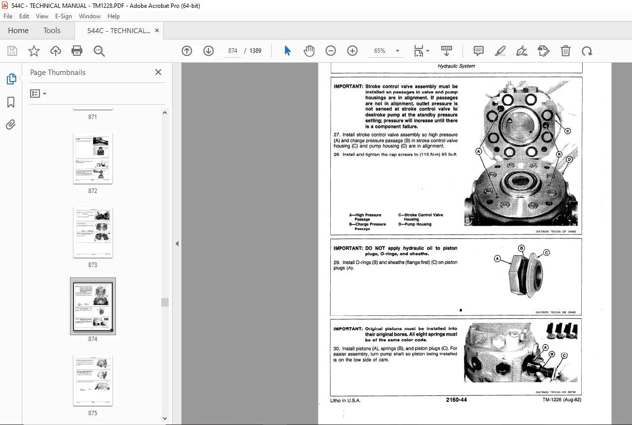
Stroke Control Valve Assembly (pump with Serial Number Plate) 875
Cross Section of Pump Housing (with Serial Number Plate) 868
Cross Section of Stroke Control Valve Assembly (pump with Serial Number Plate) 880
Assemble 852
Hydraulic Pump (without Serial Number Plate) 852
Hydraulic Pump (With Serial Number Plate) 869
Stroke Control Valve Assembly (pump without Serial Number Plate) 855
Stroke Control Valve Assembly (pump with Serial Number Plate) 881
Install 885
Hydraulic Pump Drive 886
Remove 886
Disassemble and Inspect 888
Assemble and Install 888
Hydraulic Pump Check Valve 889
Remove 889
Disassemble and Inspect 890
Assemble 891
Install 891
Closed-Center Module 892
Remove 892
Disassemble and Inspect 893
Assemble 895
Install 897
Loader 899
Buckets 901
Special Tools 901
Specifications 901
Bucket Tooth 901
Tooth Tip 902
Replace 902
Teeth 902
Remove And Install 902
Bucket 904
Remove And Install 904
Cutting Edge 907
Repair Cracks 907
Remove And Install (Multi-Purpose Bucket) 907
Remove Welded Cutting Edge 908
Install Welded Cutting Edge 909
Controls Linkage 913
Special Tools 913
Specifications 913
Loader Control Lever Assembly 914
Remove 914
Repair 916
Install 917
Frames 919
Special Tools 919
Specifications 919
Tilt Linkage 920
Remove 920
Repair 921
Install 926
Boom 922
Remove 922
Repair 924
Install 925
Hydraulic System 929
Special Tools 929
Specifications 929
Loader Hydraulic Pump 929
Loader Control Valve 930
Cylinders 933
Hydraulic Reservoir 937
Loader Hydraulic Pump 938
Remove 938
Disassemble and Inspect 939
Assemble 942
Install 946
Loader Control Valve 947
Remove 947
Disassemble 949
Assemble 974
Install 975
Boom and Bucket Cylinders 978
Remove 978
Disassemble 950
Assemble 956
Replace Bushings 988
Install 990
Multi-Purpose Bucket Cylinder 993
Remove 993
Disassemble 994
Assemble 996
Install 999
Reservoir1000
Remove1000
Disassemble1005
Assemble1007
Install1009
Backhoe1013
Removal And Installation1015
Remove 1015
Install 1018
Blades, Teeth And Shanks1021
Tooth Tip1021
Remove 1021
Install New1021
Tooth Shank1022
Remove1022
Install New 1022
Cutting Edge1022
Repair 1022
Replace (Welded Cutting Edge)1023
Buckets1025
Special Tools1025
Bucket1025
Remove 1025
Repair 1026
Install 1027
Controls Linkage1029
Control Linkage1029
Remove 1029
Disassemble 1030
Repair 1032
Assemble 1032
Install 1034
Frames1035
Special Tools1035
Tilt Linkage1035
Remove 1035
Install 1050
Dipperstick1036
Remove 1036
Repair 1045
Install 1048
Boom1037
Remove 1037
Install 1047
Swing Frame1039
Remove 1039
Repair1043
Install 1046
Stabilizer Foot1040
Remove And Install 1040
Stabilizer1040
Remove And Install 1040
Hydraulic System1052
Special Tools1052
Specifications1052
Backhoe Control Valve1052
Hydraulic Filter1054
Boom Cylinder1055
Crowd Cylinder1056
Bucket Cylinder1056
Stabilizer Cylinder1057
Swing Cylinder1057
Backhoe Cylinder Bushings1058
Backhoe Control Valve1059
Remove1059
Disassemble1060
Assemble1067
Install1083
Hydraulic Manifold Block1085
Remove1085
Install1087
Hydraulic Filter1089
Remove1089
Disassemble1090
Assemble1092
Install1094
Quick-Connect Adapters1095
Remove1095
Disassemble And Assemble1095
Install1096
Boom Cylinder1097
Remove1097
Disassemble 1099
Assemble 1103
Install 1107
Crowd Cylinder1109
Remove1109
Disassemble 1110
Assemble 1113
Install 1117
Bucket Cylinder1118
Remove 1118
Install Bucket Cylinder1129
Stabilizer Cylinder1120
Remove Stabilizer Cylinder1120
Install Stabilizer Cylinder1130
Bucket or Stabilizer Cylinder1121
Disassemble 1121
Assemble1125
Swing Cylinder1131
Remove 1131
Disassemble 1133
Assemble 1138
Install 1143
Backhoe Cylinder Bushings1145
Remove And Install1145
System Testing1146
General Information1148
Seven Basic Steps Of Diagnosis And Testing1148
Engine1150
Special Tools1150
Specifications1150
General Information1152
Design Characteristics1152
Direction Of Crankshaft Rotation1152
Cylinder Arrangement And Firing Order1152
Engine Lubrication System1153
Engine Cooling System1154
Cooling System – Cold Operation1155
Cooling System – Warm Operation1156
Fuel System1157
Air Intake System1158
Speed Control Linkage1159
Visual Inspection1160
Diagnosing Malfunction1162
Testing And Adjustment1165
Compression Pressure Test1165
Oil Pressure Test1166
Cooling System Leakage Test1167
Cooling System Pressure Cap Test1167
Fan Belt Tension Test1168
Fan Belt Tension Adjustment1168
Fuel Transfer Pump Pressure Test1169
Slow Idle Adjustment1169
Fast Idle Adjustment1170
Speed Control Linkage Adjustment1171
Air Restriction Indicator Test1172
Test Engine Performance Using Turbocharger Boost Pressure1173
Component Location Drawings1176
Electrical System1178
Special Tools1178
Electrical System Specifications1178
Precautions1179
Visual Inspection1180
Diagnosing Malfunctions1181
Testing And Adjustments1184
Starting Circuit Operation1185
Identify Starting circuit Malfunction1186
Charging Circuit Operation1191
Testing the Charging Circuit1192
Lighting Circuit1196
Gauges and Indicators Circuit1199
Air Conditioning Circuit1202
Return-To-Dig, Boom Height Kick-Out Clutch Cut-Off and Differential Lock Circuits1204
Emergency Steering Circuit1208
Miscellaneous Accessories Circuit1209
Electrical Schematic1212
Electrical Wiring Diagram1213
Component Location Drawing1216
Power Train1218
Power Flow1222
Diagnosing Malfunctions1227
Visual Inspection1228
Testing and Adjustments1229
Transmission Test1229
Parking Brake Adjustment1231
Component Location Drawing1232
Hydraulic System1234
Special Tools1235
Specifications1236
General Information1241
Closed-Center Hydraulic System1242
Hydraulic Pump and Stroke Control Valve Assembly1243
Closed-Center Module1245
Brake Valve1247
Steering System1249
Emergency Steering System1255
Transmission Filter and Steering Return Filter1257
Transmission Control Circuit1258
Open-Center Hydraulic System1266
Boom Control Valve1267
Bucket Control Valve1268
Auxiliary Control Valve1269
Loader Hydraulic Return Filter1271
Special Procedures1273
Bleed Brake Hydraulic System1273
Tachometer/Temperature Reader Installation Instructions1274
Hydraulic Oil Heat-Up Procedure1276
Flushing A Contaminated Loader Hydraulic System1277
Testing And Adjustment1279
Closed-Center Hydraulic System1280
Hydrualic Pump Standby Pressure Test1280
Hydraulic Pump Flow Test1281
Differential Lock Checkout Procedure1283
Differential Lock Pressure Test1284
Differential Lock Leakage Test1286
Brake Test1287
Steering System Checkout Pressure1289
Steering Accumulator Pressure Test1290
Steering System Control Ciruit Leakage Test1291
Steering System Pressure Circuit 1293
Emergency Steering Pressure Switch Test1295
Emergency Steering Pump Relief Valve Test1296
Transmission Checkout Procedure1298
Transmission System Pressure Test1300
Converter -Out Pressure Test1301
Transmission Lubrication Pressure Test1302
Transmission Oil Cooler Pressure Drop Test1303
Converter-Out Flow Test1304
Transmission Pump Flow Test1305
Clutch Cut-Off Valve Test1306
Backhoe Function Leakage Test1307
Open-Center Hydraulic System1309
Loader Hydraulic Pump Flow Test1311
Loader Hydraulic Pump Test (using orifice)1313
Loader Control Valve Leakage Test1314
Cylinder Leakage Test1315
Cycle Times1316
Hydraulic Schematics1318
Closed-Center Hydraulic System Schematic1318
Open-Center Hydraulic System1320
Component Location Drawings 1322
Heating And Air Conditioning1324
Special Tools1324
Specifications1325
Heating System1327
Diagnosing and Testing1327
Air Conditioning System1328
Air Conditioning Schematic1328
General Information1328
Diagnosis And Testing1330
Diagnostic Flow Chart1332
Operational Diagnostic Chart1333
Testing Superheat Shut-Off Switch1334
Testing Temperature Control Switch1334
Testing the Expansion Valve1335
Safety Precautions1336
System Service1337
Electrical Testing1337
Maniforld Gauge Set1337
Installing Manifold Gauge Set1338
Discharging the System1339
Flushing the System1339
Purging the System1340
Evacuating the System1341
Charging the System1342
Adding Refrigerant-12 to System1344
Operational Test1345
Leak Testing1346
Inspecting Refrigerant Hoses and Tubing1346
Component Location Drawing1348
DESCRIPTION:
John Deere 544C LOADER Technical Manual TM-1228 (Feb-84) – PDF DOWNLOAD
INTRODUCTION:
- This technical manual is part of a twin concept of service. FOS Manuals – for reference. Technical Manuals – for actual service. The two kinds of manuals work as a team to give you both the general background and technical details of shop service. Fundamentals of Service (FOS) Manuals cover basic theory of operation, fundamentals of troubleshooting, general maintenance, and basic types of failures and their causes. FOS Manuals are for training new personnel and for reference by experienced technicians. Technical Manuals are concise service guides for a specific machine.
- Technical manuals are on-the-job guides containing only the vital information needed by an experienced service technician. Some features of this technical manual: John Deere ILLUSTRUCTION format emphasizing more detailed pictures and a minimum use of words. Detailed repair procedures outlined in individual section. System diagnostic testing detailed in separate section.
- Table of contents of all sections at the front of the manual and a listing of all groups and headings at the front of each section. Special tools and specifications listed at the front of each group they are used in. Special tools illustrated in numerical order at end of manual. Alphabetical listing of all major components, specifications, and special tools. General specifications, lubrication requirements, and a summation of safety rules.
- This technical manual was planned and written for you – an experienced service technician. Keep it in a permanent binder in the shop where it is handy. Refer to it whenever in doubt about correct service procedures or specifications. Using the technical manual as a guide will reduce error and costly delay. It will also assure you the best in finished service work.
G.B 06/01/25