John Deere 450DLC Excavator Repair TECHNICAL MANUAL TM2362 – PDF DOWNLOAD
$33.95
John Deere 450DLC Excavator Repair TECHNICAL MANUAL TM2362 – PDF DOWNLOAD
Description
John Deere 450DLC Excavator Repair TECHNICAL MANUAL TM2362 – PDF DOWNLOAD
FILE DETAILS:
John Deere 450DLC Excavator Repair TECHNICAL MANUAL TM2362 – PDF DOWNLOAD
Language : English
Pages :648
Downloadable : Yes
File Type : PDF
IMAGES PREVIEW OF THE MANUAL:
DESCRIPTION:
John Deere 450DLC Excavator Repair TECHNICAL MANUAL TM2362 – PDF DOWNLOAD
Foreword
- This manual is written for an experienced technician. Essential tools required in performing certain service work are identified in this manual and are recommended for use. Live with safety: Read the safety messages in the introduction of this manual and the cautions presented throughout the text of the manual.
- This is the safety-alert symbol. When you see this symbol on the machine or in this manual, be alert to the potential for personal injury. Technical manuals are divided in two parts: repair and operation and tests. Repair sections tell how to repair the components. Operation and tests sections help you identify the majority of routine failures quickly. Information is organized in groups for the various components requiring service instruction.
- At the beginning of each group are summary listings of all applicable essential tools, service equipment and tools, other materials needed to do the job, service parts kits, specifications, wear tolerances, and torque values. Technical Manuals are concise guides for specific machines.
- They are on-the-job guides containing only the vital information needed for diagnosis, analysis, testing, and repair. Fundamental service information is available from other sources covering basic theory of operation, fundamentals of troubleshooting, general maintenance, and basic type of failures and their causes.
TABLE OF CONTENTS:
John Deere 450DLC Excavator Repair TECHNICAL MANUAL TM2362 – PDF DOWNLOAD
Contents 5
General Information 9
Safety 11
Recognize Safety Information 11
Follow Safety Instructions 11
Operate Only If Qualified 11
Wear Protective Equipment 12
Avoid Unauthorized Machine Modifications 12
Add Cab Guarding for Special Uses 12
Inspect Machine 13
Stay Clear of Moving Parts 13
Avoid High-Pressure Oils 13
Beware of Exhaust Fumes 14
Prevent Fires 14
Prevent Battery Explosions 14
Handle Chemical Products Safely 15
Dispose of Waste Properly 15
Prepare for Emergencies 15
Use Steps and Handholds Correctly 16
Start Only From Operator’s Seat 16
Use and Maintain Seat Belt 16
Prevent Unintended Machine Movement 17
Avoid Work Site Hazards 18
Keep Riders Off Machine 18
Avoid Backover Accidents 19
Avoid Machine Tip Over 19
Use Special Care When Lifting Objects 20
Add and Operate Attachments Safely 20
Park and Prepare for Service Safely 21
Service Cooling System Safely 21
Remove Paint Before Welding or Heating 22
Make Welding Repairs Safely 22
Drive Metal Pins Safely 23
Torque Values 25
Torque Value 25
Metric Bolt and Cap Screw 25
Additional Metric Cap Screw Torque Values 26
Torque Value 28
Unified Inch Bolt and Cap Screw 28
Service Recommendations for 37° Flare and 30° Cone Seat Connectors 29
Service Recommendations for O-Ring Boss Fittings 30
Service Recommendation 32
O-Ring Boss Fittings In Aluminum HousingExcavators 32
Service Recommendations For Flared Connections—Straight or Tapered Threads 34
Service Recommendations For Flat Face O-Ring Seal Fittings 35
Service Recommendation 37
O-Ring Face Seal Fittings with SAE Inch Hex Nut and Stud End for High Pressure 37
O-Ring Face Seal Fittings with Metric Hex Nut and Stud End for Standard Pressure 39
O-Ring Face Seal Fittings with Metric Hex Nut and Stud End for High Pressure 41
Service Recommendations for Metric Series Four Bolt Flange Fitting 43
Service Recommendations For Inch Series Four Bolt Flange Fittings 44
Service Recommendation 45
Inch Series Four Bolt Flange For High Pressure 45
Tracks 47
Track System 49
Track Roller Remove and Install 49
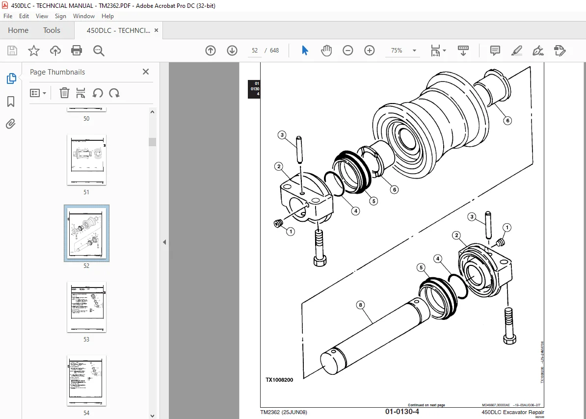
Track Roller Disassemble and Assemble 51
Track Roller Pressure Test 57
Track Carrier Roller Remove and Install 58
Track Carrier Roller Disassemble and Assemble 60
Metal Face Seal Inspection 61
Track Shoe Remove and Install 63
Track Chain Remove and Install 64
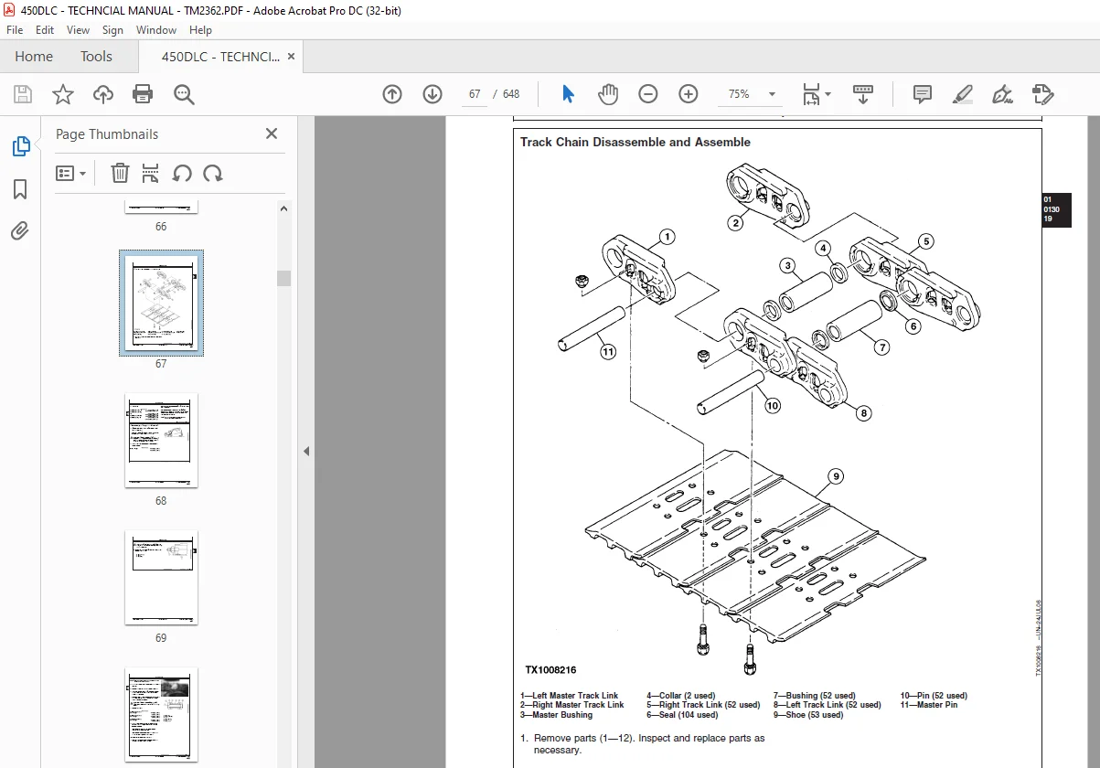
Track Chain Disassemble and Assemble 67
Track Chain Repair to Replace Broken Part 68
Sprocket Remove and Install 72
Front Idler Remove and Install 73
Front Idler Disassemble and Assemble 74
Front Idler Pressure Test 79
Track Adjuster and Recoil Spring Remove and Install 80
Track Adjuster and Recoil Spring Disassemble and Assemble 82
Track Adjuster Cylinder 86
Disassemble and Assemble 86
Axles, Differentials and Suspension Systems 89
Axle Shaft, Bearings, and Reduction Gears 91
Travel Gearbox Remove and Install 91
Travel Gearbox Disassemble and Assemble 94
Hydraulic System109
Travel Motor and Park Brake Remove and Install109
Travel Motor and Park Brake Disassemble and Assemble113
Counterbalance Valve Remove and Install118
Crossover Relief Valves Remove and Install118
Make-Up Check Valve Remove and Install119
Travel Speed Selector Valve Remove and Install119
Travel Motor and Park Brake Start-Up Procedure119
Engine121
Removal and Installation123
Engine Remove and Install123
Turbocharger Remove and Install128
Turbocharger Disassemble and Assemble130
Turbocharger Inspection138
Exhaust Manifold Remove and Install142
Upper Valve Cover Remove and Install143
Lower Valve Cover Remove and Install144
Rocker Arm Shaft Assembly Remove and Install146
Rocker Arm Shaft Assembly Disassemble and Assemble147
Rocker Arm Shaft Assembly Inspection148
Intake Manifold Remove and Install150
Lead Valve Remove and Install152
Water Pump Remove and Install153
Water Pump Disassemble and Assemble154
Cylinder Head Remove and Install157
Cylinder Head Disassemble and Assemble160
Cylinder Head Inspection169
Timing Gear Case Remove and Install175
Cylinder Block Disassemble and Assemble181
Cylinder Block Inspection183
Camshaft Remove and Install185
Camshaft Inspection186
Flywheel Remove and Install188
Flywheel Disassemble and Assemble190
Flywheel Housing Remove and Install192
Oil Pan Remove and Install194
Crankshaft Remove and Install195
Crankshaft Inspection200
Piston and Connecting Rod Remove and Install207
Piston and Connecting Rod Disassemble and Assemble210
Piston and Connecting Rod Inspection211
Engine Oil Pump Remove and Install217
Engine Oil Pump Disassemble and Assemble220
Engine Oil Pump Inspection222
Engine Oil Cooler Remove and Install224
Engine Oil Cooler Disassemble and Assemble226
Thermostat Housing Remove and Install228
Thermostat Remove and Install229
Thermostat Inspection230
Primary Exhaust Gas Recirculation (EGR) Cooler Remove and Install231
Secondary Exhaust Gas Recirculation (EGR) Cooler Remove and Install232
High Pressure Fuel Pump Remove and Install233
High Pressure Fuel Rail Remove and Install235
Fuel Injection Nozzle Remove and Install236
Starter Motor Remove and Install238
Serpentine Belt Remove and Install239
Alternator Remove and Install240
Engine Auxiliary System241
Cooling System243
Radiator Remove and Install243
Hydraulic Oil Cooler Remove and Install244
Intercooler Remove and Install246
Fuel Cooler Remove and Install248
Cooling Package Remove and Install249
Fan, Fan Guard, and Fan Shroud Remove and Install261
Coolant Recovery Tank Remove and Install262
Intake System263
Air Intake System Leakage Check263
Air Cleaner Remove and Install264
External Fuel Supply System265
Fuel Tank Remove and Install265
Primary Fuel Filter (Water Separator) Remove and Install267
Final Fuel Filter Remove and Install268
Dampener Drive (Flex Coupling)271
Elements273
Dampener Drive (Flex Coupling) Remove and Install273
Frame or Supporting Structure275
Frame Installation277
Welding On Machine277
Welding Repair of Major Structure278
Chassis Weights281
Counterweight Remove and Install281
Operator’s Station285
Removal and Installation287
Cab Remove and Install287
Operator Enclosure295
Sliding Windows Remove and Install295
Windowpanes Remove and Install296
Windowpane Dimensions297
Seat and Seat Belt315
Seat Remove and Install315
Left and Right Console Covers Remove and Install316
Seat Belt Remove and Install318
Air Suspension Seat Disassemble and Assemble320
Heating and Air Conditioning323
Refrigerant Cautions and Proper Handling323
Flush and Purge Air Conditioner System325
R134a Refrigerant Oil Information328
R134a Refrigerant Recovery/Recycling and Charging Station Installation Procedure329
Recover R134a Refrigerant330
Evacuate R134a System331
Charge R134a System332
Compressor Remove and Install332
Compressor Clutch Remove and Install334
Condenser Remove and Install336
Heater and Air Conditioner Remove and Install337
Receiver-Dryer Remove and Install340
Excavator341
Buckets343
Bucket Remove and Install343
Bucket Pin-Up Data346
Frames350
Bucket Links Remove and Install350
Arm Remove and Install352
Boom Remove and Install357
Inspect Pins, Bushings and Bosses—Front Attachment364
Bushings and Seal Remove and Install368
Hydraulic System371
Apply Vacuum to Hydraulic Oil Tank371
Hydraulic Circuit Pressure Release Procedure372
Pump 1 and 2 Remove and Install373
Pump 1 and 2 Disassemble and Assemble380
Pump 1 and 2 Inspection391
Pump 1 and 2 Start-Up Procedure392
Pump 1 and 2 Regulator Remove and Install394
Pump 1 and 2 Regulator Disassemble and Assemble396
Pilot Pump Remove and Install400
Pilot Pump Disassemble and Assemble401
Pilot Filter and Pressure Regulating Valve Remove and Install402
Pilot Filter and Pressure Regulating Valve Disassemble and Assemble404
Pilot Shutoff Solenoid Valve Remove and Install404
Pilot Shutoff Solenoid Valve Disassemble and Assemble406
Fan Drive Pump Remove and Install408
Fan Drive Pump Disassemble and Assemble412
Fan Drive Pump Regulator Remove and Install417
Fan Drive Pump Regulator Disassemble and Assemble418
Fan Drive Motor Remove and Install422
Fan Drive Motor Disassemble and Assemble444
Fan Drive Reversing Control Valve Remove and Install446
Fan Drive Reversing Control Valve Disassemble and Assemble452
Fan Drive System Relief Valve Remove and Install453
Solenoid Valve Manifold Remove and Install455
Solenoid Valve Remove and Install—Power Dig (SG), Travel Speed (SI), Boom Mode (SC) and Boom Flow Rate (SF)456
Pump Case Drain Filter and Bypass Valve Remove and Install458
Pilot Control Valve Remove and Install459
Pilot Control Valve Disassemble and Assemble464
Boom Up Shockless Valve Remove and Install471
Boom Up Shockless Valve Disassemble and Assemble474
Travel Pilot Control Valve Remove and Install475
Travel Pilot Control Valve Disassemble and Assemble478
Pilot Accumulator Remove and Install482
Pilot Check Valve Manifold Remove and Install485
Digging Sensor Manifold Remove and Install489
Travel Sensor Manifold Remove and Install491
Pilot Signal Manifold Remove and Install493
Pilot Signal Manifold Disassemble and Assemble496
Counterweight Pilot Control Valve Remove and Install499
Counterweight Pilot Control Valve Disassemble and Assemble502
Counterweight Slow Return Valve Remove and Install503
Counterweight Shutoff Valve Remove and Install505
Counterweight Check Valve Remove and Install507
Control Valve Remove and Install509
Control Valve Disassemble and Assemble513
Left Control Valve (5-Spool) Disassemble and Assemble514
Right Control Valve (4-Spool) Disassemble and Assemble526
Hydraulic Oil Tank Remove and Install536
Hydraulic Oil Tank Disassemble and Assemble538
Restriction Valve Remove and Install539
Hydraulic Oil Cooler Bypass Valve Remove and Install541
Hydraulic Oil Cooler Remove and Install543
Boom Cylinder Remove and Install545
Boom Cylinder Disassemble and Assemble550
Arm Cylinder Remove and Install553
Arm Cylinder Disassemble and Assemble559
Bucket Cylinder Remove and Install564
Bucket Cylinder Disassemble and Assemble568
Counterweight Cylinder Remove and Install573
Counterweight Cylinder Disassemble and Assemble576
Hydraulic Cylinder Bleed Procedure577
Swing or Pivoting System579
Mechanical Drive Elements581
Swing Gearbox Remove and Install581
Swing Gearbox Disassemble and Assemble584
Swing Gearbox Start-Up Procedure593
Upperstructure Remove and Install593
Swing Bearing Remove and Install595
Swing Bearing Disassemble and Assemble600
Swing Bearing Upper Seal Install603
Swing Bearing Lower Seal Install604
Hydraulic System605
Center Joint Remove and Install605
Center Joint Disassemble and Assemble608
Center joint612
Air test612
Swing Motor and Park Brake Remove and Install612
Swing Motor and Park Brake Disassemble and Assemble614
Swing Motor and Park Brake Start-Up Procedure620
Swing Motor Crossover Relief Valve Remove and Install620
Swing Motor Make-Up Check Valve Remove and Install621
Swing Park Release Valve Remove and Install624
Dealer Fabricated Tools627
Dealer Fabricated Tools629
DF1063 Lift Bracket629
DFT1250 Lifting Bracket631
DFT1130 Adapter632
DFT1109 Holding Bar633
Center Joint (Rotary Manifold) Lifting Tool634
DFT1119 Pump Support635
DFT1220 Swing Gearbox Nut Spanner Wrench638
DFRW20 Compressor Holding Fixture639
Page Numbers 5
Section 00 9
Group 01 11
S.M 6/1/25