Trusted Business
Verified & Licensed
Virus Free Files
100% Safe Downloads
Secure Payment
SSL Protected
Instant Delivery
Available Immediately
John Deere 444J,544J,624J Loader Repair Technical Manual TM2136 PDF
$29.95
John Deere 444J,544J,624J Loader Repair Technical Manual TM2136 – PDF DOWNLOAD
Instant PDF Download
Available immediately
Save to Your Device
Download & keep forever
Antivirus Scanned
100% virus-free
Trusted Worldwide
175,000+ customers
Description
John Deere 444J,544J,624J Loader Repair Technical Manual TM2136 – PDF DOWNLOAD
FILE DETAILS:
John Deere 444J,544J,624J Loader Repair Technical Manual TM2136 – PDF DOWNLOAD
Language : English
Pages : 432
Downloadable : Yes
File Type : PDF
IMAGES PREVIEW OF THE MANUAL:
TABLE OF CONTENTS:
John Deere 444J,544J,624J Loader Repair Technical Manual TM2136 – PDF DOWNLOAD
Contents 5
General Information 9
Safety Information 11
Recognize Safety Information 11
Follow Safety Instructions 11
Operate Only If Qualified 12
Wear Protective Equipment 12
Avoid Unauthorized Machine Modifications 12
Add Cab Guarding For Special Uses 13
Inspect Machine 13
Stay Clear Of Moving Parts 13
Avoid High-Pressure Fluids 14
Beware Of Exhaust Fumes 14
Prevent Fires 15
Prevent Battery Explosions 15
Handle Chemical Products Safely 16
Dispose of Waste Properly 16
Prepare for Emergencies 16
Use Steps And Handholds Correctly 17
Start Only From Operator’s Seat 17
Use And Maintain Seat Belt 17
Prevent Unintended Machine Movement 18
Avoid Work Site Hazards 18
Use Special Care When Operating Loader 19
Keep Riders Off Machine 19
Avoid Backover Accidents 20
Avoid Machine Tip Over 20
Operating on Slopes 21
Operating Or Traveling On Public Roads 21
Inspect and Maintain ROPS 22
Add And Operate Attachments Safely 22
Park And Prepare For Service Safely 23
Service Cooling System Safely 23
Remove Paint Before Welding or Heating 24
Make Welding Repairs Safely 24
Drive Metal Pins Safely 25
Wheels 27
Powered Wheels and Fasteners 29
Remove and Install Wheel 29
Remove Tire 30
Install Tire 32
Axles and Suspension Systems 33
Removal and Installation 35
TEAMMATE™ Axles 35
Front Axle and Differential Remove and Install 35
Rear Axle and Differential Remove 40
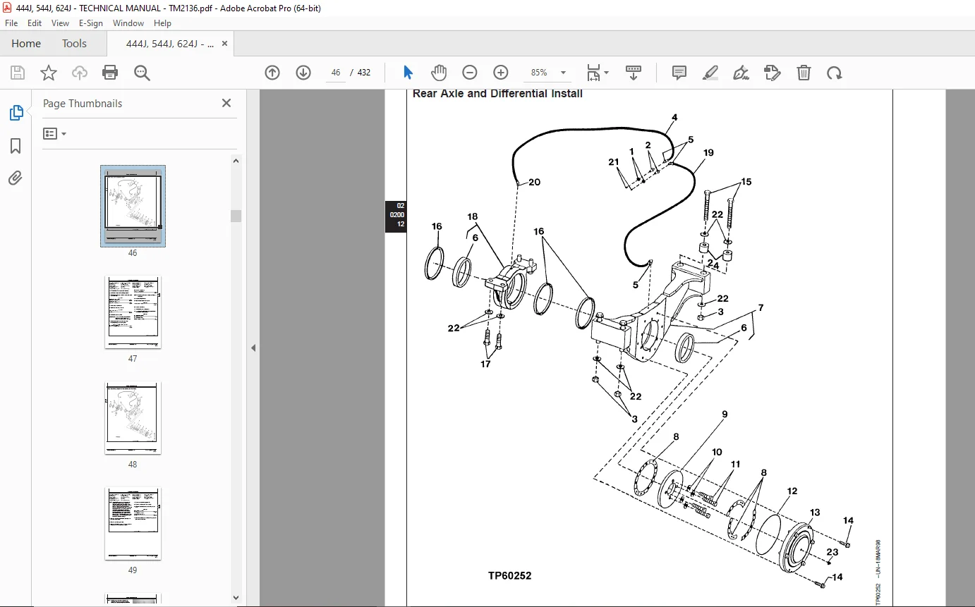
Rear Axle and Differential Install 46
Axle Oscillating Supports Disassemble and Assemble 48
Axle Shafts and U-Joints 52
Universal Joint and Drive Shaft Remove and Install 52
Axle Shaft, Bearings, Reduction Gears 55
John Deere TeamMate™ III Axles—Use CTM150 55
Axle Disconnect Input Shaft, Cross-Sectional View 56
Axle Disconnect Input Shaft Remove and Install 57
Axle Disconnect Input Shaft Disassemble, Inspect, and Assemble 57
Hydraulic System 69
Differential Lock Solenoid Valve Remove and Install 69
Axle Circulation System 70
Axle Oil Coolers 72
Axle Oil Coolers Disassemble and Assemble 73
Transmission 75
Removal and Installation 77
Transmission Remove and Install 77
Gears, Shafts, Bearings and Power Shift Clutch 81
Remove Torque Converter And Housing 81
Install Torque Converter And Housing 83
Clutches, Input and Output Shafts Remove 86
Clutches, Input and Output Shafts Install 92
Clutch Pack KV and KR Disassemble100
Clutch Pack KV and KR Assemble103
Input Shaft Disassemble112
Input Shaft Assemble112
Hydraulic System115
Remove Transmission Pump115
Remove and Install Converter Minimum Pressure Regulator Valve117
Install Transmission Pump118
Transmission Hydraulic Control Valve Remove120
Transmission Hydraulic Control Valve Install122
Transmission Hydraulic Control Valve Cross Section View126
Transmission Control Valve Disassemble128
Transmission Control Valve Assemble131
Remove, Disassemble and Install Torque Converter Relief Valve137
Oil Pipes and Tubes Replacement139
Engine141
Removal and Installation143
POWERTECH® 45 L (4045) and 68 L (6068) John Deere Engines143
Serpentine Belt Remove and Install143
Engine Remove and Install145
Engine Auxiliary Systems153
Cold Weather Starting Aids155
Starting Aid Nozzle Remove and Install155
Start Aid Solenoid Remove and Install156
Engine Coolant Heater Remove and Install156
Cooling System159
Intercooler Remove and Install159
Radiator Remove and Install160
Hydraulic Oil Cooler Remove and Install166
Transmission Oil Cooler Remove and Install167
Cooling Package Plenum Remove and Install167
Intake System175
Air Cleaner Remove and Install175
Inspect Element177
External Exhaust System179
Muffler Remove and Install179
External Fuel Supply Systems181
Fuel Tank Remove and Install181
Primary Fuel Filter (Water Separator) Remove and Install185
Dampener Drive187
Elements189
Remove and Install Dampener189
Steering System191
Hydraulic System193
Steering Valve Remove and Install193
Steering Column Remove and Install196
Steering Cylinders Remove and Install198
Loader Start-Up Procedure (Steering Cylinder)200
Service Brakes201
Active Elements203
Remove and Install Brake Assembly203
Hydraulic System205
Brake Valve Remove and Install205
Brake Accumulator Remove and Install207
Park Brake209
Active Elements211
Park Brake Remove and Install211
Park Brake Disassemble and Assemble214
Hydraulic System221
Park Brake Valve Remove and Install221
Frame or Supporting Structure225
Frame Installation227
Welding Major Structure227
Separate Engine and Loader Frame229
Upper Pivot Bearing and Seals Remove and Install232
Lower Pivot Bearing and Seals Remove and Install234
Frame Bottom Guards237
Front Axle Guard Remove and Install237
Transmission Bottom Guard Remove and Install237
Chassis Weights239
Counterweights Remove and Install239
Operator’s Station241
Removal and Installation243
Cab Remove and Install243
Operator Enclosure251
Windowpanes Remove and Install251
Cab Door Hold-Open Release Adjust251
Front and Rear Windshield Wiper Motor Remove and Install252
Heating and Air Conditioning259
Air Conditioning System Fittings Reference Chart259
R134a Refrigerant Cautions261
R134a Compressor Oil Charge Check261
R134a Compressor Oil Removal262
R134a Component Oil Charge263
Leak Testing264
Refrigerant Hoses and Tubing Inspection264
R134a Refrigerant, Recovery, Recycling and Charging Station Installation Procedure265
Recover R134a System266
Evacuate R134a System267
Charge R134a System269
Air Conditioner System Cleaning Procedures270
Purge Air Conditioner System271
Flush Air Conditioner System272
Air Conditioning Module With Heater/Evaporator Coil274
Heater/Evaporator Coil Remove and Install276
Expansion Valve Remove and Install278
Freeze Control Switch Remove and Install278
Bench Test Freeze Control Switch279
Heater Control Valve Remove and Install280
Heater Control Valve Leak Check281
Main Blower Assembly Remove and Install282
Pressurizer Motor Assembly Remove and Install283
Receiver-Dryer and Condenser Remove and Install283
A/C Binary Pressure Switch Remove and Install287
Fresh Air Filter Remove and Install288
Recirculating Air Filter Remove and Install291
Compressor Remove and Install292
Compressor Clutch—R134a Disassemble and Assemble294
Check Clutch Hub Clearance—R134a295
Sheet Metal and Styling297
Hood or Engine Enclosure299
Hood Remove and Install299
Engine Side Shields Remove and Install300
Loader303
Bucket305
Bucket Remove and Install305
Powerllel Pin-On Bucket Remove and Install307
Welded Bucket Cutting Edges Remove and Install309
Bolt-On Cutting Edges and Wear Plates Remove and Install310
Cracked Cutting Edge Repair312
Frames313
Loader Bucket Tilt Linkage Remove and Install313
Bucket Linkage Seals and Bushings Remove and Install314
Upper Tool Carrier Tilt Linkage Disassemble and Assemble316
Lower Tool Carrier Tilt Linkage Disassemble and Assemble318
Tool Carrier Disassemble and Assemble320
Loader Boom Bushings and Seals Remove and Install321
Tool Carrier Boom Bushings and Seals Remove and Install322
Powerllel Leveling Link Disassemble and Assemble324
Powerllel Bell Crank Remove and Install328
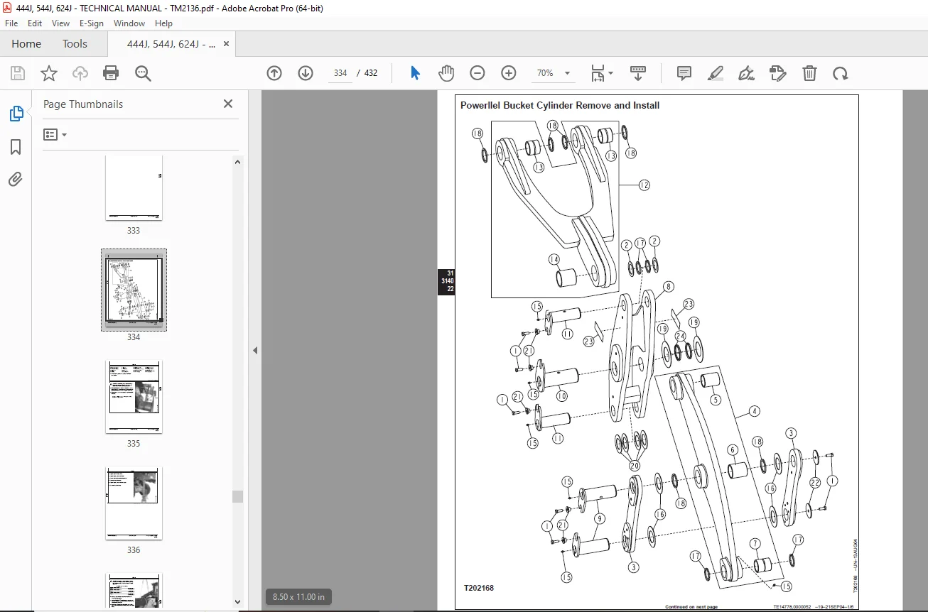
Powerllel Bucket Cylinder Remove and Install334
Powerllel Bucket Link Disassemble and Assemble340
Powerllel Guide Links Remove and Install346
Powerllel Coupler Disassemble and Assemble350
Powerllel Loader Boom Disassemble and Assemble354
Hydraulic System361
Hydraulic Pump Remove and Install361
Hydraulic Pump Disassemble and Assemble364
Loader Control Valve Remove and Install (444J, 544J SN —594432) (624J)370
Loader Control Valve Remove and Install (444J, 544J SN 594433— )374
Loader Control Valve Disassemble and Assemble (444J, 544J SN —594432) (624J)377
Loader Control Valve Disassemble and Assemble (444J, 544J SN 594433— )378
Auxiliary Valve Section and Bucket Section Disassemble and Assemble (444J, 544J SN —594432) (624J)380
Auxiliary Valve Section Disassemble and Assemble (444J, 544J SN 594433— )381
Bucket Valve Section Disassemble and Assemble (444J, 544J SN 594433— )382
Boom Valve Section Disassemble and Assemble (444J, 544J SN —594432) (624J)383
Boom Valve Section Disassemble and Assemble (444J, 544J SN 594433— )384
Inlet Valve Section Disassemble and Assemble (444J, 544J SN 594433— )385
Outlet Valve Section Disassemble and Assemble (444J, 544J SN 594433— )386
Relief Valve Disassemble and Assemble (444J, 544J SN —594432) (624J)387
Circuit Relief Valve Disassemble and Assemble387
Bucket Circuit Relief Valve Disassemble and Assemble (444J, 544J SN 594433— )388
Load Sense Relief Valve Disassemble and Assemble (444J, 544J SN —594432) (624J)389
Load Sense Relief Valve Disassemble and Assemble (444J, 544J SN 594433— )390
Boom Anti-Cavitation Valve Disassemble and Assemble391
Boom Cylinder Remove and Install391
Bucket Cylinder Remove and Install393
Boom and Bucket Cylinder Repair394
Loader Start-Up Procedure395
Hydraulic Reservoir Remove and Install397
Pilot Control Valve Remove and Install400
Pilot Control Valve Disassemble and Assemble401
Pressure Reducing Valve Manifold Remove and Install405
Pressure Reducing Valve Manifold Disassemble and Assemble407
Ride Control Valve Remove and Install408
Ride Control Valve Disassemble and Assemble412
Ride Control Accumulator Disassemble and Assemble413
Pin/Axle Disconnect Valve Remove and Install416
Pin Disconnect Valve Disassemble and Assemble417
Axle Disconnect Valve Disassemble and Assemble418
Fan Pump Remove and Install419
Dealer Fabricated Tools421
Dealer Fabricated Tools423
DFT1132 Hydraulic Pump Removal And Installation Tool423
DFT1149 Pre-Load Clutch Pack Compression Ring Tool424
DESCRIPTION:
John Deere 444J,544J,624J Loader Repair Technical Manual TM2136 – PDF DOWNLOAD
Foreword :
- This manual is written for an experienced technician. Essential tools required in performing certain service work are identified in this manual and are recommended for use.
- Live with safety: Read the safety messages in the introduction of this manual and the cautions presented throughout the text of the manual. This is the safety-alert symbol. When you see this symbol on the machine or in this manual, be alert to the potential for personal injury.
- Technical manuals are divided in two parts: repair and operation and tests. Repair sections tell how to repair the components. Operation and tests sections help you identify the majority of routine failures quickly.
- Information is organized in groups for the various components requiring service instruction. At the beginning of each group are summary listings of all applicable essential tools, service equipment and tools, other materials needed to do the job, service parts kits, specifications, wear tolerances, and torque values.
- Technical Manuals are concise guides for specific machines. They are on-the-job guides containing only the vital information needed for diagnosis, analysis, testing, and repair.
- Fundamental service information is available from other sources covering basic theory of operation, fundamentals of troubleshooting, general maintenance, and basic type of failures and their causes.
G.B 06/01/25