Trusted Business
Verified & Licensed
Virus Free Files
100% Safe Downloads
Secure Payment
SSL Protected
Instant Delivery
Available Immediately
John Deere 444J,544J,624J Loader Operation & Tests Technical Manual TM2135 PDF
$31.95
John Deere 444J,544J,624J Loader Operation & Tests Technical Manual TM2135 – PDF DOWNLOAD
Instant PDF Download
Available immediately
Save to Your Device
Download & keep forever
Antivirus Scanned
100% virus-free
Trusted Worldwide
175,000+ customers
Description
John Deere 444J,544J,624J Loader Operation & Tests Technical Manual TM2135 – PDF DOWNLOAD
FILE DETAILS:
John Deere 444J,544J,624J Loader Operation & Tests Technical Manual TM2135 – PDF DOWNLOAD
Language : English
Pages : 652
Downloadable : Yes
File Type : PDF
IMAGES PREVIEW OF THE MANUAL:
TABLE OF CONTENTS:
John Deere 444J,544J,624J Loader Operation & Tests Technical Manual TM2135 – PDF DOWNLOAD
Contents 3
General Information 5
Safety Information 7
Recognize Safety Information 7
Follow Safety Instructions 7
Operate Only If Qualified 8
Wear Protective Equipment 8
Avoid Unauthorized Machine Modifications 8
Add Cab Guarding For Special Uses 9
Inspect Machine 9
Stay Clear Of Moving Parts 9
Avoid High-Pressure Fluids 10
Beware Of Exhaust Fumes 10
Prevent Fires 11
Prevent Battery Explosions 11
Handle Chemical Products Safely 12
Dispose of Waste Properly 12
Prepare for Emergencies 12
Use Steps And Handholds Correctly 13
Start Only From Operator’s Seat 13
Use And Maintain Seat Belt 13
Prevent Unintended Machine Movement 14
Avoid Work Site Hazards 14
Use Special Care When Operating Loader 15
Keep Riders Off Machine 15
Avoid Backover Accidents 16
Avoid Machine Tip Over 16
Operating on Slopes 17
Operating Or Traveling On Public Roads 17
Inspect and Maintain ROPS 18
Add And Operate Attachments Safely 18
Park And Prepare For Service Safely 19
Service Cooling System Safely 19
Remove Paint Before Welding or Heating 20
Make Welding Repairs Safely 20
Drive Metal Pins Safely 21
Operational Checkout Procedure 23
Operational Checkout Procedure 25
Complete Machine Operational Checkout 25
Engine Off Checks 25
Engine 43
Theory of Operation 45
POWERTECH® 45 L (4045) and 68 L (6068) John Deere Engines 45
Engine Fuel System Theory of Operation 46
Engine Cooling System Theory of Operation 50
Engine Intake and Exhaust Theory of Operation 52
Engine Pilot Injection Theory of Operation—624J 53
General Engine Description 54
Diagnostic Information 55
POWERTECH® 45 L (4045) and 68 L (6068) John Deere Engines 55
Diagnose Observable Machine Symptoms—Level 11 Electronic Fuel System—624J Loader 56
Diagnose Observable Machine Symptoms—Level 12 Electronic Fuel System—444J, 544J Loader 58
Tests 61
Air Intake System Leakage Test 61
Engine Power Test Using Turbocharger Boost Pressure 62
Injection Pump Timing 64
Fuel Line Leakage Test 65
Electrical System 67
System Information 70
Electrical Diagram Information 70
System Diagrams 78
Fuse and Relay Specifications 78
System Functional Schematic, Wiring Diagram and Component Location Legend 80
System Functional Schematic and Section Legend 92
Loader Frame Harness (W2) Component Location 96
Loader Frame Harness (W2) Wiring Diagram100
Load Center Harness (W3) Component Location—444J, 544J104
Load Center Harness (W3) Wiring Diagram—444J, 544J106
Load Center Harness (W3) Component Location—624J120
Load Center Harness (W3) Wiring Diagram—624J122
Front Console Harness (W4) Component Location136
Front Console Harness (W4) Wiring Diagram138
Engine Frame Harness (W5) Component Location140
Engine Frame Harness (W5) Wiring Diagram142
Engine Harness (W6) Component Location—444J, 544J144
Engine Harness (W6) Wiring Diagram—444J, 544J148
Engine Harness With Air Heater (W6) Component Location—624J150
Engine Harness With Air Heater (W6) Wiring Diagram—624J154
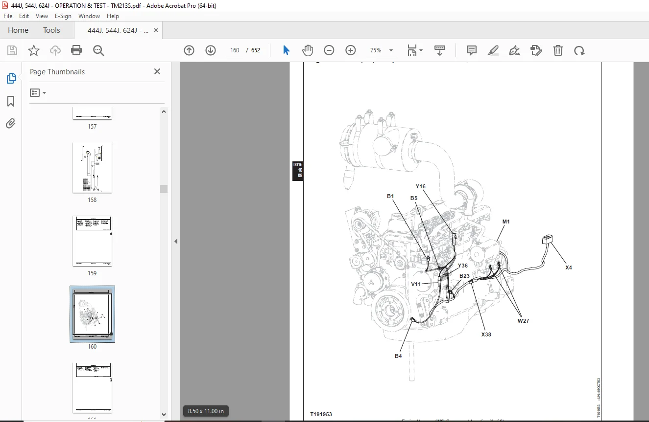
Engine Air Heater Harness (W7) Component Location—444J, 544J156
Engine Air Heater Harness (W7) Wiring Diagram—444J, 544J158
Ride Control Harness (W9) Component Location160
Ride Control Harness (W9) Wiring Diagram162
Transmission Harness (W10) Component Location164
Transmission Harness (W10) Wiring Diagram166
Rear Frame Harness (W13) Component Location168
Rear Frame Harness (W13) Wiring Diagram170
Cab Roof Harness (W19) Component Location172
Cab Roof Harness (W19) Wiring Diagram174
Blower and A/C (W20) Component Location176
Blower and A/C (W20) Wiring Diagram178
Radio Harness (W34) Component Location180
Radio Harness (W34) Wiring Diagram182
Sub-System Diagnostics185
Starting and Charging Circuit Theory of Operation185
Controller Area Network (CAN) Theory of Operation187
Engine Control Unit (ECU) Circuit Theory of Operation189
Flex Load Controller (FLC) Circuit Theory of Operation194
Transmission Control Unit (TCU) Circuit Theory of Operation207
CAN Monitor Unit (CMU) Circuit Theory of Operation210
References225
Diagnostic Trouble Codes Quick Reference List225
CAN Monitor Unit (CMU) Diagnostic Trouble Codes230
Flex Load Controller (FLC) Diagnostic Trouble Codes232
Sealed Switch Module (SSM) Diagnostic Trouble Codes244
Transmission Control Unit (TCU) Diagnostic Trouble Codes248
Engine Control Unit (ECU) Diagnostic Trouble Codes—444J, 544J259
Engine Control Unit (ECU) Diagnostic Trouble Codes—624J264
Flex Load Controller (FLC) Fault Exceptions272
Check Battery Electrolyte Level and Terminals275
Procedure For Testing Batteries277
Electrical Component Specifications279
Transmission Control Valve Solenoid Check284
Clutch Cut-Off Sensor Check and Adjustment285
Boom Height Kickout/Return-to-Carry Adjustment286
Return-to-Dig Adjustment287
Sensor Circuitry Check289
Diagnostic Trouble Codes—After Machine Repair292
Change Back-Up Alarm Volume292
Remove and Install Pressure Switches293
Replace (Push Type) Metri-Pack™ Connectors294
Replace METRI-PACK™ Connectors294
Install METRI-PACK™ Contact295
Replace DEUTSCH™ Connectors296
Install DEUTSCH™ Contact298
Replace WEATHER PACK™ Connector299
Install WEATHER PACK™ Contact300
Replace CINCH™ Connectors301
Install CINCH™ Contact303
Repair 32 and 48 Way CINCH™ Connectors304
Engine Control Unit (ECU) Remove and Install307
Flex Load Controller (FLC) Remove and Install309
Transmission Control Unit (TCU) Remove and Install310
Sealed Switch Module (SSM) Remove and Install311
CAN Monitor Unit (CMU) Remove and Install312
Reprogram CAN Monitor Unit (CMU)312
Power Train315
Theory of Operation317
TEAMMATE™ Axles317
Transmission Clutch Engagement And Solenoids Activated317
Power Train Components318
Transmission Operation320
Transmission Operation—First Gear Forward322
Transmission Filter Bypass Valve325
Transmission Control Valve Components326
Transmission Clutch Modulation329
Thermal Bypass Valve Operation330
Differential Lock Operation332
Axle Disconnect Operation334
Axle Circulation Motor and Dual Pump Operation336
Park Brake Operation337
Diagnostic Information342
Transmission Control Circuit—First Forward342
Transmission Control System344
Power Train Component Location346
Diagnose Transmission System Malfunctions352
Diagnose Differential And Axle Malfunctions367
Diagnose Service Brake Malfunctions374
Diagnose Drive Line Malfunctions376
Diagnose Park Brake Malfunctions377
Adjustments381
External Service Brake Inspection381
Transmission Control Unit (TCU)—Electronic Clutch Calibration383
Tests385
Transmission Oil Warm-Up Procedure385
Park Brake Pressure Test385
Park Brake Drag Test387
Transmission Pump Flow Test389
Transmission System Pressure Test391
Transmission Clutch Pressure Test394
Transmission Element Leakage Test397
Lube Pressure Test399
Torque Converter Stall Speed Test402
Differential Lock Pressure Test403
Converter—In Pressure Test405
Converter—Out Pressure Test407
Converter Relief Pressure Test409
Converter—Out Flow Test411
Transmission Oil Cooler Thermal Bypass Valve Temperature Test414
Transmission Oil Cooler Thermal Bypass Valve Pressure Test416
Transmission Oil Cooler Restriction Test418
Axle Circulation Dual Pump Flow and Temperature Tests420
Axle Circulation Motor Flow Test422
Axle Breather Test424
Axle Circulation Pump Inlet Suction Check425
Hydraulic System427
Theory of Operation429
Loader Hydraulic System429
Hydraulic Pump Operation430
Hydraulic Fan Drive Operation432
Steering System Components434
Steering Valve Operation435
Secondary Steering System Operation436
Secondary Steering Inlet Manifold Operation437
Pressure Reducing Valve Operation439
Service Brake Hydraulic System440
Service Brake Accumulator441
Brake442
Valve442
Pin and Axle Disconnect Operation444
Pilot Control Lever Operation446
Pilot Orifice Check Valve For Control Valve Sections448
Loader Control Valve (444J, 544J SN —594432) (624J)450
Boom Section—Boom Down And Steering (444J, 544J SN —594432) (624J)452
Boom Section—Boom Raise And Bucket Dump (444J, 544J SN —594432) (624J)454
Bucket Section—Boom Raise and Bucket Dump (444J, 544J SN —594432) (624J)456
Bucket Section—Boom Raise and Bucket Dump (High Lift Option Only) (444J, 544J SN —594432) (624J)458
Auxiliary Section—Operating And Boom Raise (444J, 544J SN —594432) (624J)460
Bucket Section Operation—Tool Carrier (444J, 544J SN —594432) (624J)462
Outlet Section Operation (444J, 544J SN —594432) (624J)464
Load Sense Circuit Operation—Neutral (444J, 544J SN —594432) (624J)466
Load Sense Circuit—Steering (444J, 544J SN —594432) (624J)468
Load Sense Circuit—Steering and Boom Down (444J, 544J SN —594432) (624J)470
Load Sense Circuit—Boom Raise and Bucket Dump (444J, 544J SN —594432) (624J)472
Relief Valve Operation (444J, 544J SN —594432) (624J)473
Load Sense Relief Valve Operation (444J, 544J SN —594432) (624J)474
Loader Control Valve (444J, 544J SN 594433— )475
Boom Section—Boom Down And Steering (444J, 544J SN 594433— )476
Boom Section—Boom Raise And Bucket Dump (444J, 544J SN 594433— )478
Bucket Section—Boom Raise and Bucket Dump (444J, 544J SN 594433— )480
Bucket Section—Boom Raise and Bucket Dump (444J High Lift Option Only) (444J, 544J SN 594433— )481
Auxiliary Sections—Stroke Adjusters483
Outlet Section Operation (444J, 544J SN 594433— )484
Load Sense Circuit Operation—Neutral (444J, 544J SN 594433— )486
Load Sense Circuit—Steering (444J, 544J SN 594433— )487
Load Sense Circuit—Steering and Boom Down (444J, 544J SN 594433— )488
Load Sense Circuit—Boom Raise and Bucket Dump (444J, 544J SN 594433— )489
Relief Valve Operation (444J, 544J SN 594433— )490
Load Sense Relief Valve Operation (444J, 544J SN 594433— )492
Circuit Relief Valve Operation493
Anti-Cavitation Valve Operation499
Return Filter Operation500
Ride Control Operation504
Diagnostic Information510
Hydraulic System Schematic (444J, 544J SN —594432) (624J)510
Hydraulic System Schematic (444J, 544J SN 594433— )512
Hydraulic System Component Location514
Diagnose Hydraulic System Malfunctions523
Adjustments535
Hydraulic Oil Clean-Up Procedure Using Portable Filter Caddy535
Return-To-Dig Adjustment536
Return-To-Carry and Boom Height Kickout Adjustment536
Pump Load Sense Differential and Standby Pressure Adjustment536
Pilot Controller Adjustment—Two Lever Pilot536
Ride Control Accumulator Hydraulic Discharge537
Charge Ride Control Accumulator538
Adjustments541
Auxiliary Valve Section—Stroke Adjustment (If Equipped)541
Test543
Hydraulic Oil Warm-Up Procedure543
Digital Pressure and Temperature Analyzer Installation543
Pump Load Sense Differential and Standby Pressure Test544
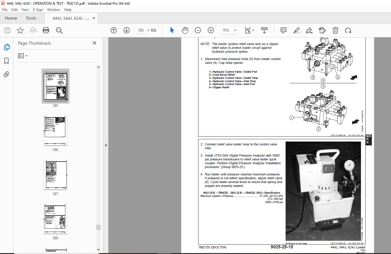
Maximum System Pressure Test547
Hydraulic Pump Flow Test551
Hydraulic Pump Case Drain Test554
Loader System Relief and Circuit Relief Valve Pressure Test (444J, 544J SN —594432) (624J)556
Loader System Relief and Circuit Relief Valve Pressure Test (444J, 544J SN 594433— )559
Loader Cylinder Drift Test563
Boom, Bucket and Steering Cylinder Leakage Test565
Steering Valve Leakage Test567
Steering Valve Drift Test570
Secondary Steering Pump Relief Valve Pressure Test572
Secondary Steering Manifold Primary Check Valve Leakage Test574
Secondary Steering Manifold Secondary Check Valve Leakage Test576
Pressure Reducing Valve Pressure Test577
Cycle Time Test578
Brake Accumulator Precharge Test579
Boom Down Accumulator Precharge Test581
Brake Valve Pressure Test582
Brake Valve Leakage Test583
Brake Accumulator Inlet Check Valve Leakage Test584
Axle And Pin Disconnect Pressure Test586
Fan Pump Pressure Test587
Fan Motor RPM Test589
Fan Pump Flow Test590
Fan Motor Case Drain Test592
Hydraulic Oil Filter Inspection Procedure594
Heating And A/C595
Theory Of Operation597
Air Conditioning System Cycle Of Operation597
Diagnostic Information599
Diagnose Air Conditioning System Malfunctions599
Diagnose Heater System Malfunctions602
Tests603
Air Conditioning System Fittings Reference Chart603
Proper Refrigerant Handling605
R134a Refrigerant Cautions605
R134a Oil Charge Capacity606
R134a Refrigerant Charge Capacity606
Refrigerant Hoses And Tubing Inspection606
R134a Air Conditioning System Test607
Operating Pressure Diagnostic Chart610
A/C Binary Pressure Switch Test613
Freeze Control Switch615
Leak Testing616
DESCRIPTION:
John Deere 444J,544J,624J Loader Operation & Tests Technical Manual TM2135 – PDF DOWNLOAD
Foreword:
- This manual is written for an experienced technician. Essential tools required in performing certain service work are identified in this manual and are recommended for use. Live with safety: Read the safety messages in the introduction of this manual and the cautions presented throughout the text of the manual.
- This is the safety-alert symbol. When you see this symbol on the machine or in this manual, be alert to the potential for personal injury. Technical manuals are divided in two parts: repair and operation and tests. Repair sections tell how to repair the components. Operation and tests sections help you identify the majority of routine failures quickly.
- Information is organized in groups for the various components requiring service instruction. At the beginning of each group are summary listings of all applicable essential tools, service equipment and tools, other materials needed to do the job, service parts kits, specifications, wear tolerances, and torque values.
- Technical Manuals are concise guides for specific machines. They are on-the-job guides containing only the vital information needed for diagnosis, analysis, testing, and repair. Fundamental service information is available from other sources covering basic theory of operation, fundamentals of troubleshooting, general maintenance, and basic type of failures and their causes.
G.B 06/01/25